Week 3 - External flow simulation over an Ahmed body.
Kindly find the PDF for the better View
Aim:
· explain the Ahmed body and its importance.
· Explain the reason for the negative pressure in the wake region.
· Explain the significance of the point of separation.
· Plot the Velocity and pressure contours.
· Plot the drag and lift coefficient for every refined case.
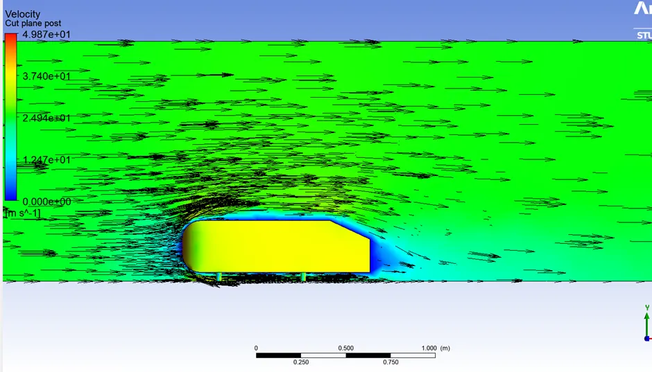
· Vector plot clearly showing the wake region.
· Perform the grid independency test and provide the values of drag and lift with each case.
Introduction:
Ahmed Body And Its Importance
The Ahmed body represents a simplified, ground vehicle geometry of a bluff body type. Its shape is simple enough to allow for accurate flow simulation but retains some important practical features relevant to automobile bodies. This model describes how to calculate the turbulent flow field around a simple car-like geometry using the Turbulent Flow, k-epsilon interface.
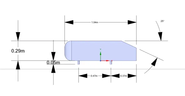
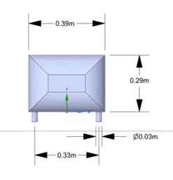
The simple geometrical shape has a length of 1.044 meters, height of 0.288 meters, and a width of 0.389 meters. It also has 0.5-meter cylindrical legs attached to the bottom of the body and the rear surface has a slant that falls off at 30 degrees.
The wake was shown to be highly dependent on slant angle. For slant angles less than 12°, the flow remains attached over the slant. The flow is essentially two-dimensional and has low drag. Between 12° and 30° the flow becomes much more three-dimensional as the c-pillar vortices form. These reach maximum strength at 30°. The drag increases significantly as the low-pressure cores act on the rear surfaces. Past 30° the flow separates fully off the slant. This results in a sudden decrease in drag and weaker c-pillar vortices.
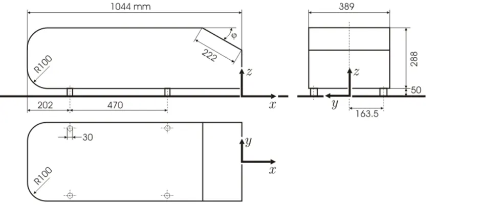
The Ahmed body is a benchmark model widely used in the automotive industry for validating simulation tools. The Ahmed Body was first created by S.R. Ahmed in his research “Some Salient Features of the Time-Averaged Ground Vehicle Wake” in 1984. Ahmed body is the benchmark model for aerodynamics simulation tools. Three main features were seen in the wake:
1. The A recirculation region that is formed as the flow separates at the top of the vertical back surface of the model
2. The B recirculation region that is formed due to the separation at the base of the model.
3. The c-pillar vortices that form as the vorticity in the side boundary layers roll up over the slant edges.
The Ahmed body is a benchmark model widely used in the automotive industry for validating simulation tools. The airflow around the Ahmed body is important because it helps to understand the fundamental physics defining the lift and drag forces and coefficients at certain characteristic velocities, pressure differences, and seeing and analyzing the vortices, turbulence, and Reynolds number obtained.
The drag coefficient quantifies the resistance of an object in a fluid environment. It is not an absolute constant for a body’s shape because it varies with the speed and direction of flow, object shape and size, and the density and viscosity of the fluid. The lower the drag coefficient of an object, the less aerodynamic or hydrodynamic drag occurs. In terms of a car, the lower the drag coefficient, the more efficient the car is. As well as affecting the top speed of a vehicle, the drag coefficient also affects the handling. Cars with a low drag coefficient are sought after, but decreasing the drag drastically can reduce the downforce and lead to loss in road traction and a higher chance of car accidents.
The reason for the negative pressure in the wake region.
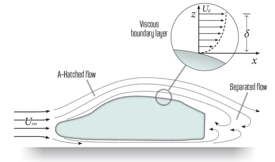
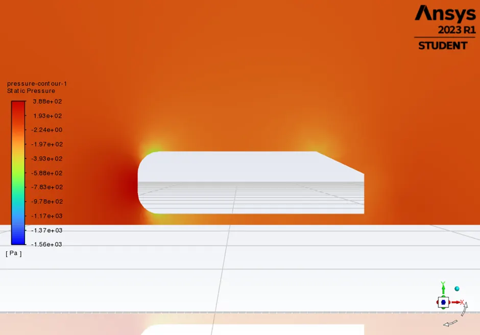
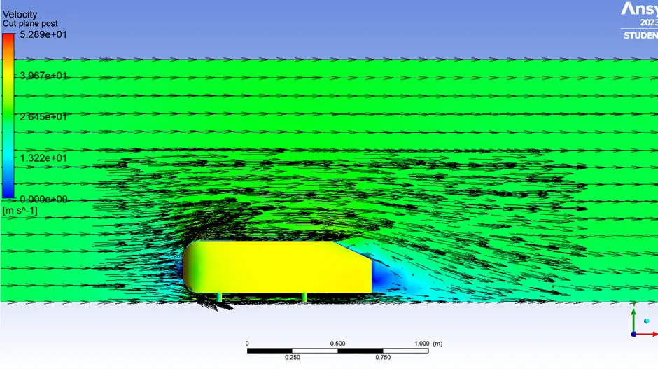
When the air moving over the vehicle is separated at the rear end, it leaves a large low pressure turbulent region behind the vehicle known as the wake. This wake contributes to the formation of pressure drag, which is eventually reduces the vehicle performance.
The rear part of the vehicle has a significant role in manipulating the drag forces. The Ahmed body is shown in figure 1. It has been observed that the slant angle (∅) greatly affects the drag results. This is majorly due to flow of separation. Separation of flow means that the flow instead of being attached or parallel to the surface gets detached from the surface and generates turbulence (by pressure gradient) which creates turbulent friction and hence creates drag force.
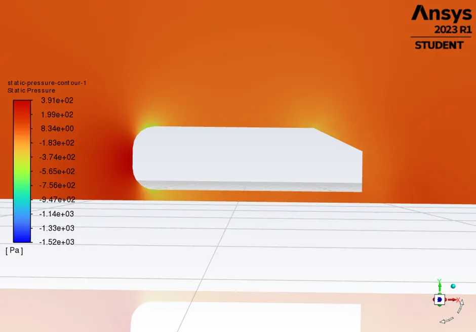
The air becomes almost stagnant as it strikes Ahmed body which results in air exerting very high pressure on the front face of Ahmed body. The airflow then gets divided between the upper and lower surface of the Ahmed body. The higher-pressure air on the front surface accelerates as it travels over the curved nose surface of Ahmed body, causing the pressure to drop. This lower pressure creates lifts over the roof surface as the air passes over it. As the air continues to flow and make its way to the rear, a notch is created by the rear slant owing to flow separation, leaving a vacuum or low-pressure space which the air is not able to fill properly. The resulting lower pressure creates lift and the drag that then acts upon the surface area of the rear slant.
The significance of the point of separation
The point of separation is the point where the air stops "sticking" to an object that is moving through the air. It is also a point, line, or means of division. The point of separation marks the detachment of the boundary layer or flow from the body surface, which often results in a turbulent flow and vortices. The point of separation affects the pressure drag on the object.
Physics /Mesh Setup
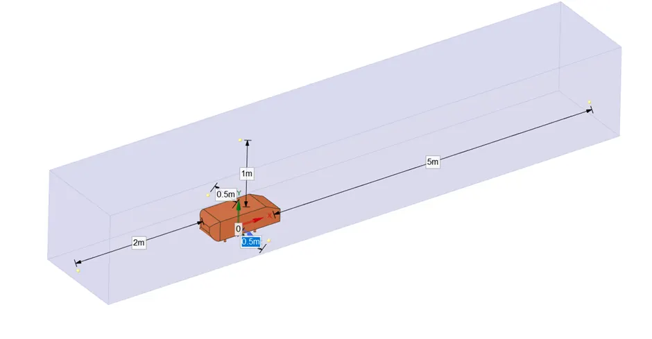
· Ahmed body loaded into space claim. Created first Enclosure with dimension as shown in the picture.
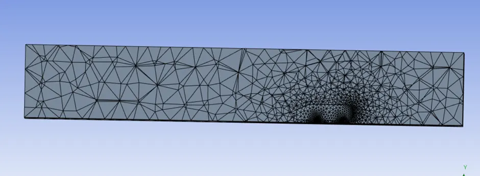
· Suppress the Ahmed body for physics. Run the base line mesh with default element size.
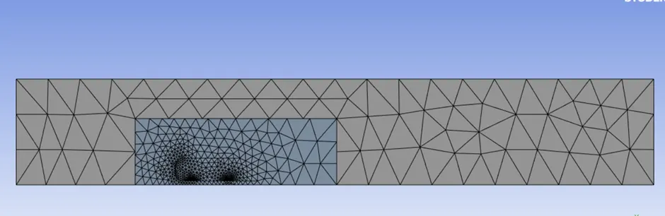
We are interested in study on Ahmed body and its drag force calculation So we need to create another enclosure, refine the mesh of that enclosure and Ahmed body according to Y+ value. We need to add the method, body sizing and inflation layer to the Ahmed body. Ahmed body is symmetrical so we will split the whole model.
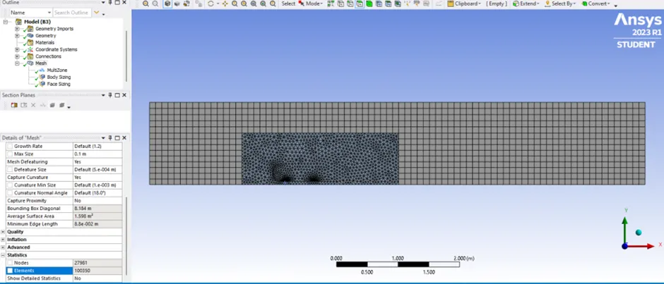
We are using multizone Hexahedral mesh is used for outer enclosure. Elment size will be 0.1m and maximum size also 0.1 m. we are using the sizing option and selected the inner enclosure. Element size will be 0.05m. Elment size for the piller of ahmed body will be 0.005m. Total number of elements 100350.
We are adding the infaltion layer to the boundary surface of ahmed body. Total layer thickness is 0.0496496m. Inflation layer 5. Growth rate will be 1.2
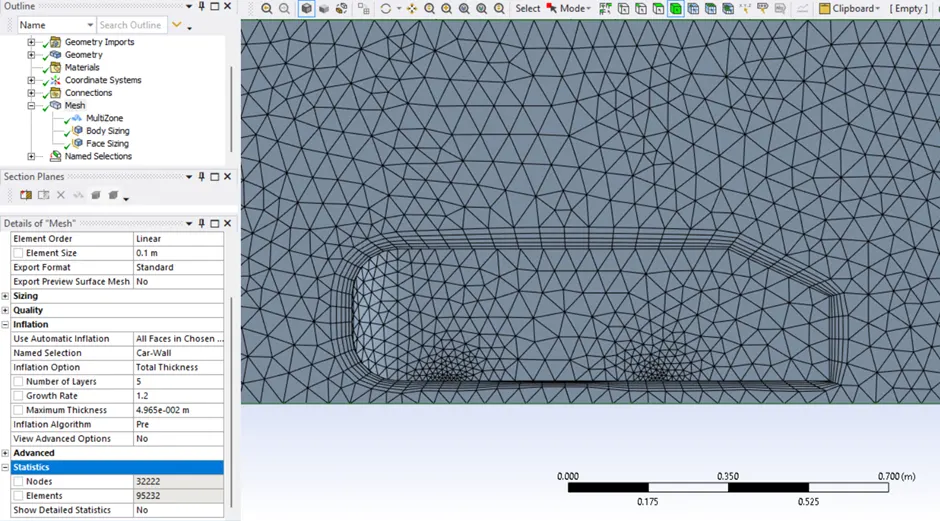
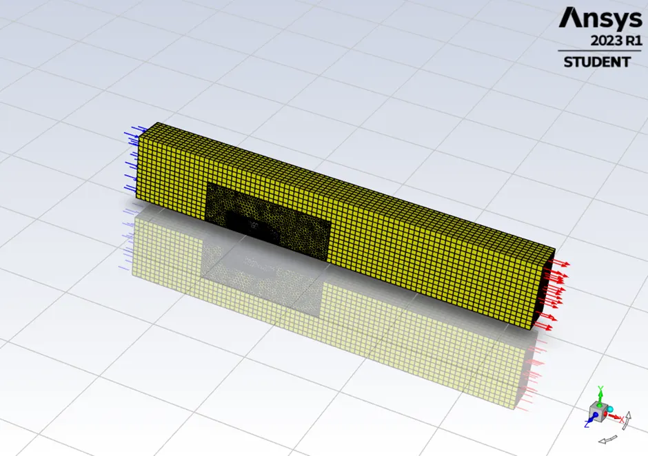
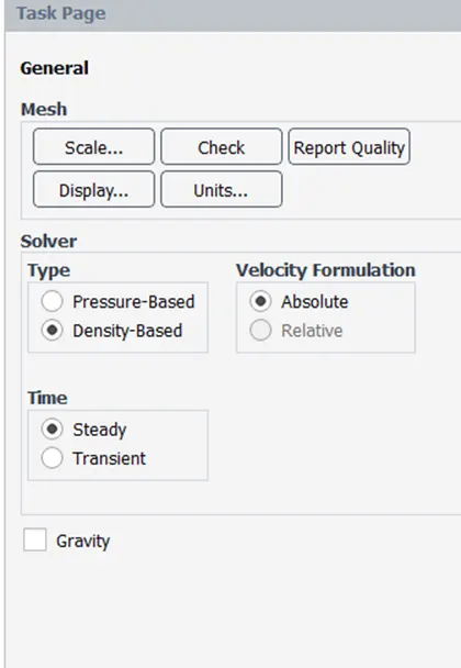
Setting up of Physics,
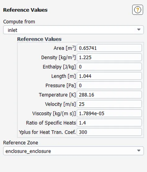
Refference Values
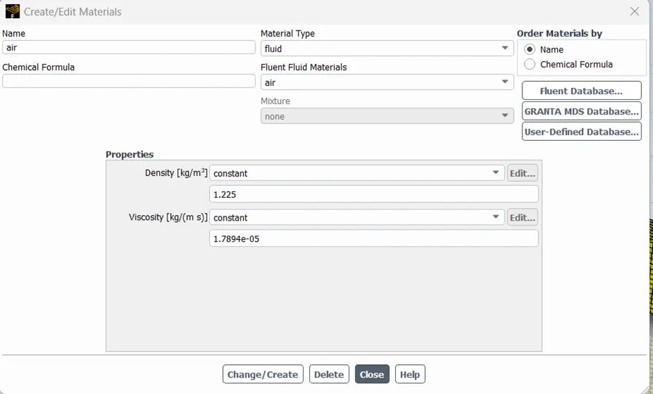
Material Properties
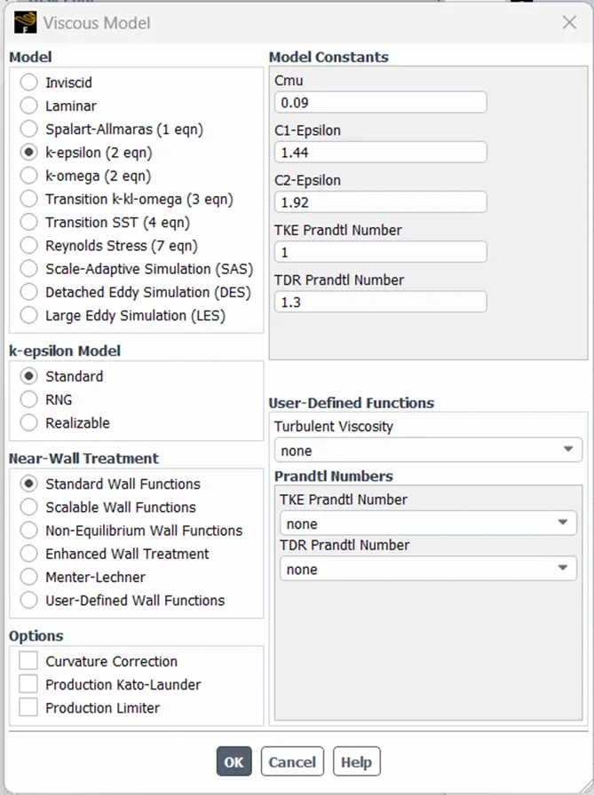
Viscous Model
Hybrid Initializa
Analysis of all the cases
Case 1
1.1 Description of the case 1
|
Description |
Values |
|
Flow type |
Steady state, density-based solver |
|
Turbulence \ Viscous model |
K- Epsilon |
|
Inlet Velocity |
25 m/s |
|
Y+ |
1130 |
|
Number of enclosures |
1 |
|
Total Number of elements |
84327 |
|
Total layer Thickness |
NA |
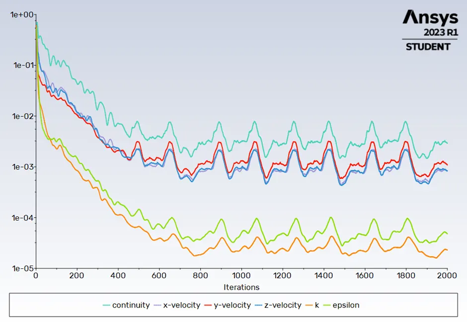
1.2 Line plot of Residual versus the iteration
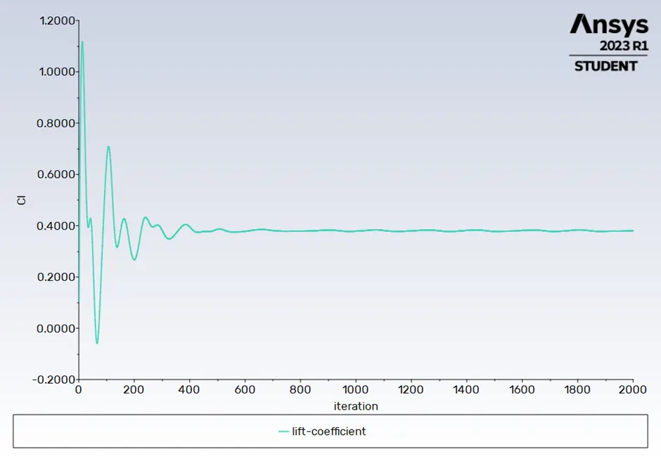
1.3 Line plot of lift coefficient versus the iteration
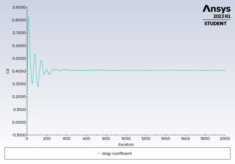
1.4 Line plot of Drag coefficient versus the iteration
1.5 Result table
|
Description |
Values |
|
Lift Coefficient |
0.38028377 |
|
Drag Coefficient |
0.40723413 |
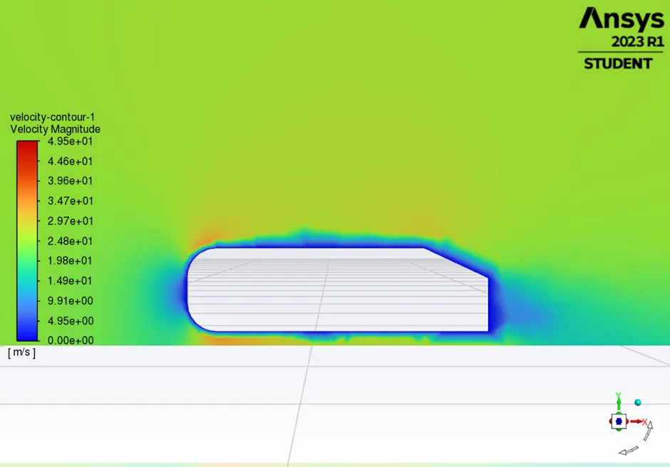
1.6 Contour plot of velocity Magnitude
1.7 Contour Plot of Static Pressure
1.8 Vector plot of velocity Magnitude
Case 2
2.1 Description of the case 2
|
Description |
Values |
|
Flow type |
Steady state, density-based solver |
|
Turbulence \ Viscous model |
K- Epsilon |
|
Inlet Velocity |
25 m/s |
|
Y+ |
262 |
|
Number of enclosures |
2 |
|
Total Number of elements |
338806 |
|
Total layer Thickness |
0.0496496 |
|
Number of layers |
5 |
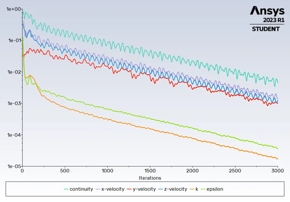
2.2 Line plot of Residual versus the iteration
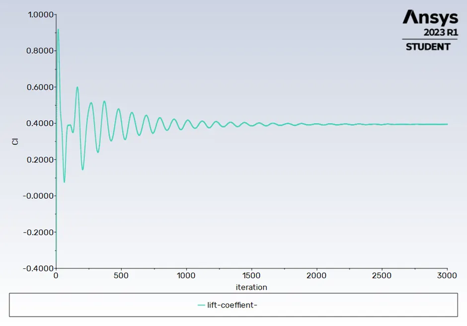
2.3 Line plot of lift coefficient versus the iteration
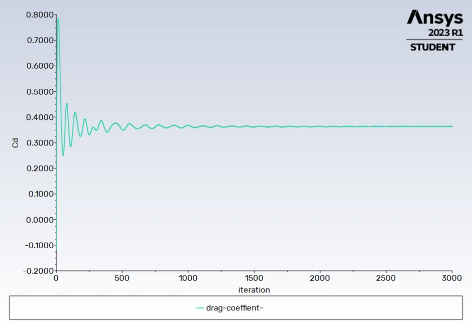
2.4 Line plot of Drag coefficient versus the iteration
2.5 Result table
|
Description |
Values |
|
Lift Coefficient |
0.39483361 |
|
Drag Coefficient |
0.36336941 |
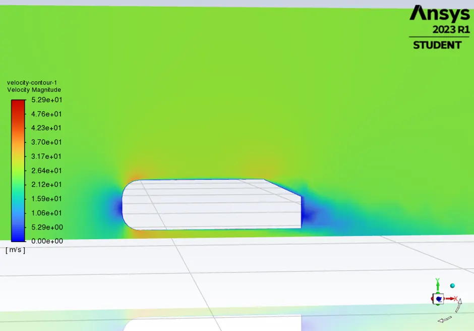
2.6 Contour plot of velocity Magnitude
2.7Contour Plot of Static pressure
2.8 Vector plot of velocity Magnitude
Case 3
3.1 Description of the case 3
|
Description |
Values |
|
Flow type |
Steady state, density-based solver |
|
Turbulence \ Viscous model |
K- omega SST |
|
Inlet Velocity |
25 m/s |
|
Y+ |
309 |
|
Number of enclosures |
2 |
|
Total Number of elements |
338806 |
|
Total layer Thickness |
0.0496496 |
|
Number of layers |
5 |
3.2 Line plot of Residual versus the iteration
3.3 Line plot of lift coefficient versus the iteration
3.4 Line plot of Drag coefficient versus the iteration
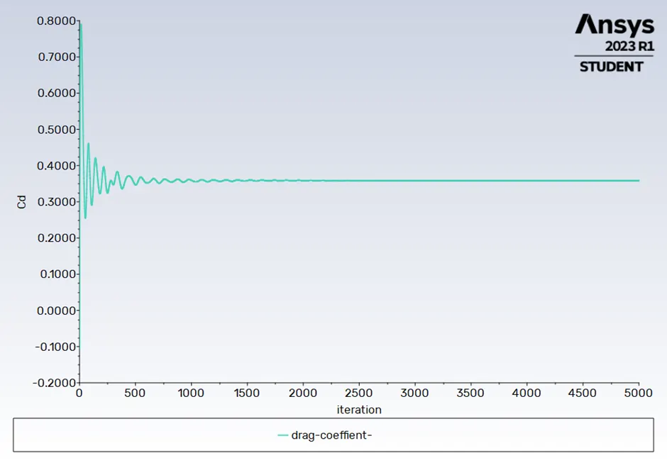
3.5 Result table
|
Description |
Values |
|
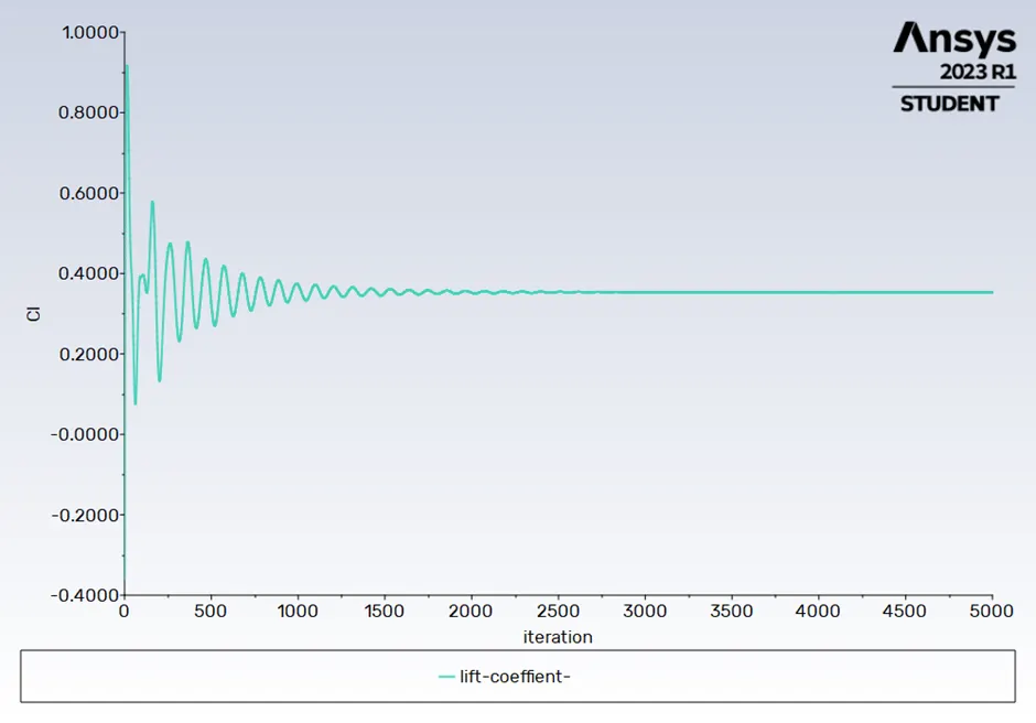
Lift Coefficient |
0.35339356 |
|
Drag Coefficient |
0.35856534 |
3.6 Contour plot of velocity Magnitude
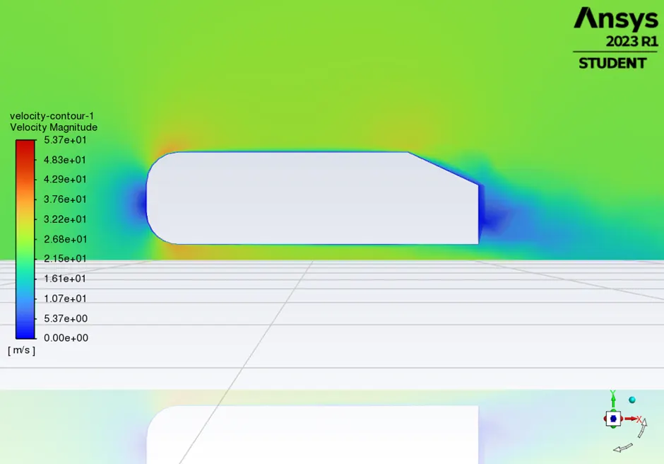
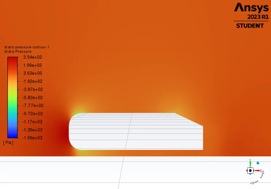
3.7 Contour Plot of Static pressure
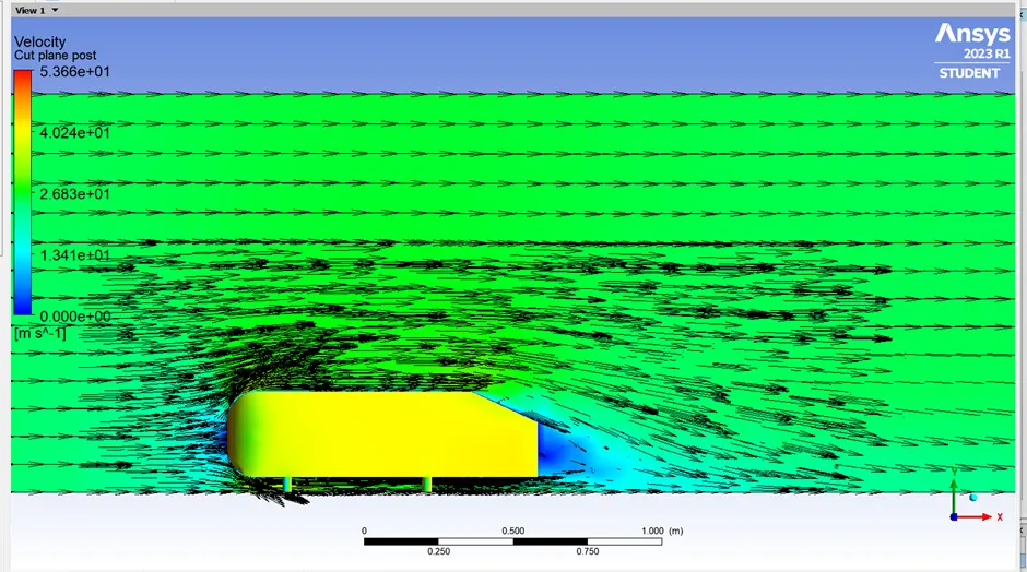
3.8 Vector plot of velocity Magnitude
Case 4
4.1 Description of the case 4
|
Description |
Values |
|
Flow type |
Steady state, density-based solver |
|
Turbulence \ Viscous model |
K- omega SST |
|
Inlet Velocity |
25 m/s |
|
Y+ |
250 |
|
Number of enclosures |
2 |
|
Total Number of elements |
426681 |
|
Total layer Thickness |
0.003582 |
|
Number of layers |
6 |
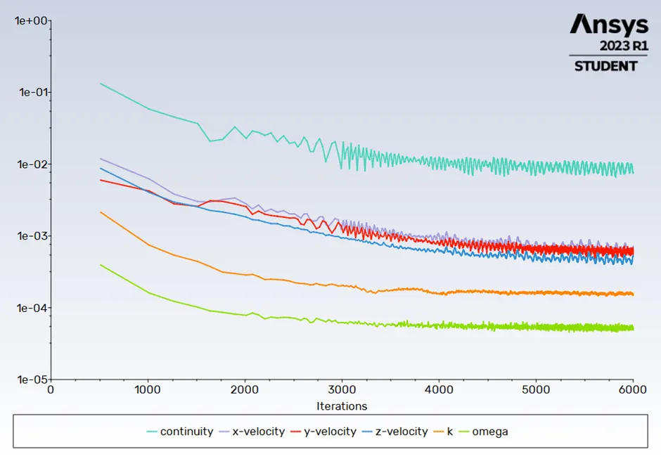
4.2 Line plot of Residual versus the iteration
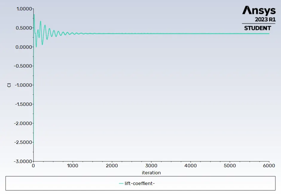
4.3 Line plot of lift coefficient versus the iteration
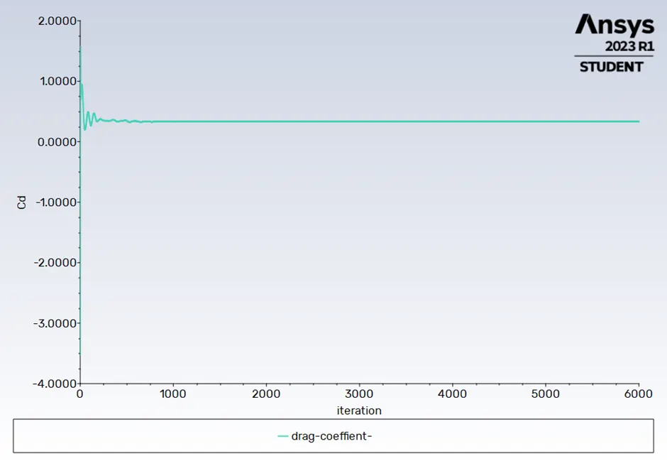
4.4 Line plot of Drag coefficient versus the iteration
4.5 Result table
|
Description |
Values |
|
Lift Coefficient |
0.34725825 |
|
Drag Coefficient |
0.33276102 |
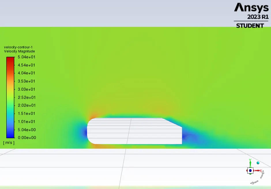
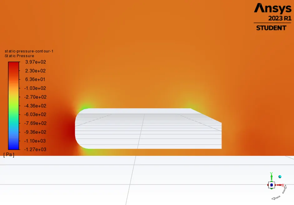
4.6 Contour plot of velocity Magnitude
4.7 Contour Plot of Static pressure
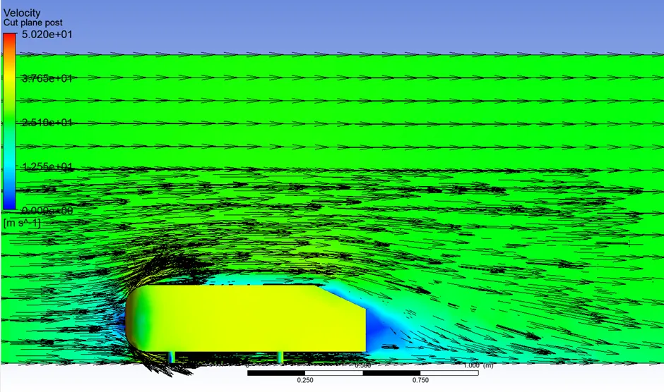
 4.8 Vector plot of velocity Magnitude
Case 5
5.1 Description of the case 5
Element size of outer enclosure is 0.1m and inner enclosure is 0.045m
|
Description |
Values |
|
Flow type |
Steady state, density-based solver |
|
Turbulence \ Viscous model |
K- omega SST |
|
Inlet Velocity |
25 m/s |
|
Y+ |
182 |
|
Number of enclosures |
2 |
|
Total Number of elements |
500749 |
|
Total layer Thickness |
0.002866 |
|
Number of layers |
6 |
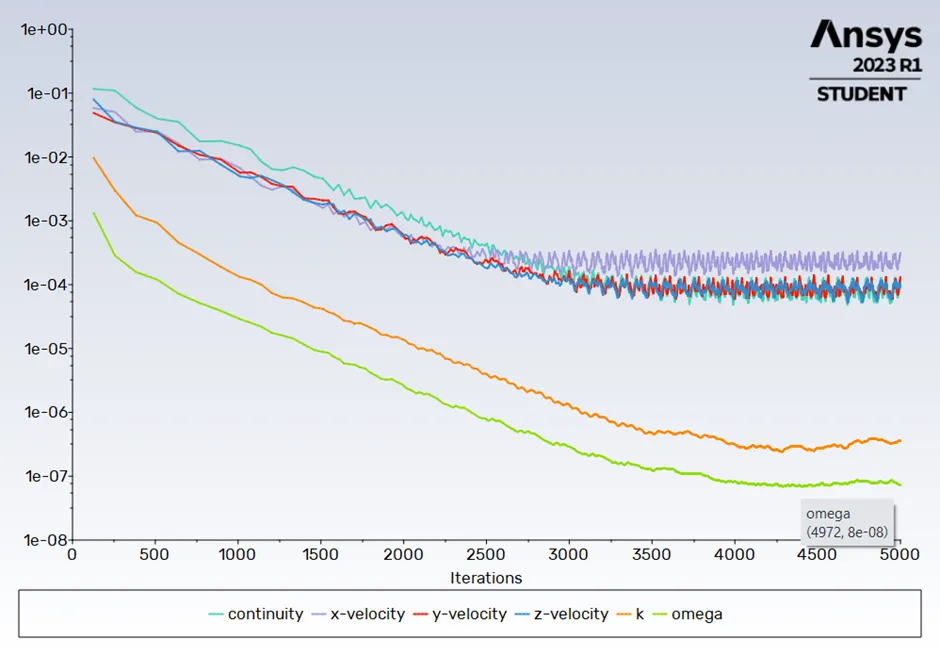
5.2 Line plot of Residual versus the iteration
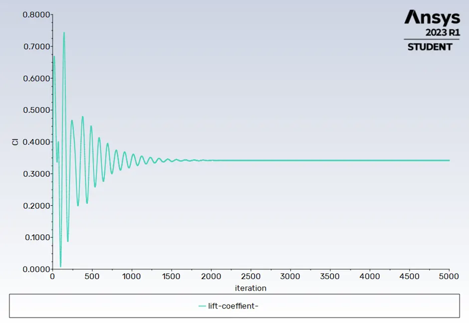
5.3 Line plot of lift coefficient versus the iteration
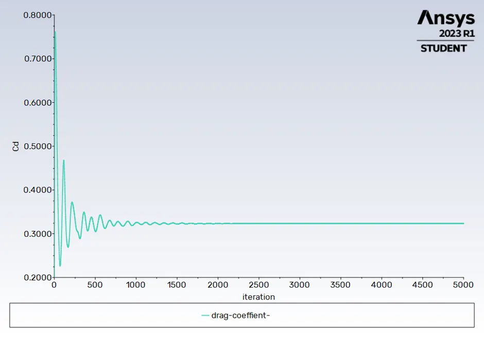
5.4 Line plot of Drag coefficient versus the iteration
5.5 Result table
|
Description |
Values |
|
Lift Coefficient |
0.34174889 |
|
Drag Coefficient |
0.32317101 |
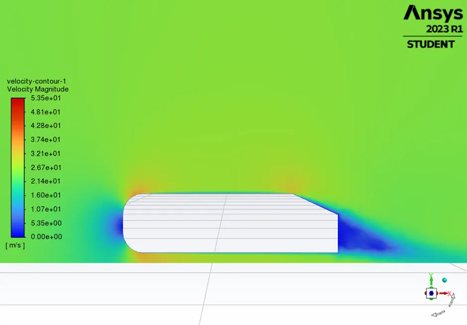
5.6 Contour plot of velocity Magnitude
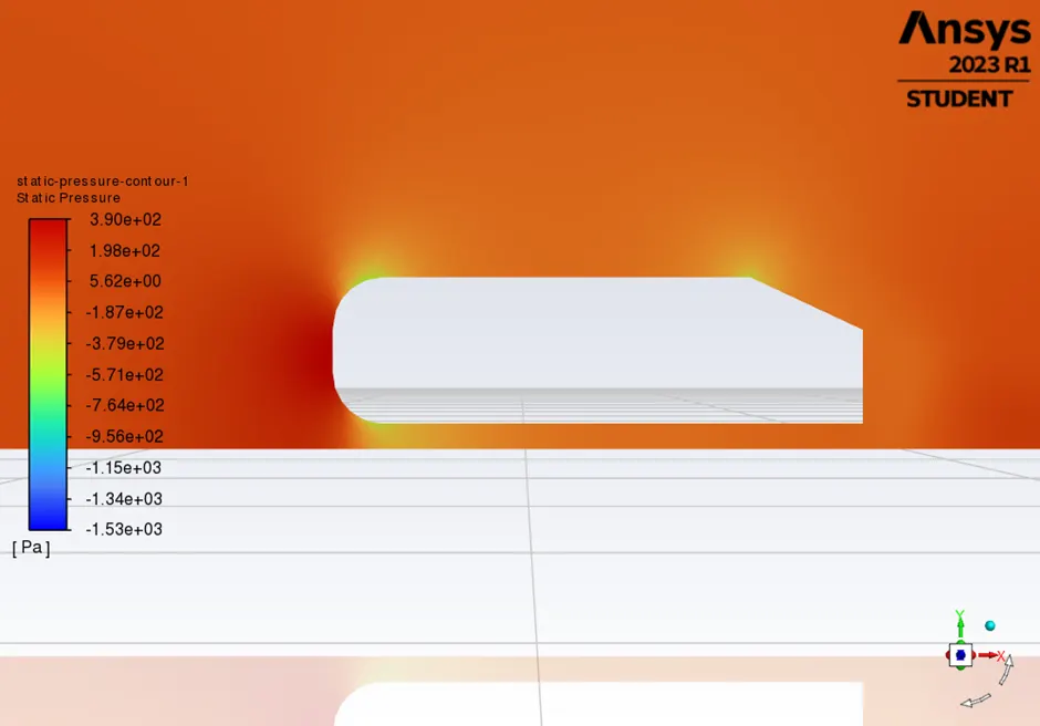
5.7 Contour Plot of Static pressure
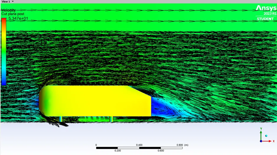
5.8 Vector plot of velocity Magnitude
Conclusion
1.coefficient of drag and lift
|
Cases |
Cell count |
Coefficient of Lift |
Coefficient of Drag |
|
Case 1 K- Epsilon |
84327 |
0.38028377 |
0.40723413 |
|
Case 2 K- Epsilon |
338806 |
0.36336941 |
0.39483361 |
|
Case 3 K omega |
338806 |
0.35339356 |
0.35856534 |
|
Case 4 K omega |
426681 |
0.34725825 |
0.33276102 |
|
Case 5 K omega |
500749 |
0.34174889 |
0.32317101 |
When free stream of air flow over the Ahmed body, the pressure at front of body increases, mean time air follow the boundary layer of the body but at the end flow separation takes place due to this wake region will be created. In wake region air circulation will take place due to this velocity will increase and pressure will decrease drastically. So, point of separation is more contribution to the drag force. More attached the flow over the body surface lesser the wake region.Referring to the above table, more refined mesh gives very good result. We can see wake region and vector very clearly. More finer mesh decrease the drag and lift of the Ahmed body.