Week 3 - External flow simulation over an Ahmed body.
Aim :
1.Describe Ahmed's body and its importance.
2.Explain the reason for the negative pressure in the wake region.
3.Explain the significance of the point of separation.
Objectives:
1. Plot Velocity and pressure contours.
2. The drag coefficient plot for a refined case. ( For velocity of 25m/sec, the drag coefficient should be around 0.33).
3. The vector plot clearly showing the wake region.
4. Perform the grid independency test and provide the values of drag and lift with each case.
What is Ahmed body and its importance?
The Ahmed Body was first created by S.R. Ahmed in his research “Some Salient Features of the Time-Averaged Ground Vehicle Wake” in 1984. Since then, it has become a benchmark for aerodynamic simulation tools.
The Ahmed body represents a simplified, ground vehicle geometry of a bluff body type. Its shape is simple enough to allow for accurate flow simulation but retains some important practical features relevant to automobile bodies. This model describes how to calculate the turbulent flow field around a simple car-like geometry using the Turbulent Flow, k-epsilon interface. Once the numerical model in validated, it is used to design new models of the car.
Importance of Ahmed Body :
The drag coefficient quantifies the resistance of an object in a fluid environment. It is not an absolute constant for a body’s shape because it varies with the speed and direction of flow, object shape and size, and the density and viscosity of the fluid. The lower the drag coefficient of an object, the less aerodynamic or hydrodynamic drag occurs. In terms of a car, the lower the drag coefficient, the more efficient the car is. As well as affecting the top speed of a vehicle, the drag coefficient also affects the handling. Cars with a low drag coefficient are sought after, but decreasing the drag drastically can reduce the downforce and lead to loss in road traction and a higher chance of car accidents.
There are certain ways to modify a car to optimize its aerodynamics and decrease the drag coefficient. To streamline the exterior, you can remove certain aftermarket items such as the roof rack, mud flaps, spoilers, and radio antenna. Professional car racers also take off their windshield wipers and side mirrors, but this isn’t recommended for the average driver! You can also add wheel covers, a partial grille block, an under tray, fender skirts, and a modified front bumper to improve the drag coefficient and make your car stand out in the process.
Reason for negative pressure in the wake region:
The path lines showing the exact circular motion or vorticity generation just at the rear end of the car. The separation takes two regions of distribution. One at the upper part of the rear and the other at the lower part of the rear end.
The path lines show about the nature of the fluid interaction with the rear end of the Ahmed body which here shows that the fluid just after leaving the contact from the slope still possess the momentum in it and the fluid particles near to the surface almost show the no-slip region which means the very least possible velocity of the fluid particles is in contact with the slope and base of the rear part. Thus the fluid particles away from the rear region having the higher pressure beside the wake region try to approach from the higher pressure region to the lower pressure region thus creating a circularity exactly in the wake region created.
The body penetrating the fluid creates a region of emptiness just beside its end due to the nature of the geometry of the body here which can be seen least in case of a perfectly streamlined shaped body. This emptiness created is a low-pressure region towards which the fluid column exactly behind the wake region which of atmospheric pressure tries to fill the space thus dragging the fluid column with it thus creating the region of vorticity. This also results in the huge pressure gradient in the region exactly rear of the body creating the –ve pressure at the end. Also, this is the layman’s reason why there is negative gauge pressure in the wake region.
Singnificance of the point of Sepration
Separation of flow is said to occur when the direction of the flow velocity near the surface is opposed to the direction of the free stream velocity, which means (du/dy) ≤ 0. Such a situation arises when there is a negative pressure gradient near the wall.
Boundary layer separation is always observed to take place at a point on the surface of an obstacle where the pressure gradient is adverse. Boundary layer separation is an important physical phenomenon because it gives rise to a greatly enhanced drag force acting on a non-streamlined obstacle placed in a high Reynolds number flow.
Downstream of the separation point, vortices often form, resulting in a turbulent flow. A flow separation is particularly dangerous on the wings of an aircraft, as this also causes a loss of lift and the aircraft is in danger of crashing. In aviation such a dangerous flow separation is called stall.
The separation of the boundary layer reduces the skin friction drag, but the pressure drag increases much more, so that the overall drag significantly.
Separation of turbulent boundary layers
The flow around a body can not only be laminar, but also turbulent at increased Reynolds numbers. In general, a laminar flow around the body should be aimed for, since this reduces flow losses to a minimum. However, this is only the case if it is ensured that no boundary layer separation occurs. If, on the other hand, this cannot be ensured, then turbulent boundary layers should be aimed for. This may sound a paradox, but a turbulent boundary layer can usually follow the profile of a body longer than a laminar flow. The reason for this is the increased transport of momentum between the fluid layers, which leads to a steeper velocity profile within the boundary layer.
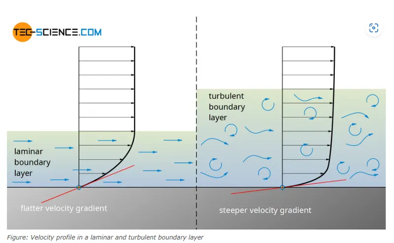
With a turbulent boundary layer, the velocity in the y-direction increases faster than with a laminar boundary layer. This means a larger velocity gradient near the wall and thus higher velocity components in the boundary layer. The resulting higher kinetic energy of the boundary layer can counteract the adverse pressure gradient more, so to speak.
In the case of a turbulent boundary layer, the separation point thus shifts downstream. The turbulent wake becomes narrower with the shifting of the separation point. This reduces the flow losses and thus the pressure drag, which ultimately results in a reduction of the overall drag.
Turbulent boundary layers adhere longer to the surfaces of the body around which flow occurs. The (pressure) drag is significantly lower. If there is a risk of flow separation, turbulent boundary layers should be aimed for.
This fact is taken advantage of, for example, with golf balls. The dimples in the golf ball cause vortices and lead to a turbulent flow around the golf ball. The separation point shifts downstream and the drag is reduced to only a quarter, which makes the golf ball fly much further.
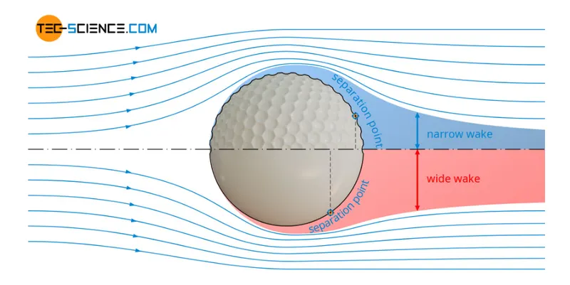
Figure: Dimples on a golf ball to create a turbulent flow around it
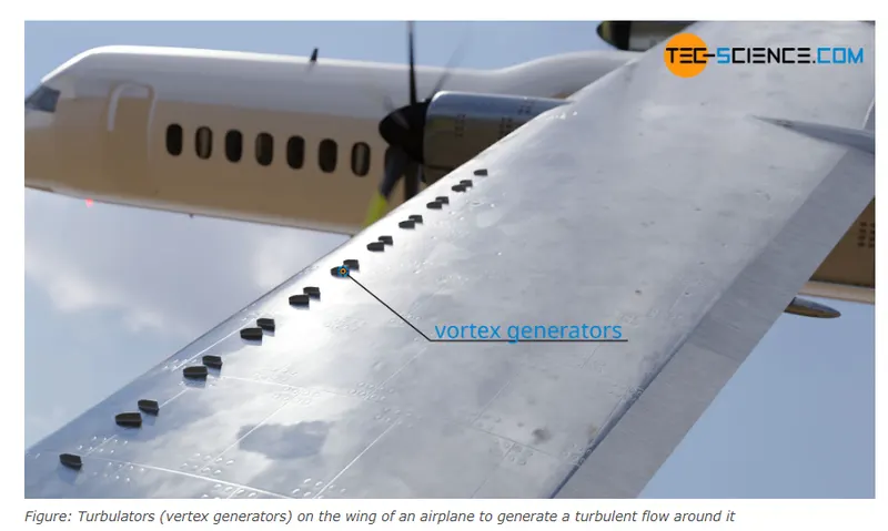
So-called turbulators (vortex generators) on the wings of aircraft act in a similar way. Often many small vanes are mounted on the wing for this purpose. These vanes create a transition from a laminar to a turbulent flow. The turbulent boundary layer, which remains longer on the wing, not only reduces drag but also the risk of hard stall. Another possibility to achieve a targeted turbulent flow around wings is the use of so-called blast turbulators. Air is blown out through small holes in the wing. This also causes the laminar flow to change into a turbulent flow.
STEPS TO SOLVE:
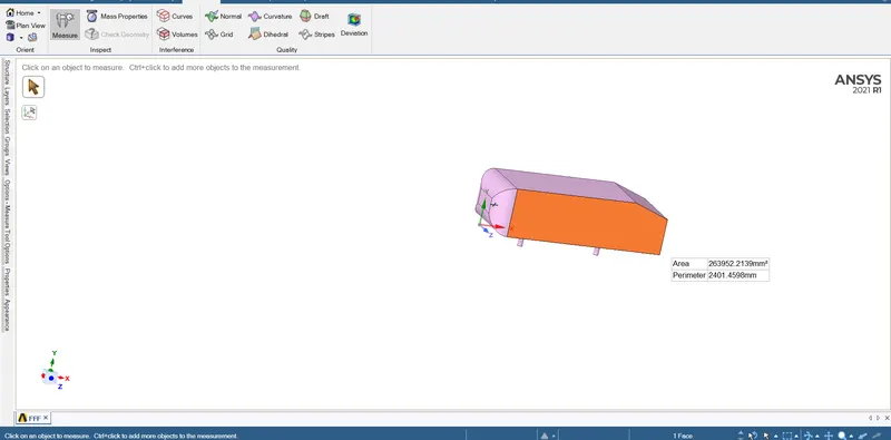
When opening model in geometry
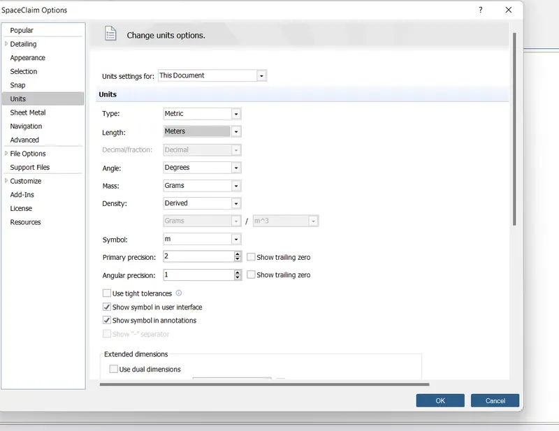
Unit changed from millimeter to meter
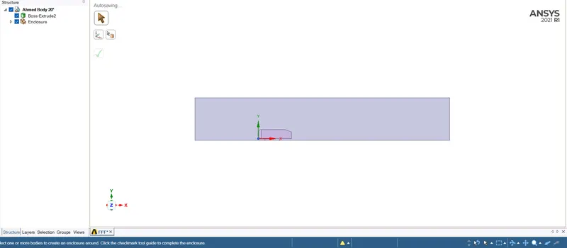
Outer enclousure created
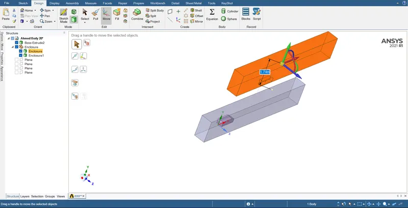
Splitted and moved the body by using Split Body command
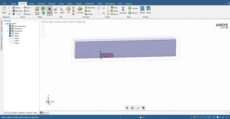
showing a cut section of model
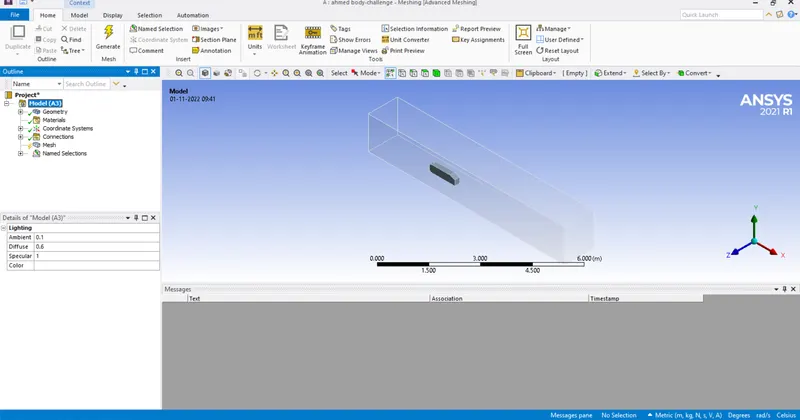
Opening model in mesh window
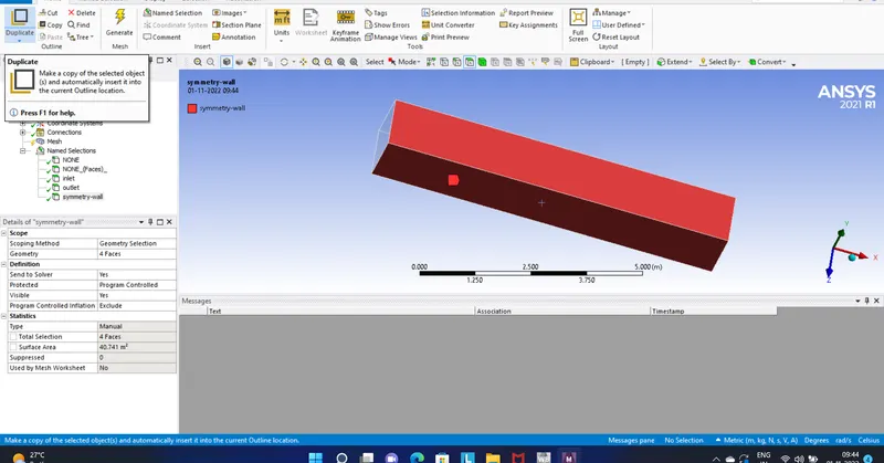
Given names for boundaries
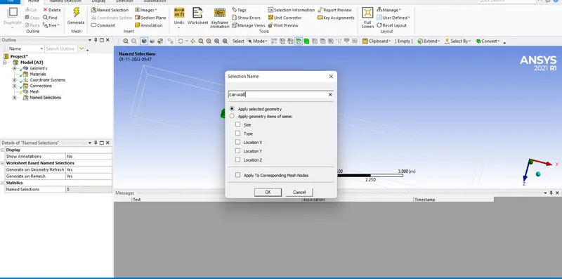
Giving naming to the Ahmed body
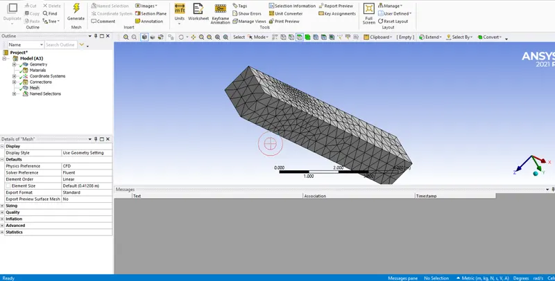
Created a basic mesh
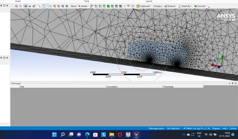
Mesh created inside the Ahmed body
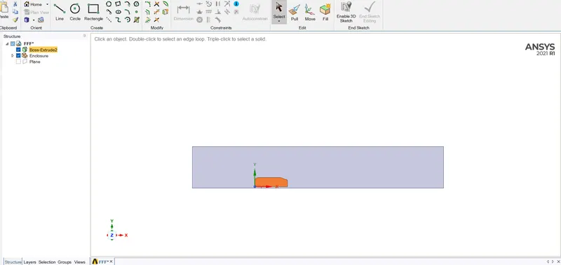
Ahmed body suppressed for physics
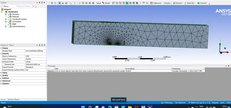
Then meshing done
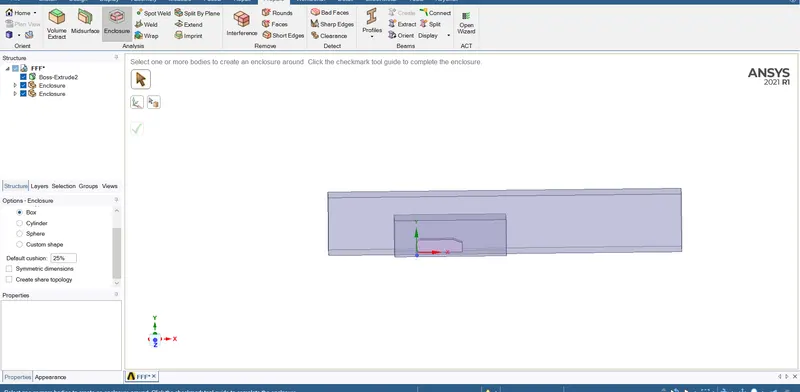
For the refinement intermediate enclousure created
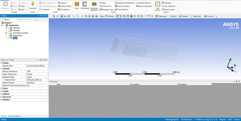
Agian opened in mesh window
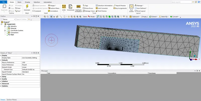
Created a defult mesh
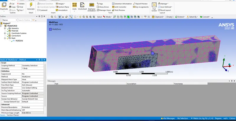
Creating hexahedral mesh
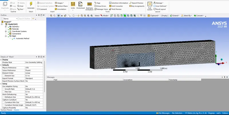
Hexahedral mesh created with Multizone
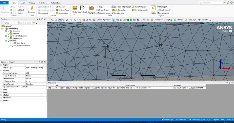
Shape of the supporting pillar is like a polygon
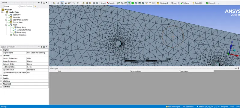
Support pillar made it as perfect circle
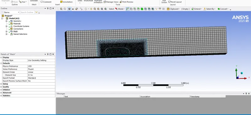
Hexahedral mesh created by using Multizone option
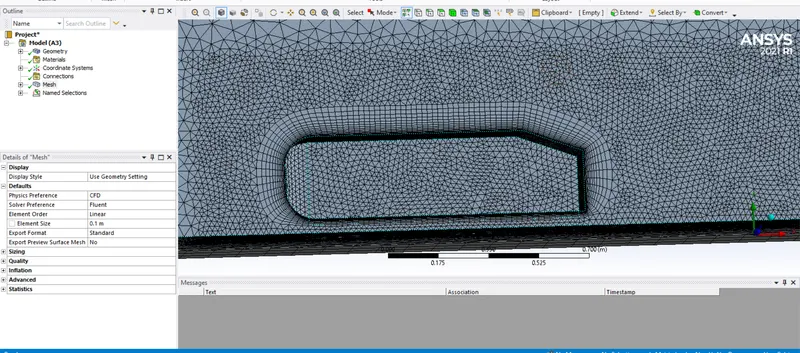
Inflation layer added based on yplus value
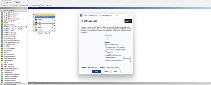
Opening the setup window
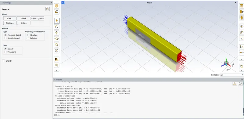
Performed mesh cheking
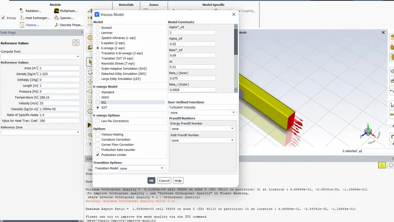
Using K-Omega SST Model
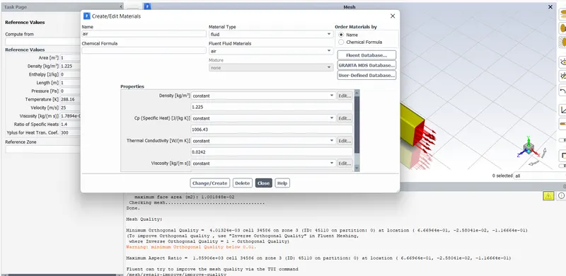
Material using is air
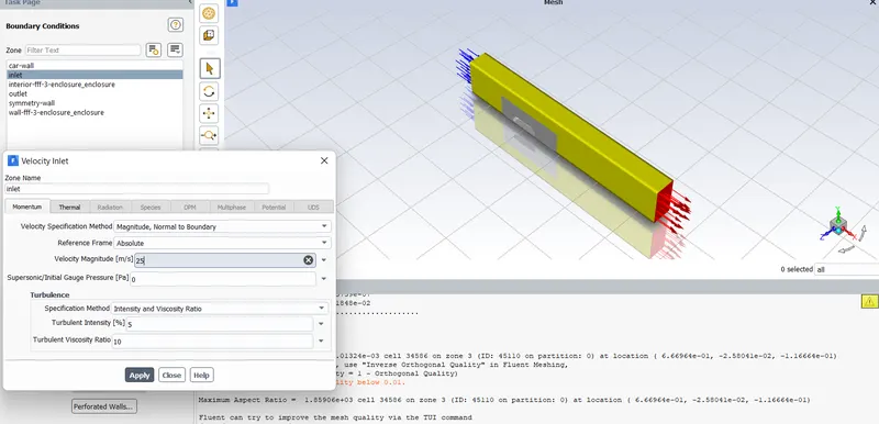
Giving inlet boundary conditions
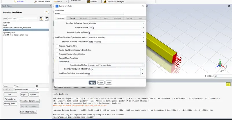
Giving outlet boundary condition
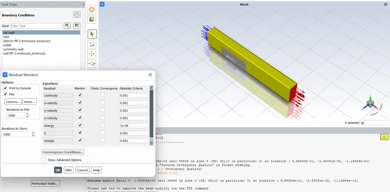
Unchecking the convergence criterias for running full number of iterations
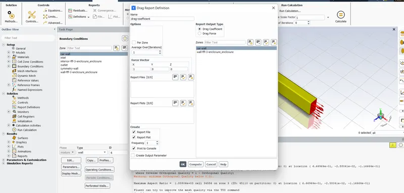
Setting up the drag coefficient
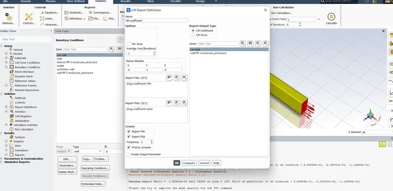
Setting up the lift coefficient
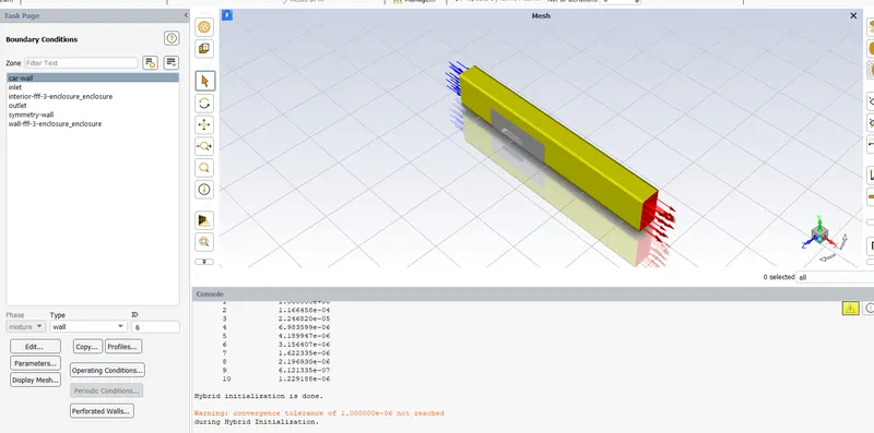
Hybrid Initialization done
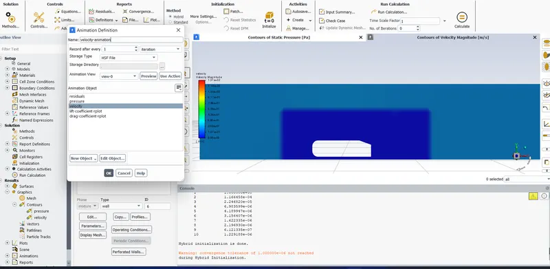
Creating velocity animation
RESULTS AND DISCUSSION:
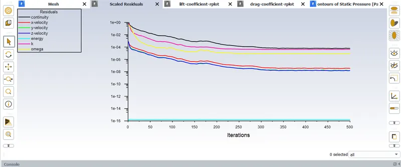
Showing residuals
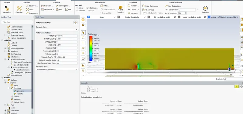
Showing Pressure contour
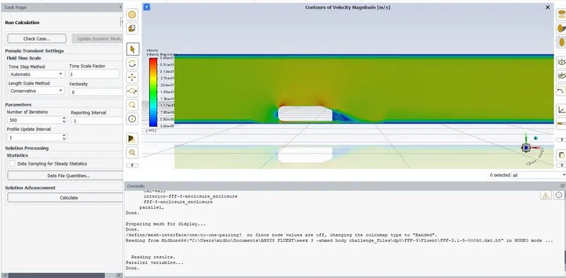
Showing velocity contour
From this it is clear that wake region is forming just behind the Ahmed body
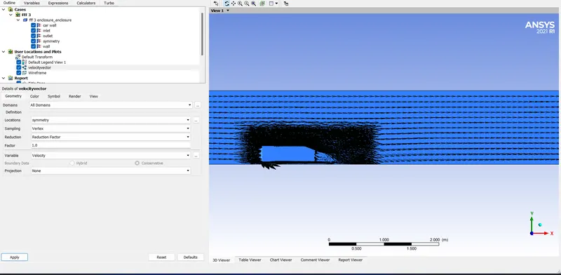
Showing Velocity vector plot
From this velocity vector plot the region of wake formation is very clear.
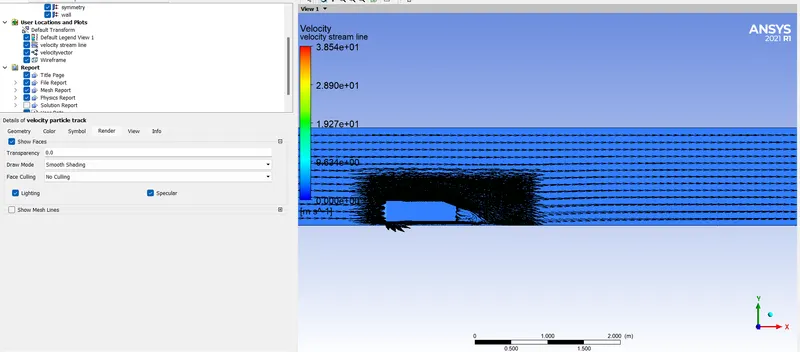
Showing Velocity vector plot , It clearly showing the wake region.
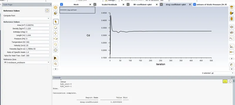
Showing plot of drag coefficient
From this we can understand that the drag coefficient is 0.3280
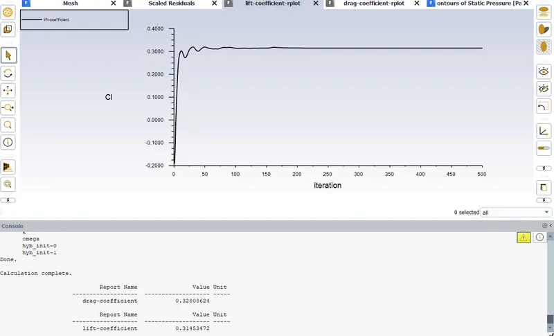
Showing plot of lift coefficient
From this we can understand that the lift coefficient is 0.3145
GRID INDEPENDANCE STUDY:
| Cases | Cell Count | Coefficent of Drag (Cd) | Coefficent of Lift (Cl) |
| (1) | 3,32,372 | 0.3280 | 0.3145 |
| (2) | 14,41,532 | 0.3327 | 0.3354 |
| (3) | 17,99,771 | 0.3346 | 0.2923 |
From the above table with the refinement of the mesh drag coefficient approaches closer to the analytical values that are because more cells are assigned at the boundary layer which results in more accurate results of drag coefficients.
Conclusion:
- High pressure is formed at the frontal area of the Ahmed body due to the loss of kinetic energy of the air.
- The adverse pressure gradient is created near the wake regions because of the flow separation which is occurring because of the geometry of the model. As a result flow separation alters the pressure gradient which in turn affects the drag and lift coefficients.
- In order to reduce the size of the wake region, detachment of the fluid should be farther away from the body which can be achieved by an increase in the slant angle.