Week 3 - External flow simulation over an Ahmed body.
AIM:
In this challenge need to use SpaceClaim to perform the operation and then you can use the symmetry boundary condition in fluent to perform the simulation.
Run the simulation for the velocity of 25 m/sec with the default air properties in fluent.
For this challenge, you will have to provide answers to the following questions:
Q1. Describe Ahmed's body and its importance.
Q2. Explain the reason for the negative pressure in the wake region.
Q3. Explain the significance of the point of separation.
Expected Results:
1. Velocity and pressure contours.
2. The drag coefficient plot for a refined case. ( For velocity of 25m/sec, the drag coefficient should be around 0.33).
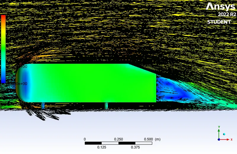
3. The vector plot clearly showing the wake region.
4. Perform the grid independency test and provide the values of drag and lift with each case.
INTRODUCTION AND PROCEDURE:
Open ansys workbench and drag and open fluid flow(fluent) and make it standalone system.
name it as the AHMED BODY.
now the double click the geometry and space claim is opened.
GEOMETRY:
The ahmed body model is opened in the spaceclaim interface,change the units in meter(m). in order to find the flow over the ahmed body the enclosure surface is needed.
So in the prepare tool bar by using the enclosure tool, the enclosure box is generated around the ahmed body.
The dimension of enclosure box is following :
Rear side - 5 m from the ahmed body
Front side - 2m from ahmed body
Bottom side - 0m from ahmed body
Top side - 1m from ahmed body
Now in design deck,by using the plane tool,the X,Y,Z planes of the ahmed body is created.
since the ahmed body is symmetry,so the selection mode is selected on the z plane.
the simulation and analysis is only carried over the ahmed body so the model is suppress for physics.
in order to set a fine and proper analysis of the flow over the model, the small enclosure is created.
the dimensions of the enclourse is;
rear side-1m ,from side-0.5 m, bottom side-0 m , top side=0.5 m.
to avoid the interfere between the two enclourse,the interference check is carriedout and overlap surfaces are removed.
and the planegeneration is carried,and the check of the overlap is checked by section mode.
these are the geometry process in the ahmed body.
MESHING:
After the geometry process the model is updated in the ansys workbench and the mesh is opened.
By selecting the front face of outer most enclosuer and name it as inlet - o., Rear face of the outer enclosure is outlet - o
rest of the four outer most enclosure walls are named as symmetric wall - o, and the whole outer enclosure is hide.
by selecting the front face of inner enclosure and name it as inlet - i., Rear face of the inner enclosure is outlet - i
rest of the four inner enclosure walls are named as symmetric wall - i, and the whole inner enclosure is hide.
By using box selection the whole ahmed body is selected and name it as car wall.
by using name selection tool the model is cut into half.
for the outer most enclosure in mesh - insert - method - multizones
In the details of mesh the element size is changed as 200mm and the maximum size = 200mm. then mesh is generated.
for the inner enclosure geometry is applied and sizing the element size is 50mm.
then all the faces of the inner enclosure is hide.now ahmed body is selected and the element size is 10mm
in order to get the fine analysis near the body so we inflation layer is needed.
in inflation layer -total thickness-max layers are 5 and maximum thickness is 12.5 mm.
and the generate mesh is applied in the model , then the fine refined meshed is apppered for the model.
then the refined mesh of the ahmed body is:
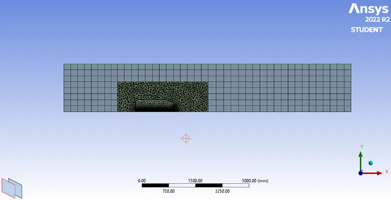
after complete all the meshing process of the model ,that is updated in the ansys workbench.
SETUP:
now the fluent is opened,by enable the double precision .
in setup physics change it as density based solver ,steady state , k-epsilon in physics and enabling the eneregy equation.
keep the air as the fluid .
now the boundary condition is applied,
inlet velocity =25 m/s.
and temperature as =300k.
and initalize hybrid.
in the result deck,a new plane is created in order to analysis the flow over the ahmed body .
this plane is created by using the cutplane-plane-point-origin as 0,0,0. and normal as 0,0,1.
and save it as create/display.
in order to analysis of the contour velocity and pressure.the contour -new-velocity contour-ok.save and display.
now back in the solution deck,the velocity animations is created by create-solution animations-change the view as required and use active and ok.
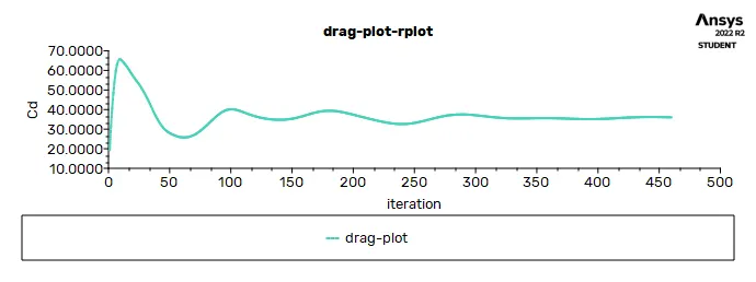
after all this ,the calculation is calculate with 460 iterations. AT 460 iterations the solution is converged.
then the contour velocity is shown:
the contour pressure of the flow of the ahmed body is:
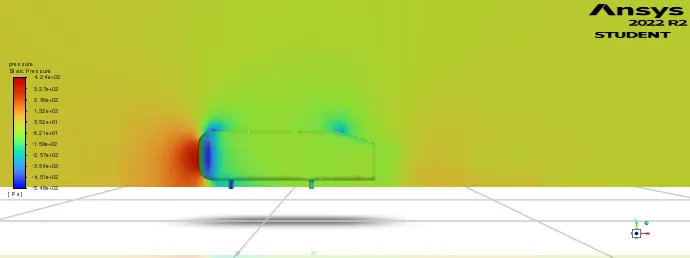
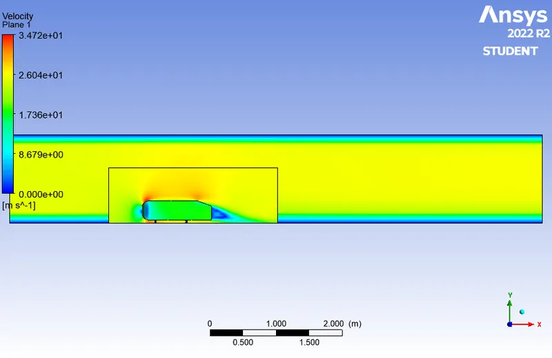
the velocity contour graph of the flow over thw ahmed body is:
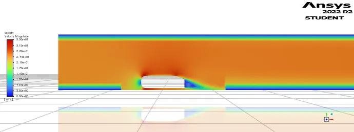
the velocity contour graph of the flow over the ahmed body:
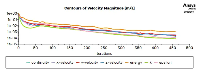
RESULT:
After the set set up results is updated in the ansys work bench, the result is opened in the ansys workbench.
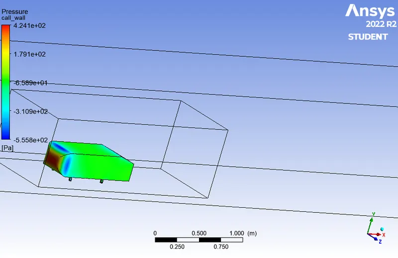
in the tool bar click on the car wall- then the constant is change as variablr and put pressure in that and click apply.
the pressure experienced by the ahmed body when 25m/s flow over it,
now the plane is inserted by using insert-plane-xyplane-apply.
the variable is changed for that plane as velocity and click apply.
the mesh lines are shown for that plance which is created .
the velocity over the ahmed body:
then the vector is created by means of creating vector
back to cutplane -render- deselect the mesh lines-vector-constant-colour(black).
the flow of the vector over a ahmed body is shown below:
after doing in order to get the data in the chart form, the lines are created by the help of the lines in the insert tab of the result.
in the same vector-geometry-point 1=2,0,0. pont2 =2,2,0. and apply..by this way the line is created.
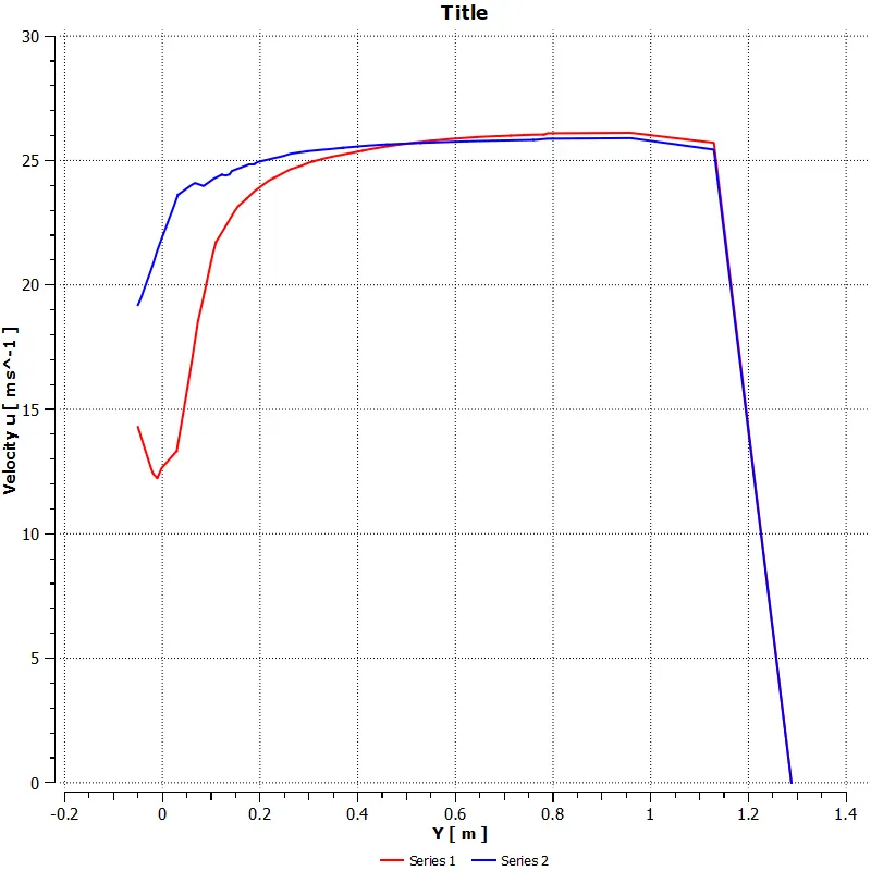
the two lines are created back to back and the chart is prepared for analysis of the ahmed body.
the graph chart is created by the insert -charts.
the graph is velocity in y-axis versus and y-component in x-axis:
CONCLUSION:
- AHMED BODY AND ITS IMPORTANCE:
The Ahmed body is a generic car body (a simplified vehicle model). The airflow around the Ahmed body captures the essential flow features around an automobile and was first defined and characterized in the experimental work of Ahmed body.
The Ahmed body generates the crucial features of flow pattern around a car for instance flow impinge-mentation and the displacement around the nose, relative uniform flow of air around the middle portion and flow separation along with the wake generation at the rear.
2.Explain the reason for the negative pressure in the wake region.
Due to the production of pressure drag being produced from flow separation, the pressure in the wake region is low. This is what is causing the vacuum.
3.significance of the point of separation.
The separation point is the point where the air stops "sticking" to an object that is moving through the air. When an object is moving through the air, the air molecules push back on it and resist the object's movement - this resistance is called pressure drag.
The drag coefficient plot for a refined case. ( For velocity of 25m/sec, the drag coefficient should be around 0.33).is,carried out for the ahmed body.
the graph plot of the drag is:
the vector plot of the ahmed body and forming drag in it is:
As the body is perfectly symmetric, the simulation by considering the only half body. This is the best practice where on the number of cells and get the results faster as well.
by this way the simulation of the ahmed body is carried out succesfully.