Week 3 - External flow simulation over an Ahmed body.
Aim: External flow simulation over an Ahmed body.
Objective: The objective of this project is to determine the aerodynamic forces on the Ahmed body such as drag and lift coefficient and to perform the grid independence test.
The expected results will include
1. Velocity and pressure contours.
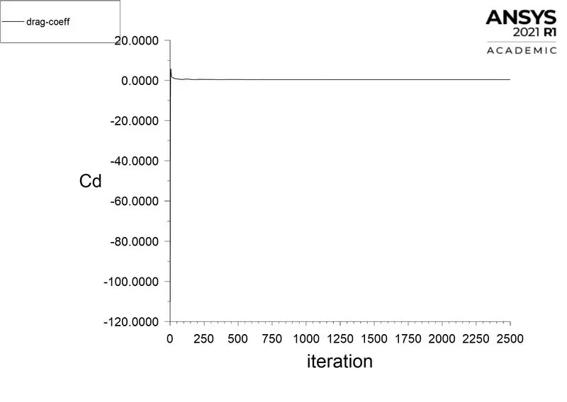
2. The drag coefficient plot for a refined case. ( For a velocity of 25m/sec, the drag coefficient should be around 0.33).
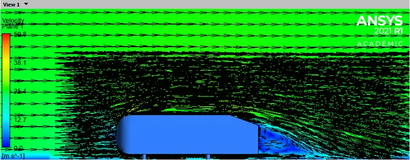
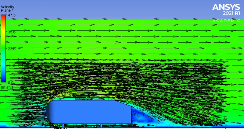
3. The vector plot clearly showing the wake region.
4. Perform the grid independence test and provide the values of drag and lift with each case.
Abstract
Ahmed body: The Ahmed body was first created by S.R. Ahmed. It is an important benchmark for aerodynamic simulation tools. It will be clearly shown in the sketch below that it has a length of 1.044 meters, the height of 0.288 meters and the width of 0.389 meters. It also has a 50 millimeter cylindrical legs attached to the bottom of the body and the rear surface which has a slant that falls of at 35 degrees.
The flow for the model is turbulent which is based on velocity and body length. For the default mesh size in ANSYS-FLUENT we will use k−ε model.
mportance of Ahmed body
The drag force is an important factor considering fuel consumption. As the drag force increases the fuel consumption also increases which in turn becomes expensive for the car owners. As the burning of fossil fuels becomes an issue, the manufacturers are pressing for fuel-efficient cars. One of the main factors considering the car is fuel-efficient or not is the car's geometry.
Complex shaped cars are very challenging to model and its difficult to quantify the aerodynamic drag computationally. The Ahmed body is a benchmark model widely used in the automotive industry for validating simulation tools.
Negative pressure in the wake region
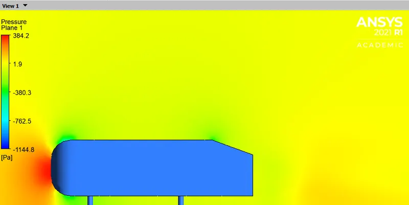
When the air moving over the vehicle is separated at the rear end, it leaves a large low-pressure turbulent region behind the vehicle which is known as the wake. This contributes to the formation of pressure drag which affects the vehicle performance.
When the vehicle is moving at a certain velocity the fluid imparts viscous force to the vehicle as long as it is in the viscous sublayer of the boundary. When the fluid reaches the rear end of the vehicle it gets detached from the surface of the body causing negative pressure in the wake region. The movement of the fluid around the vehicles depends on the geometry of the car and the Reynolds number.
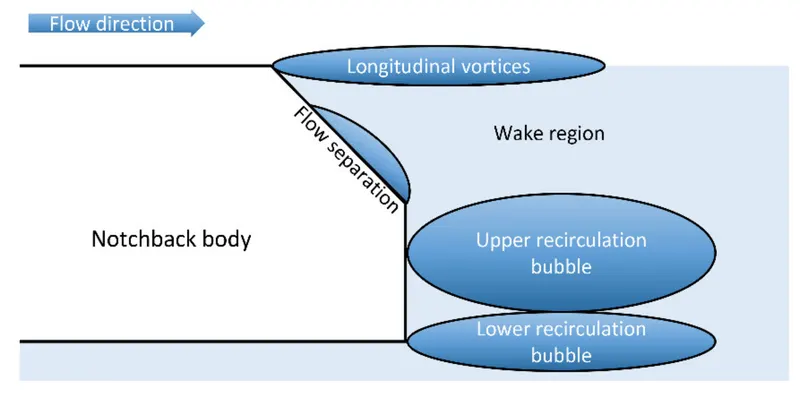
Significance of point of separation
The point of separation will occur when there is a discontinuity in the surface or a region of the negative pressure gradient (a sharp end or rear portion of the car).
When the flow is attached to the body of the vehicle the viscous force will increase which will increase the pressure and a decrease in velocity before the rear end of the vehicle. As soon as the air encounters the sharp turn causing the velocity to decrease resulting in the negative pressure region which is in the wake region. The recirculation region happens beyond the point of separation.
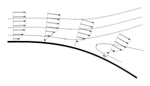
If the rate of change of pressure is large the mixing process will not occur and the boundary layer flow stops.
The above figure shows that at the point of turning the flow gets separated from the boundary layer and there is a region of recirculation after which the flow attaches itself to the boundary layer.
In order to reduce the separation of fluid from the boundary layer, it is advisable to have a smooth edge to reduce the effect of drag on the vehicle.
Importing the geometry into SpaceClaim
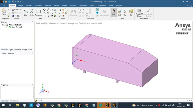
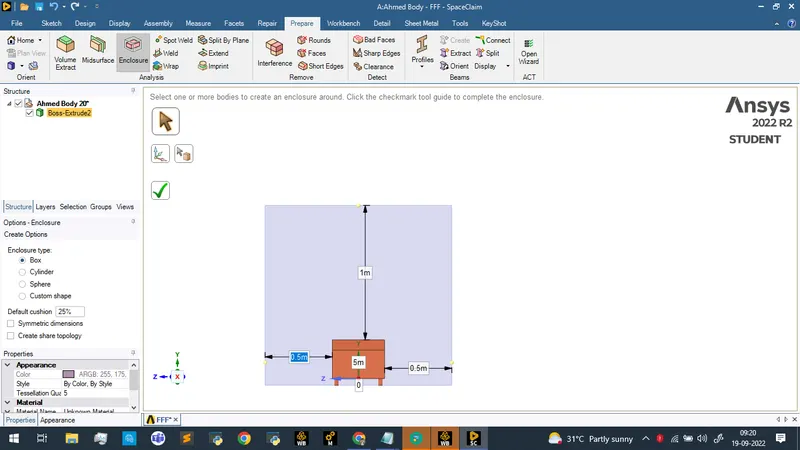
Since the analysis is to be performed over the body the mesh should be created externally and not inside . So the body is encompassed inside a surface using the enclosure algorithm.
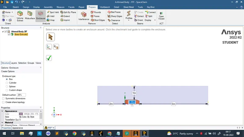
Adjusting the width parameters
Using the plane tool to create three sets of plane at the origin
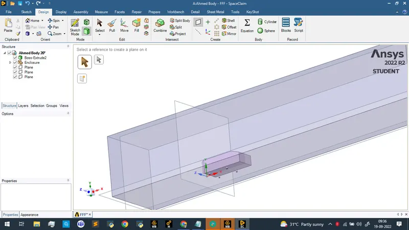
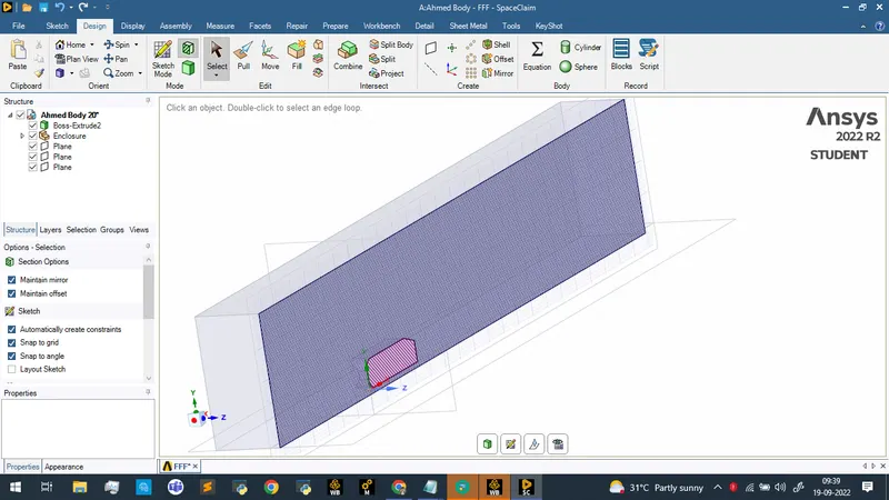
Selecting and using the section mode along the plane
Meshing
Open the meshing tool and create named selections
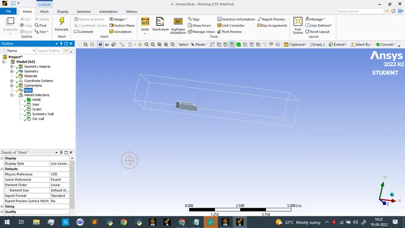
Generating a basic mesh with default element size
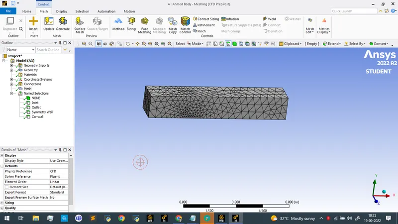
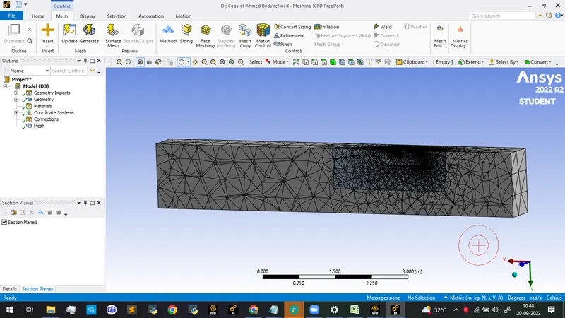
Viewing the model from top view and creating a section plane to cut the model in half
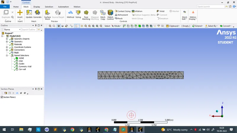
It can be seen that the inside surface of the Ahmed Body is meshed and as we considering external flow simulation this must be rectfied.
Since there are two copies of Ahmed Body we are supressing the physics for one
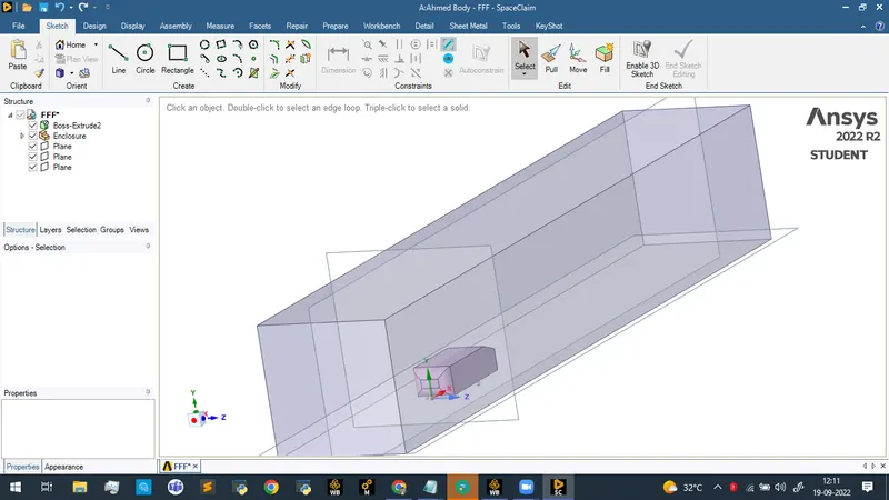
After supressing the physics and clearing the generated mesh data after which mesh regeneration is performed the mesh becomes
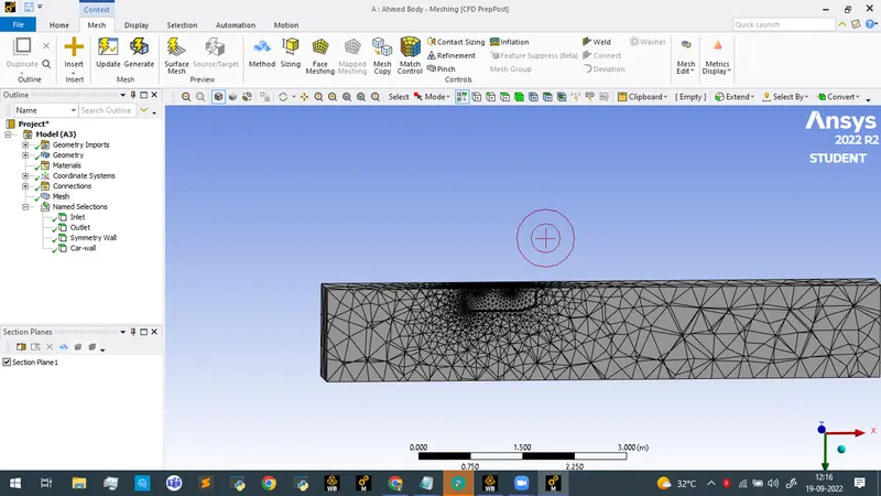
This is suitable for performing baseline simulation.
Creating a cut plane using point and normal option on the origin with normal on the z axis.
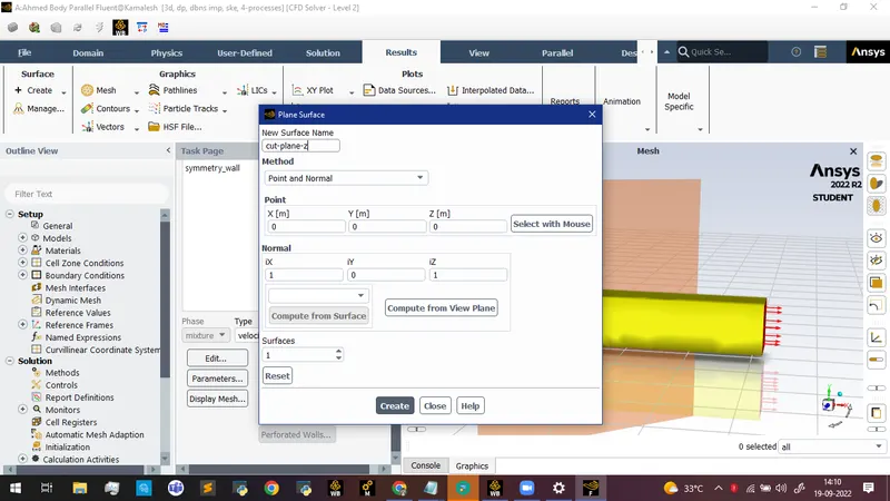
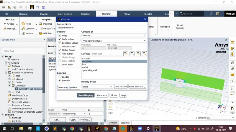
Creating a cut plane and defining the velocity contour along that plane
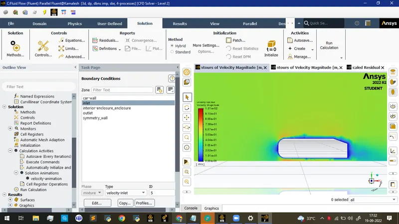
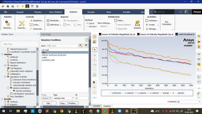
Running the simulation for 500 iterations
Contours of velocity magnitude
Scaled Residuals
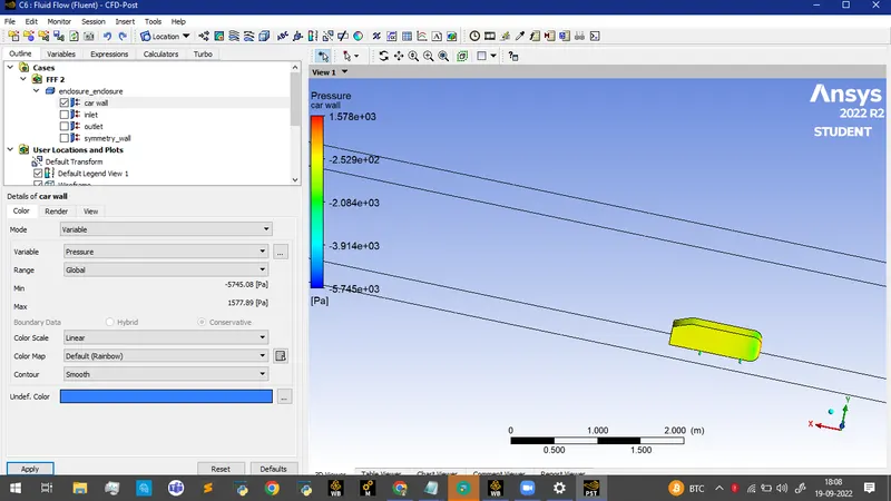
Pressure variation on the car wall
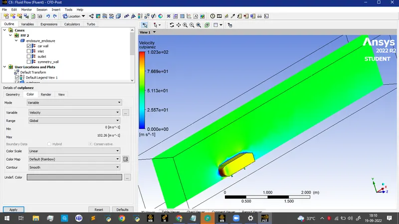
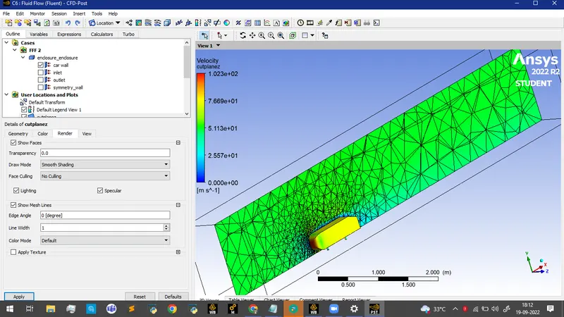
Velocity variation along the plane
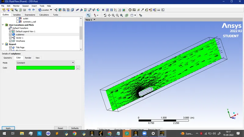
The vectors of velocity
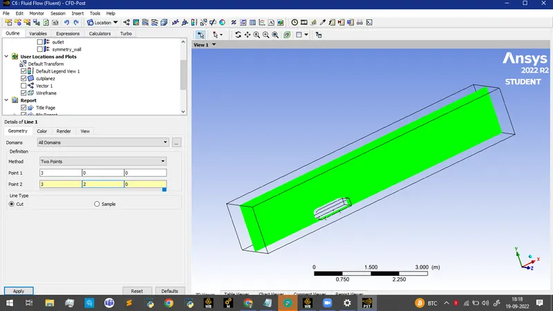
Creating a line with the cut feature enabled
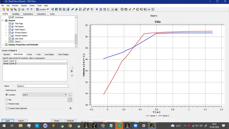
Creating a chart to depict velocity variation
Creating a refined mesh from the baseline simulation
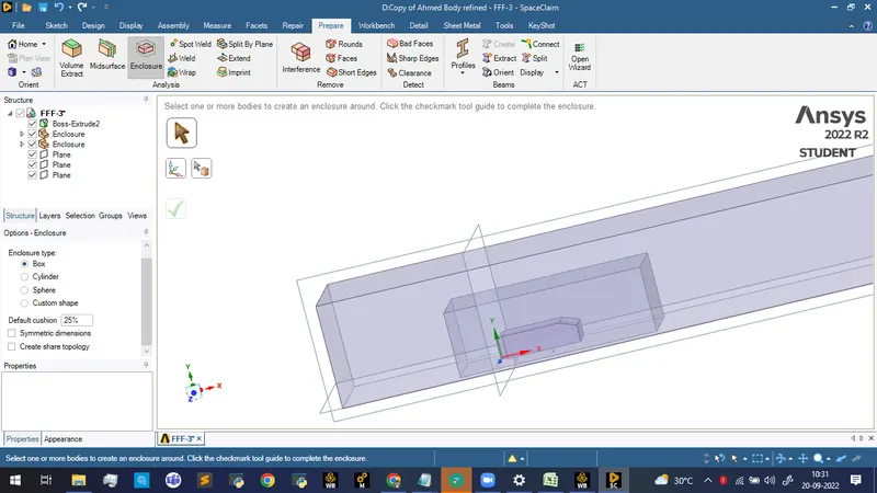
Creating the baseline mesh for the refined geometry
To rectify the overlapping surface
Creating a section view along the plane and running interference check to identify the overlap
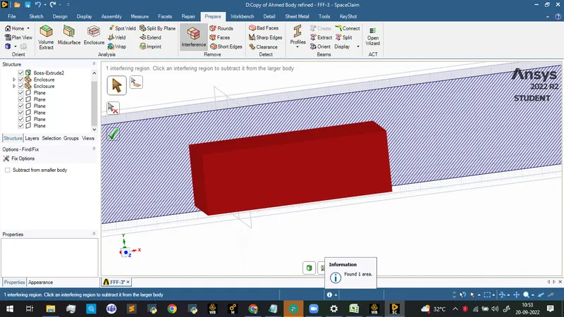
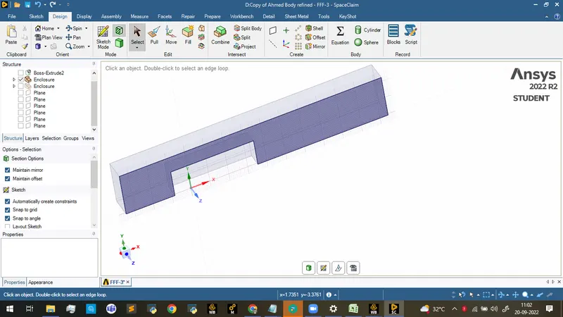
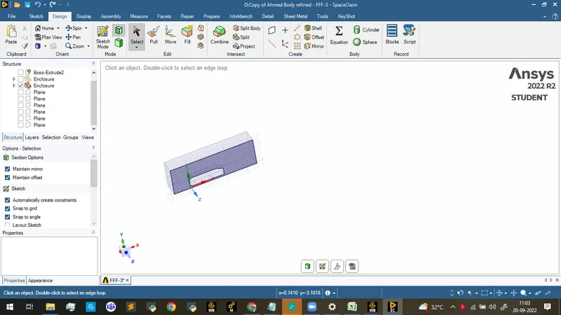
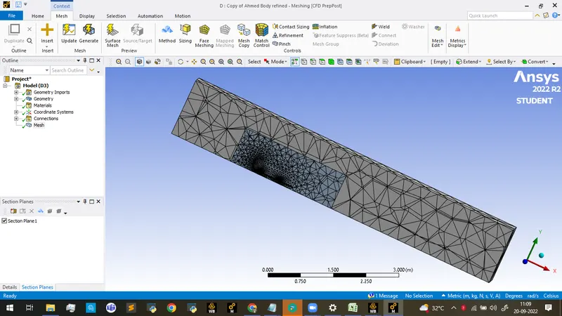
Mesh connectivity is perfect with no overlaps.
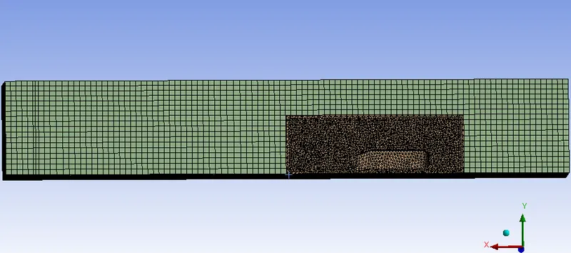
Creating a refined mesh
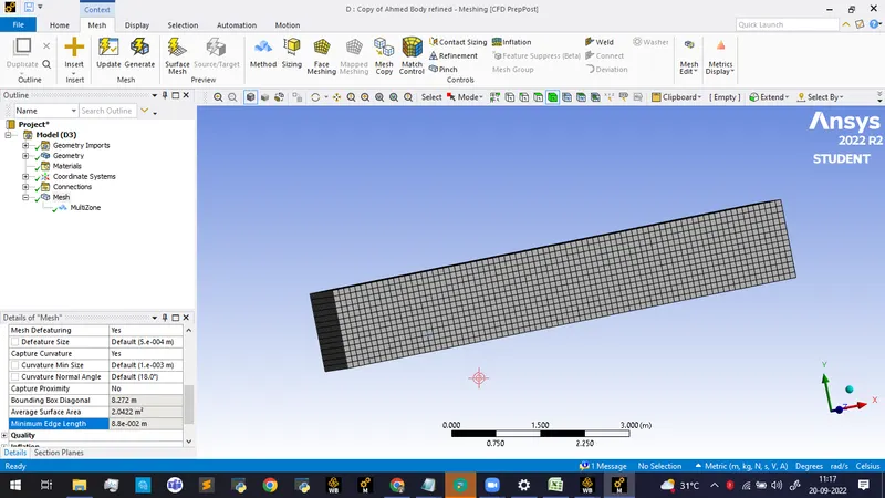
Creating a body sizing for the mesh for the inside surface
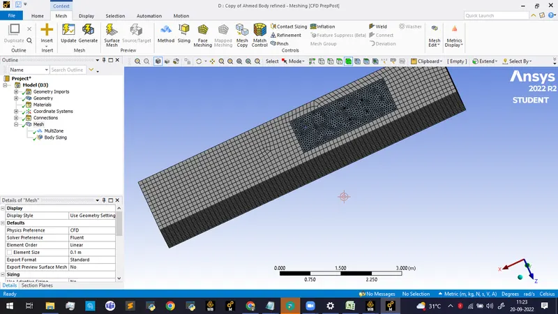
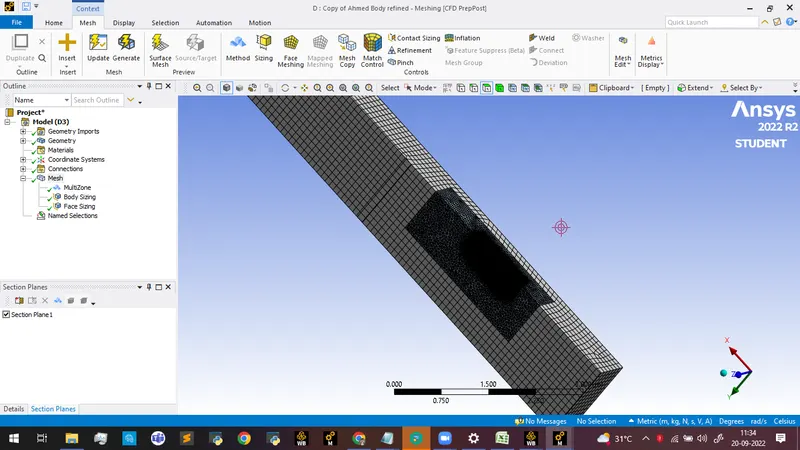
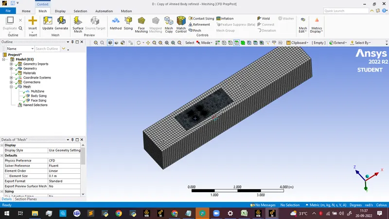
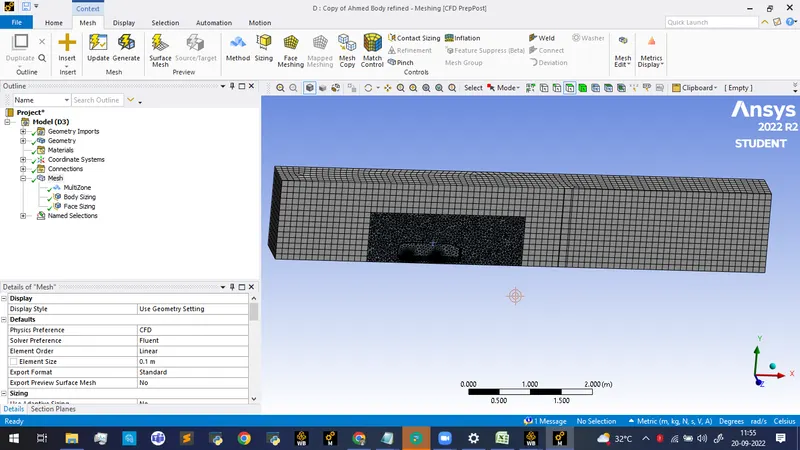
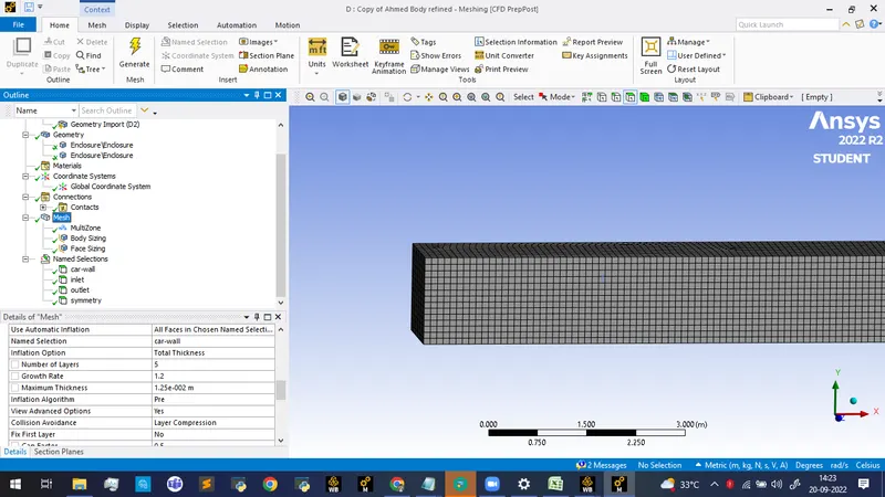
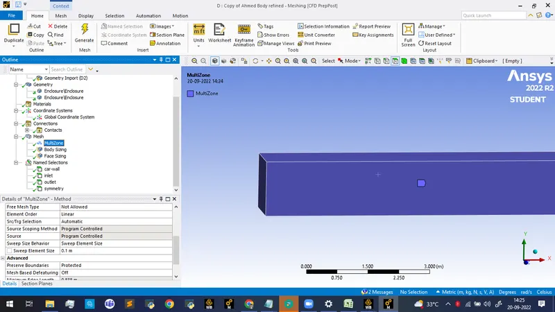
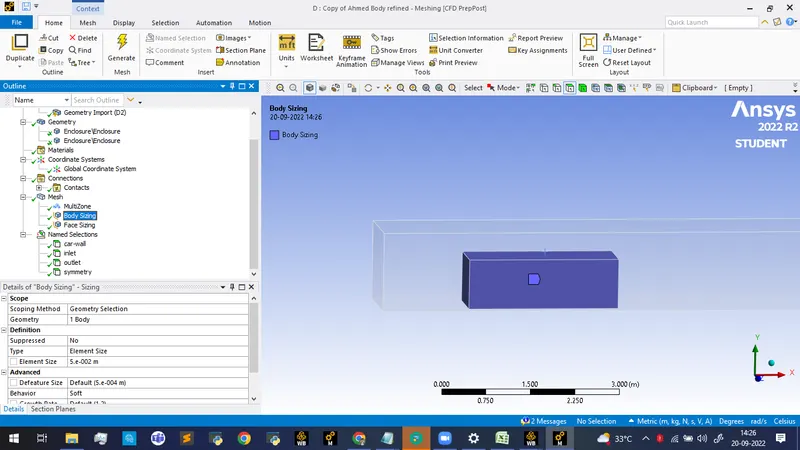
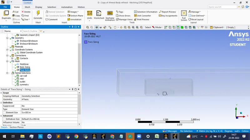
Mesh parameters
Inflation: Minimum thickness: 12.5 mm
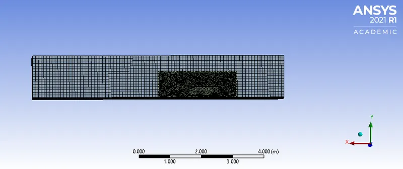
Multizone : Hexa with an element size of 100 mm.
Body sizing with an element size of 50 mm and face sizing for the car wall.
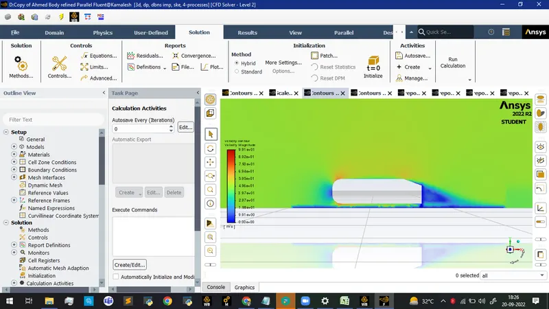
Contours of velocity distribution
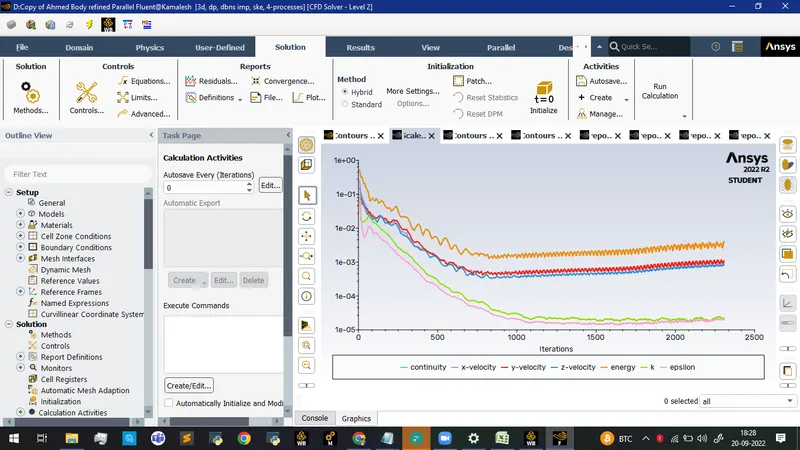
Scaled Residuals
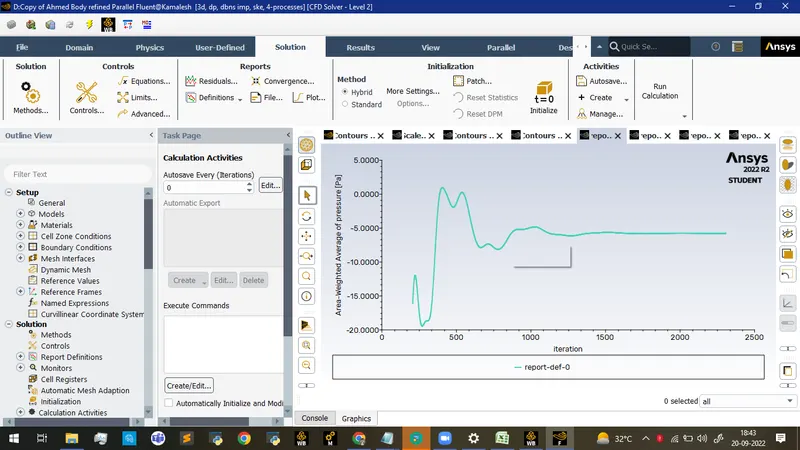
Area weighted average of pressure
Area weighted average of velocity magnitude
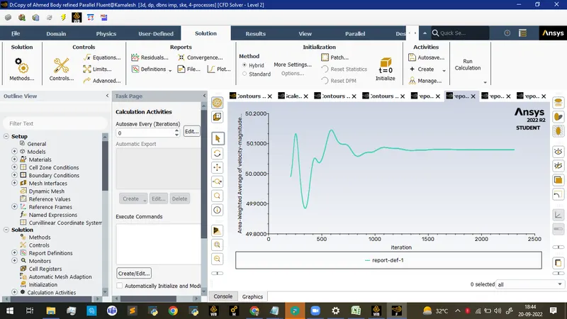
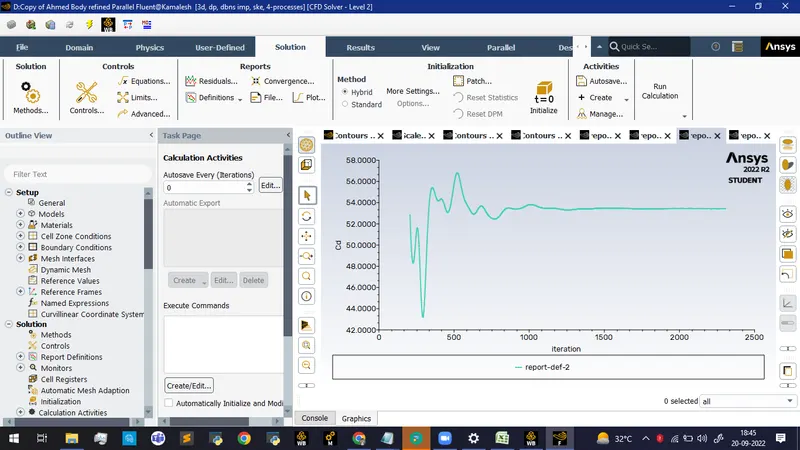
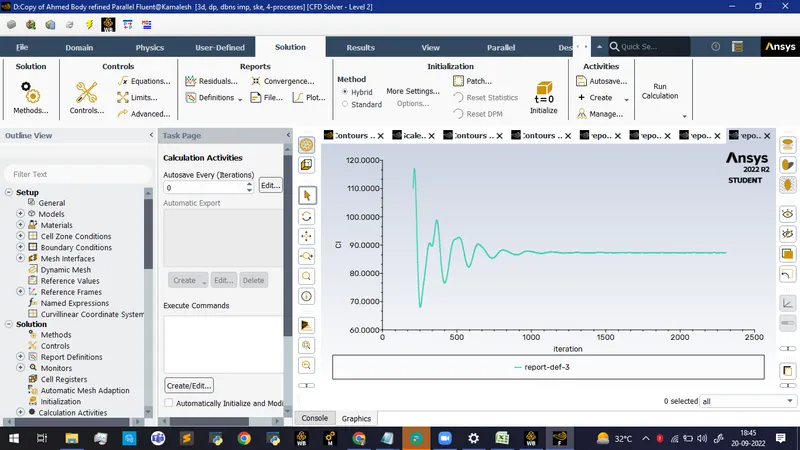
Coefficient of lift and drag plots
Turbulence model: k−ω SST.
The multizone was used for the second area. The number of element size for the outer enclosure is taken as 9090 mm whereas the element size for the inner closure is taken as 4545 mmmm. Face sizing was implemented for the pillars of Ahmed's body ( 5mm).
Inflation layer
First layer thickness: 33mm
Number of layers: 1010
Last layer thickness: 15.479315.mm
Number of elements: 253152253152
The value of y+ is around 207.
Residual plot
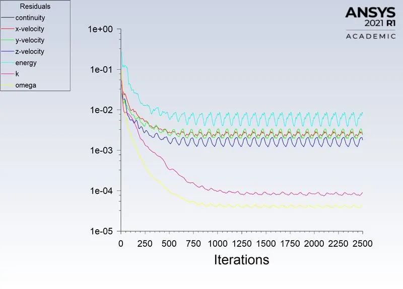
After 1600 iterations the same repeating trends are observed.
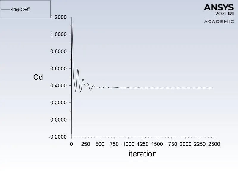
Drag coefficient
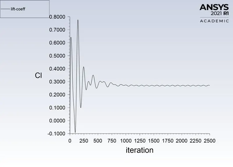
Lift coefficient
Velocity contour
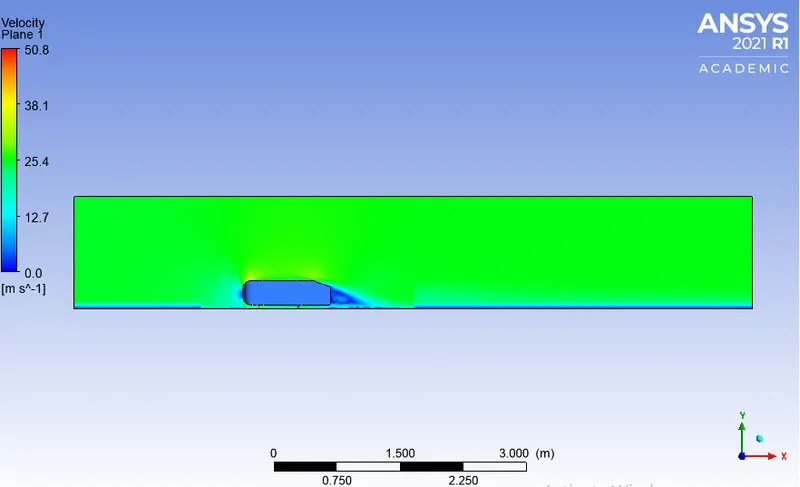
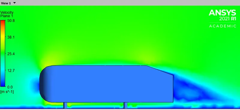
Wake region
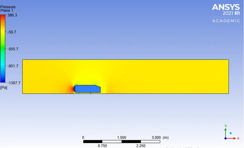
Pressure contour
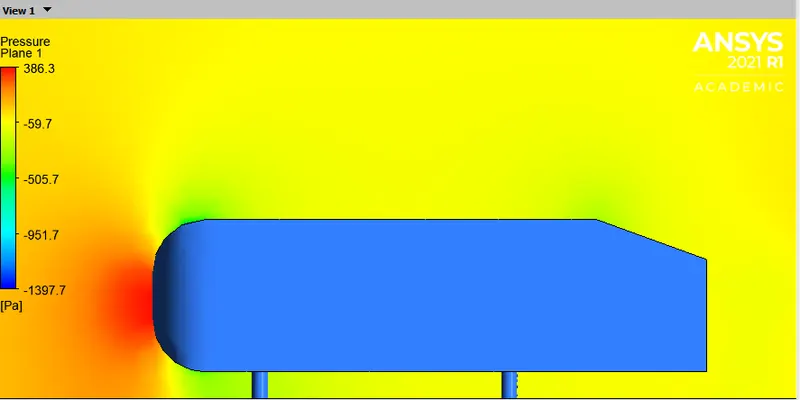
Wake region
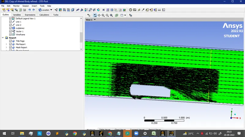
Vector plot showing the wake region
| Drag coefficient | 0.3512 |
| Lift coefficient | 0.2889 |
Case 2(c): Third refinement
Turbulence model: k−ωk-ω SSTSST.
Element size in the first enclosure: 80mm80mm
Element size in the second enclosure: 40mm40mm
Element size of the bottom leg of Ahmed body: 5mm5mm
Number of inflation layer: 1010
First layer thickness: 0.15mm0.15mm
Last layer thickness: 0.77mm0.77mm
Number of elements: 348448348448
Y+ : 1010
Residual plot
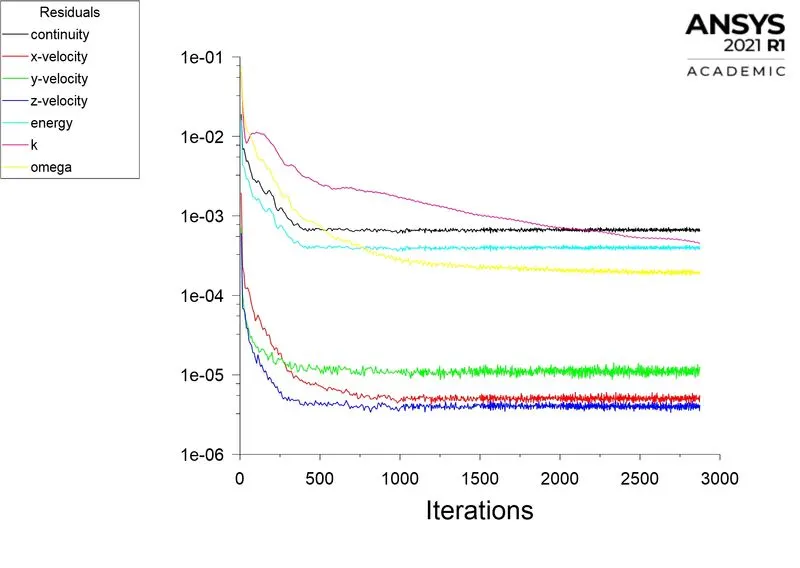
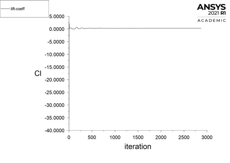
After 1200 iteration the repeating trends are observed.
Drag coefficient plot
Lift coefficient plot
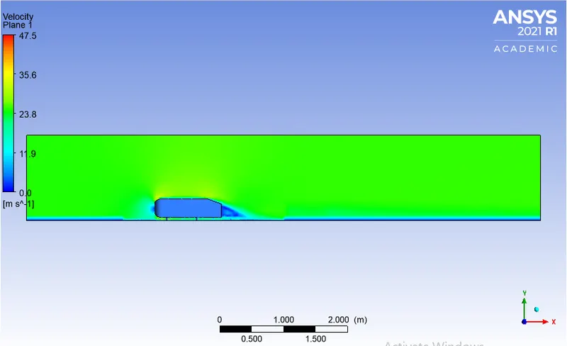
Wake region
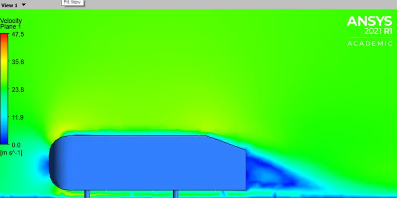
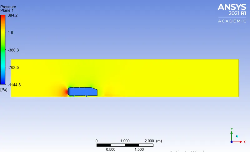
Pressure contour
Wake region
Vector plot near the wake region
| Drag coefficient | 0.3498 |
| Lift coefficient | 0.2884 |
Demonstration of grid independence test
Comparison of all cases
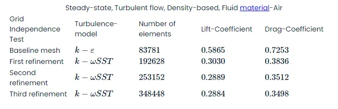
It can be inferred that the imitation of the experimental result is obtained during the second refinement. Thus the grid independence test saves a lot of computational time and convergence can be achieved by using smaller cell sizes for calculation.
Conclusion
- It can be inferred that the grid independence test is performed to know the smaller cell size for convergence.
- Apart from mesh refinement, convergence depends on the Y+ value, inflation layer, it is advisable to use k−ωSST as the turbulence value because it calculates the values well near the wall.
- As the setup is refined drag coefficient, lift coefficient decreases.
- Y+ plays an important role in determining the value of drag.
- The negative pressure in the wake region is primarily because there is no flow in that region. This can be further attributed to various factors such as separation and recirculation which is evident from the vector plot near the wake region.
- The point of separation occurs at the rear end of the vehicle, the separation occurs beyond this point where it can be observed that the flow recirculates and attaches it to the boundary layer.