Week 3 - External flow simulation over an Ahmed body.
Aim : To run External flow simulation over an Ahmed body, Describe Ahmed's body and its importance,Explain the reason for the negative pressure in the wake region,and Explain the significance of the point of separation.
Objective : The objective of this project is to determine the aerodynamic forces on the Ahmed body such as drag and lift coefficient and to perform the grid independence test.
Expected results :
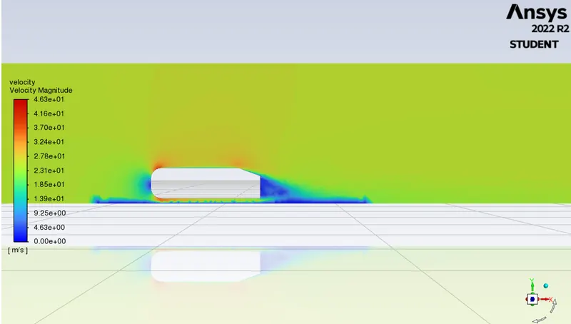
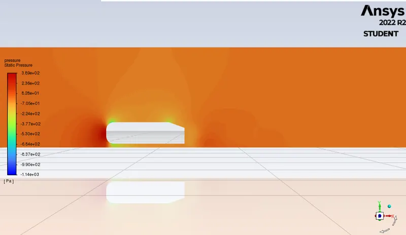
- Velocity and pressure contours.
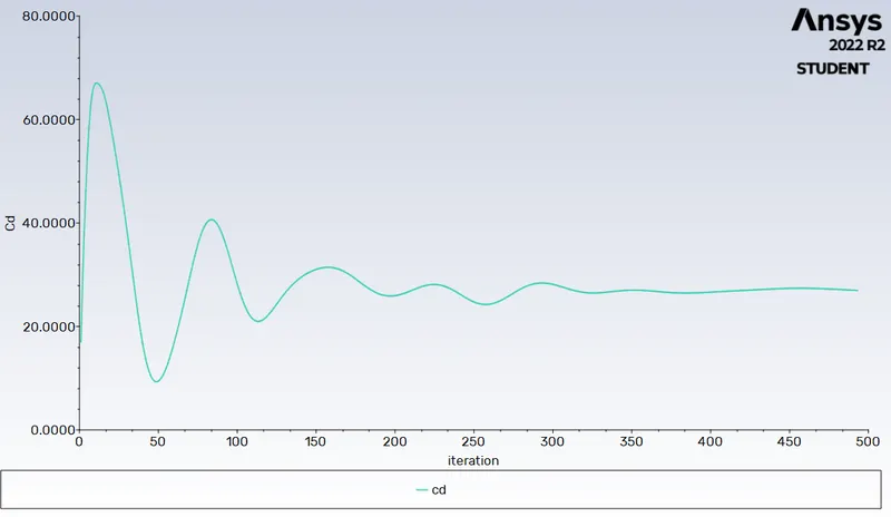
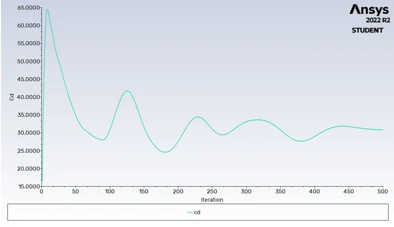
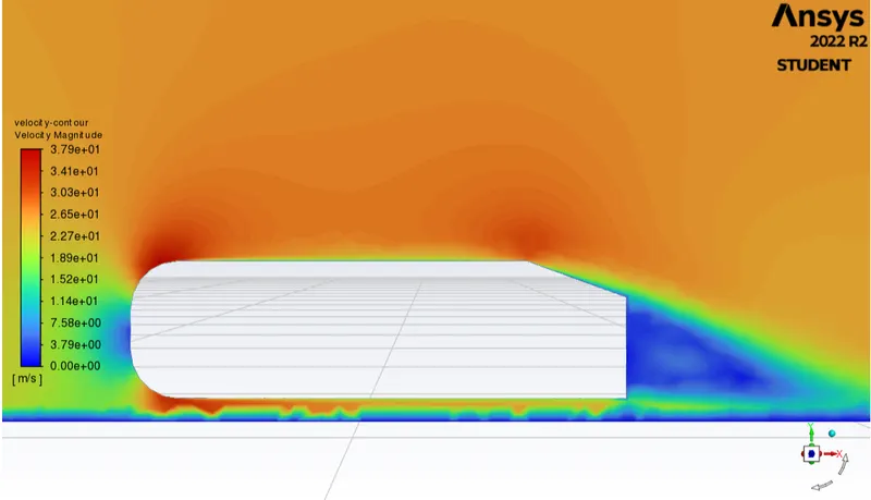
- The drag coefficient plot for a refined case. ( For a velocity of 25m/sec, the drag coefficient should be around 0.33).
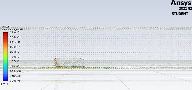
- The vector plot clearly showing the wake region.
- Perform the grid independence test and provide the values of drag and lift with each case.
Introduction :
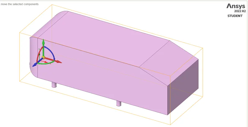
The Ahmed body is simplified car body used in automotive field to study the impact of the flow pattern on the drag. The external aerodynamics of the car defines many major traits of an automobile like stability, comfort and fuel consumption at high speeds. The flow around the vehicle is characterized by high turbulent and three dimensional flow separations as well as there is a growing need for more insight into the physical features of these dynamical flows. The Ahmed Body is a simplified car, used in automotive field to investigate the flow analysis and find the wake flow around the body. Ahmed body is made up of round front part, a moveable z slant plane in the rear of the body to study the detachment phenomena at different angles, and a rectangular box which link the front part and the rear slant plane. The principal objective to study such a simplified car body is to tackle the flow processes involved in drag production. Through perceiving the mechanisms involved in creating drag one can be able to design a car to minimize drag and therefore reducing fuel consumption and maximize vehicle
performance.
Ahmed body :
The Ahmed body has the form of a highly simplified car, consisting of a blunt nose with rounded edges fixed onto a box-like middle section and a rear end that has an upper slanted surface, the angle of which can be varied. The model is supported on circular-sectioned legs or stilts, rather than wheels. Despite neglecting a number of features of a real car (rotating wheels, rough underside, surface projections, etc.) the Ahmed body generates the essential features of flow around a car, namely: flow impingement and displacement around the nose, relatively uniform flow around the middle and flow separation and wake generation at the rear.
Besides the analyses of the velocity field, the Ahmed Body is also used for drag force and lift force analyses and rolling, pitching and yawing moments. The slant angle on the back allows studying the separation region and its influence on the velocity profile and forces.
procedure :
- Import the geometry.
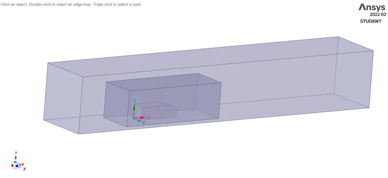
- Create the domain using the enclosure tool. Make sure you uncheck symmetry option for better control over the domain.
- Select the planes option located in the design tab and select the coordinate axis in the GUI to create all the three planes.
- Over to split body tool and select the plane running along the logitudional direction and cut the domain exactly into two halfs.
- We want to simulate external flow dynamics, so, we will make sure that we avoid meshing inside the Ahmed body. In order to do that, select 'suppress for physics' option for solid Ahmed body by right clicking on it.
- Spaceclaim will create a void representing the Ahmed body.
- Creat the enclosers to the ahmed body.
Case 1 :
Meshing :
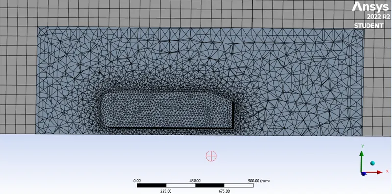
- Take the mesh element size as 100
- Body sizing as 50
- Face sizing as 30
Setting up physics :
- Conduct a steady state simulation.
- Go to physics and select viscous and select K-EPSILON.
- select the material as air.
- Select boundaries and give the inlet value as 25m/s.
- Go to solutions click on defenations and open force report. In that we can find drag and lift. Then creat drag and lift in report definations.
- Go to results and open contour and creat velocity and pressure contours.
- And creat a plane in xy direction.
- Then go to the solution and do hybrid initialize.
- finally calculate the results.
Results :
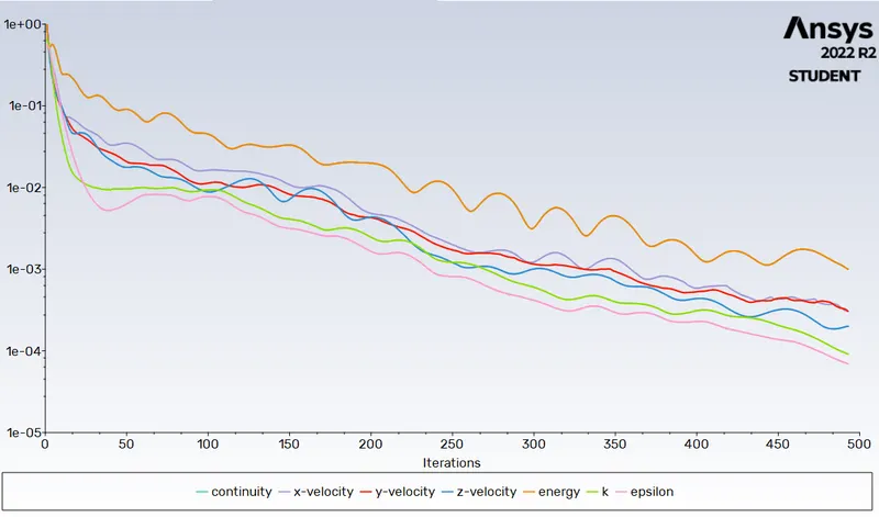
Residual plot :
Coefficient of drag :
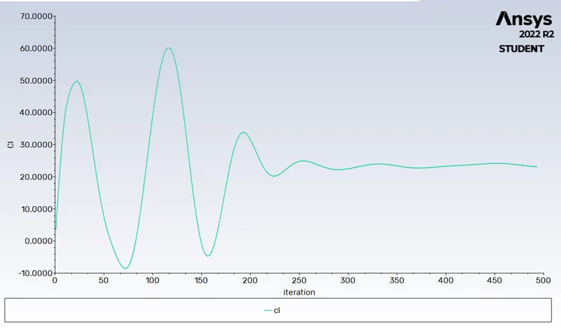
Coefficient of lift :
Velocity contour :
Pressure contour :
Vector plot :
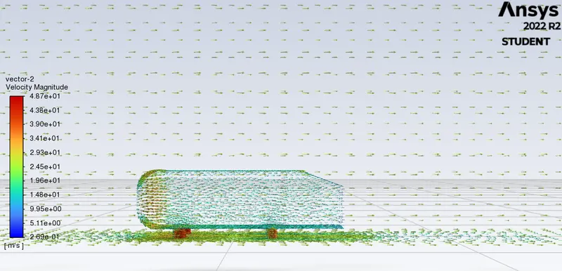
Cd = 0.4164
Cl = 0.2752
Case 2 :
Meshing :
- Take the mesh element size as 70
- Body sizing as 40
- Face sizing as 15
Setting up physics :
- Conduct a steady state simulation.
- Go to physics and select viscous and select K-EPSILON.
- select the material as air.
- Select boundaries and give the inlet value as 25m/s.
- Go to solutions click on defenations and open force report. In that we can find drag and lift. Then creat drag and lift in report definations.
- Go to results and open contour and creat velocity and pressure contours.
- And creat a plane in xy direction.
- Then go to the solution and do hybrid initialize.
- finally calculate the results.
Results :
Residual plot :
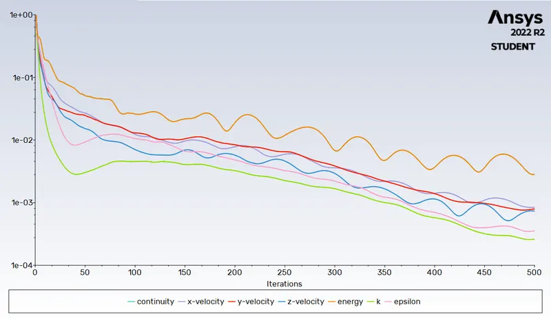
Coefficient of drag :
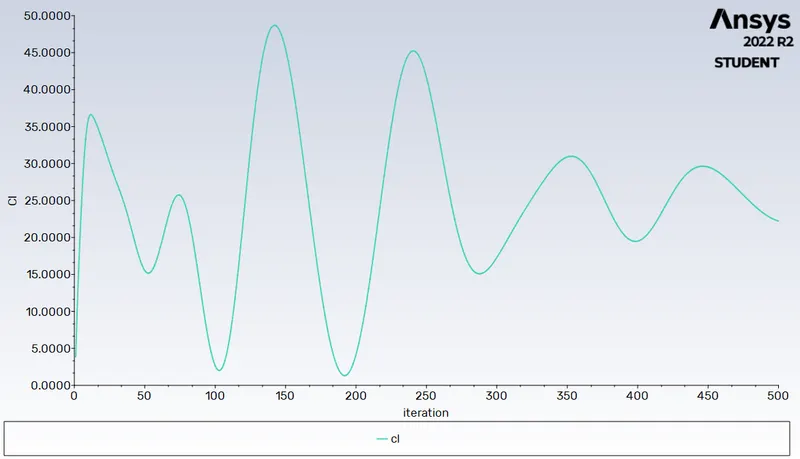
Coefficient of lift :
Velocity contour :
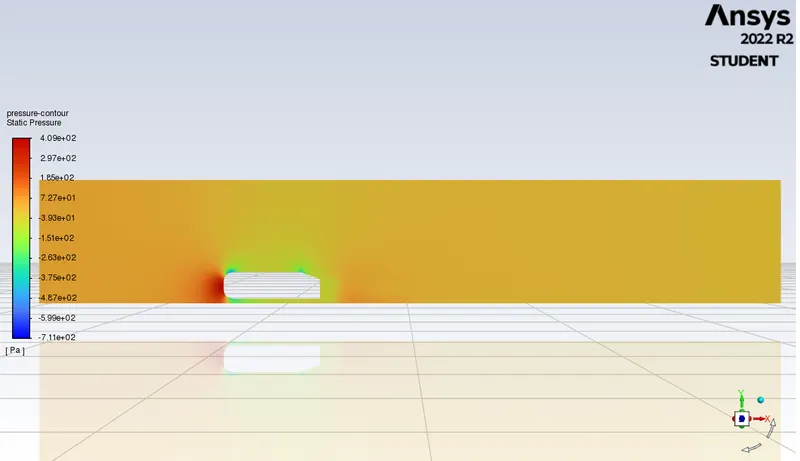
Pressure contour :
Vector plot :
Cd = 0.3502
Cl = 0.2981
Negative pressure gradient :
When fluid velocity increases, the pressure decrease. The wake region is formed due to adverse pressure in the rear end causes the boundary layer to separate out from the body. The wall shear stress and velocity becomes zero and wake formation starts. These wakes are nothing but small vortices that create negative pressure. These create circulation of velocity and induces drag forces.
Point of sapetarion :
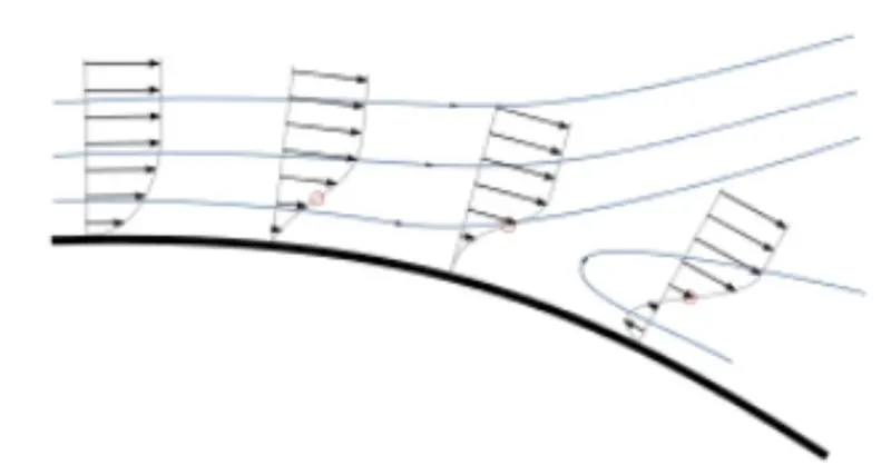
Separation occurs due to an adverse pressure gradient encountered as the flow expands, causing an extended region of separated flow. The part of the flow that separates the recirculating flow and the flow through the central region is called the dividing streamline. The point where the dividing streamline attaches to the wall again is called the reattachment point. As the flow goes farther downstream it eventually achieves an equilibrium state and has no reverse flow.When the boundary layer separates, its remnants form a shear layer and the presence of a separated flow region between the shear layer and surface modifies the outside potential flow and pressure field. In the case of airfoils, the pressure field modification results in an increase in pressure drag.
Conclusion :
- The grid independence test is carried out to demonstrate the variation of the result with respect to the accuracy of the mesh. Good quality mesh is needed for achieving accurate results.
- The inflation layer provided is an added advantage to capture the flow near the Ahmed body.
- The cause of flow separation in the fluid flow is because of the negative pressure generated in the boundary layer of flow near the wall of the body and the negative wake region is generated due to the pressure difference between a low stream and high stream flow also due to flow separations.