Week 3 - External flow simulation over an Ahmed body.
Aim: External flow simulation over an Ahmed body.
Objectives:
As the body is perfectly symmetric, we can run the simulation by considering the only half body. This is the best practice where you can save on the number of cells and get the results faster as well.
The geometry which is provided with the challenge needs a modification which you should be able to do at this stage of a course. You need to use the 'split body' command in SpaceClaim to perform the operation and then you can use the symmetry boundary condition in fluent to perform the simulation.
Run the simulation for the velocity of 25 m/sec with the default air properties in fluent.
Q1. Describe Ahmed's body and its importance.
Q2. Explain the reason for the negative pressure in the wake region.
Q3. Explain the significance of the point of separation.
Expected Results:
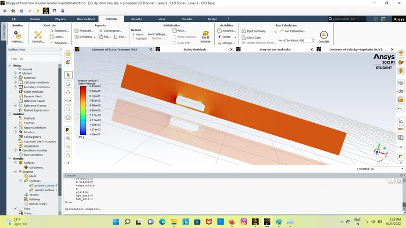
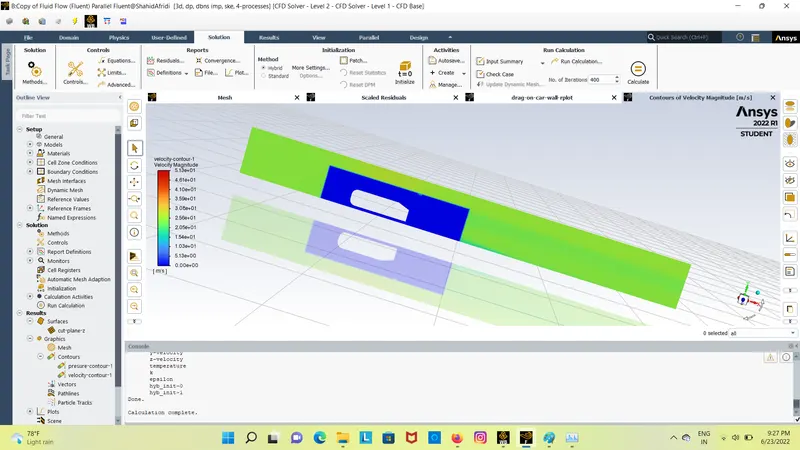
1. Velocity and pressure contours.
2. The drag coefficient plot for a refined case. ( For velocity of 25m/sec, the drag coefficient should be around 0.33).
3. The vector plot clearly showing the wake region.
4. Perform the grid independency test and provide the values of drag and lift with each case.
Describe Ahmed's body and its importance.
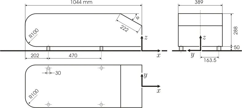
The Ahmed body was described originally by S. R. Ahmed in 1984 [1]. Three main features were seen in the wake:
1. The A recirculation region that is formed as the flow separates at the top of the vertical back surface of the model
2. The B recirculation region that is formed due to the separation at the base of the model.
3. The c-pillar vortices that form as the vorticity in the side boundary layers roll up over the slant edges.
The wake was shown to be highly dependent on slant angle. For slant angles less than 12°, the flow remains attached over the the slant. The flow is essentially two-dimensional and has low drag. Between 12° and 30° the flow becomes much more three-dimensional as the c-pillar vortices form. These reach maximum strength at 30°. The drag increases significantly as the low pressure cores act on the rear surfaces. Past 30° the flow separates fully off the slant. This results in a sudden decrease in drag and weaker c-pillar vortices.
Effect of Aspect Ratio: Venning et al [7] showed that the aspect ratio of the rear slant had a significant effect on the wake. The wider bodies ceased to reattach at slant angles of 25°, suggesting that the critical angle lowers as aspect ratio increases. They also provide vortex core location from experimental data that can be used for validation [8].
Description of the test case: The Ahmed body (Fig. 1) was first defined and its characteristics described in the experimental work of Ahmed [1]. Two configurations with slant angles of 25°and 35°are considered as a test case. For this configurations detailed LDA Measurements have been performed by Becker, Lienhart and Stoots [2,3] in the LSTM low-speed wind-tunnel with a cross-section of 1.87x1.4 m2 (width x height) with a bulk velocity of 40 m/s. The test-section of the wind-tunnel was 3/4 open (only ground plate present). The distance between the body and the plate representing the ground is 50 mm. In the experiment perform by the Ahmed [1], flow velocity was taken 60 m/s, Reynolds number was 4.29 million based on model length.
refrence:https://www.cfd-online.com/Wiki/Ahmed_body
Explain the reason for the negative pressure in the wake region.
In the presure secsion we are hetting negative presure becouse of mesh quality and the velocity we are taking in account during the base line simulation in order to get the possitive presure we have to chane the y+ value as well as we have to improve our mesh
Simulation of ahmed body
Steps invalving in simulation
- geometry
- meshing
- setup
- solution
- result
initial stups
- inlet velocity: 25m/s.
1) geometry: we have to import the geometry in space clime
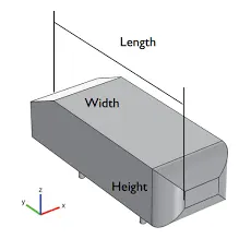
- after that we have to creat the rectangular box arround it as shown below
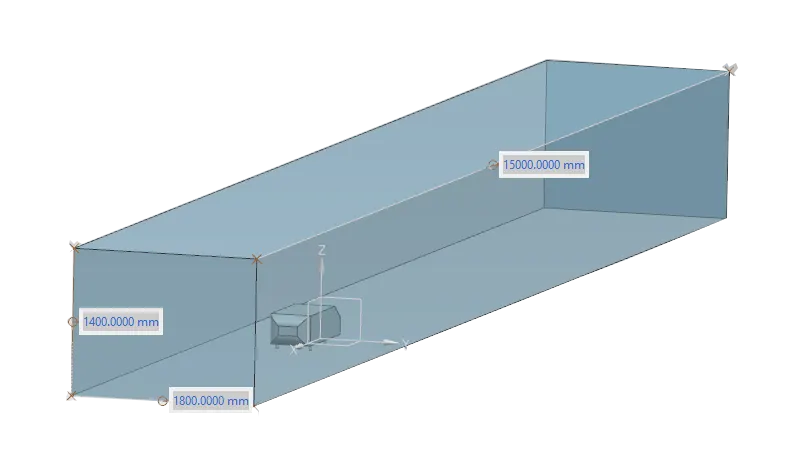
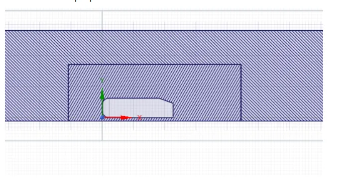
- after that As the body is perfectly symmetric, we can run the simulation by considering the only half body
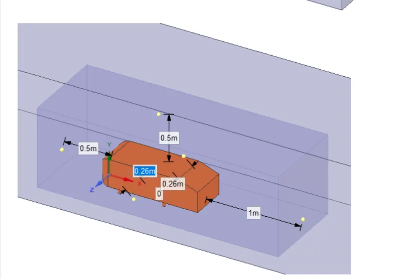
- After creating the both enclosure we have cheak the interference between the layers, in prepaire we have to use the interference command and remove the interference between the two layer.
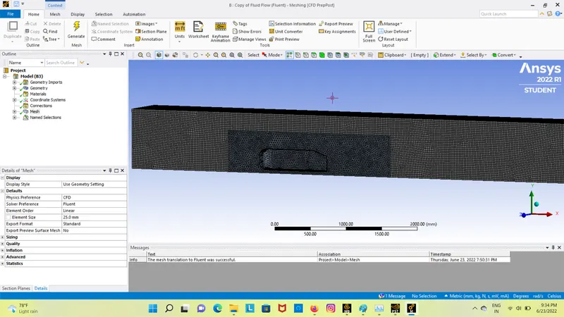
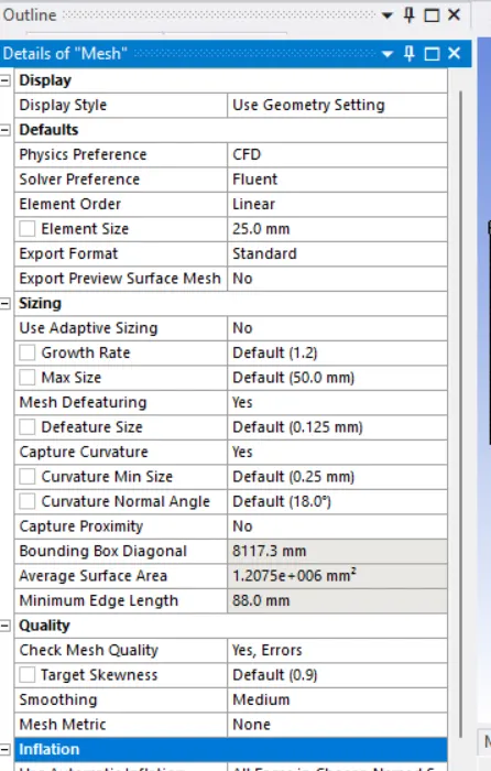
2) meshing: after creating the geometry we have to import in meshing and then we have to create the mesh arround both facesess
outputs:
Presure:
velocity:
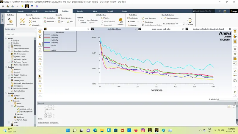
Residual:
drag:
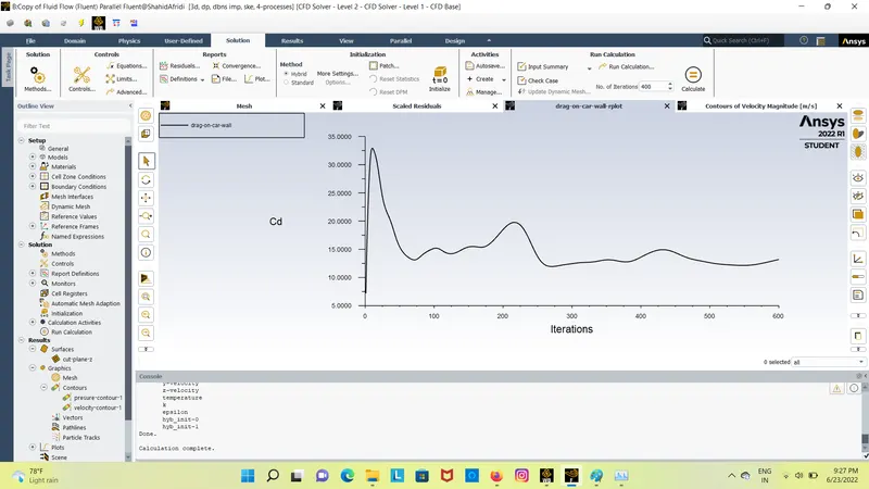
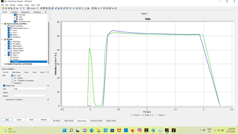
Chart: