Week 3 - External flow simulation over an Ahmed body.
Objective :
Simulation of External flow over the Ahmed body is conducted in this challenge. Parameters such as coefficient of lift and drag are estimated and validated. The wake region is investigated. The grid independence test is conducted.
Software used :
Ansys Fluent 2021
Ahmed Body and its Significance :
The Ahmed body is a geometric entity that represents a standard passanger car. The geometery was first proposed by Ahmed and Ramm in 1984 and was extensively used to study the effect of the geometry on the wake region.
Over the years, numerous studies have been conducted on the Ahmed body both computationallyand experimentally using wind tunnels. Since a lot of data is available on the Ahmed body, today the geometry is primarily as a validation tool for CFD codes. The geometry of the Ahmed body
Importance of Ahmed body
The drag force is an important factor considering fuel consumption. As the drag force increase the fuel consumption also increase which in turn becomes expensive for the car owners. As the burning of fossil fuel becomes an issue, the manufactures are pressing the fuel-efficient cars. One of the main factors considering the car is fuel-efficient or not is the car's geometry.
Complex shaped cars are very challenging to model and its difficult to quantify the aerodynamic drag computationally. The Ahmed body is a benchmark model widely used in the automotive industry for validating simulation tools.
Negative Pressure in the wake region
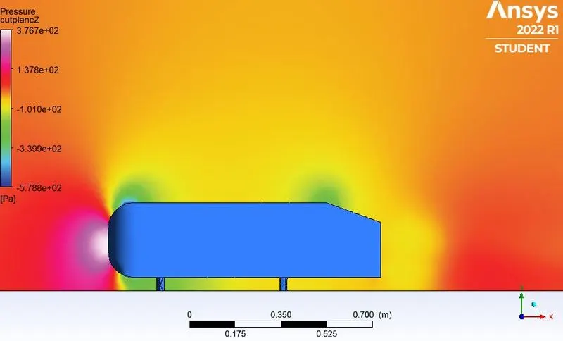
When the air moving over the vehicle is separated at the rear end, it leaves a large low-pressure turbulent region behind the vehicle which is known as the wake. This contributes to the formation of pressure drag which affects the vehicle performance.
When the vehicle is moving at a certain velocity the fluid imports viscous force to the vehicle as long as it is in the viscous sublayer of the boundary. When the fluid reaches the rear end of the vehicle it gets detached from the surface of the body causing negative pressure in the wake region. The movement of the fluid around the vehicle depends on the geometry of the car and the Reynolds number.
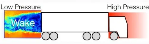
Significance of point of seperation :
The point of seperation will occur when there is a discontinuity in the surface or a region of the nagative pressure gradient ( a sharp end or rear portion of the car)
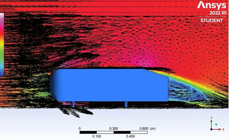
When the flow is attached to the body of the vehicle the viscous force will increase the pressure and a decrease in velocity before the rear end of the vehicle. As soon as the air encounters the sharp turn causing the velocity to decrease resulting in the negative pressure region which is in the wake region. The recirculation region happens beyond the point of separation.
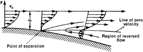
If the rate of change of pressure is large the mixing process will not occcur and the boundary layer flow stops.
The above figure shows that at the point of turning the flow gets seperated from the boundary layer and there is a region of recirculation after which the flow attaches itself to the boundary layer.
In oreder to reduce the seperation of fluid from the boundary layer, it is advisable to have a smooth edge to reduce the effect of drag on the vehicle.
Modelling approach
Baseline simulation approach using k-e model
Ahmed's body is loaded into the Spaceclaim.
A single enclosure is drawn across Ahmed's body.
Now the geometry is loaded for meshing.
A baseline simulatin is set up with the default element size of Ansys.
A named selection is created for the enclosure viz; inlet, oulet, symmetry,walls.
To create the name selection for the car the enclosure faces are hidden and box select is selected from the meshing toolbar.
Ansys Fluent window is opened and the geometry is loaded.
Steady-state, the density-based solver is selected.
References values are updated as per the prescribed conditions.
In the inlet boundary condition, inlet velocity is 25m/s and 300k temperature are set.
Drag-coefficient plot and lift-coefficient plot is created by setting the refrence
Hybrid initialization is selected.
The solution is initialized by hitting t = 0
The cut-plan-z is created alon Ahmed's body.
The velocity contour, pressure contour is created along the cut-plan-z.
The animation video is created for the velocity contour.
The simulation is executed for 1000 iteration.
Simulation with a finer mesh using k-wSST.
The first simulation ran successfully.
The geometry is loaded into the Spaceclaim.
The region of local refinement is created along Ahmed's body.
As the body is perfect symmetric, the simulation is executed by considering the only half body. This is the best practice where we can save on the number of cells and gets the results faster as well.
The geometry is loaded for meshing. The multizone method is selected for the outer enclosure to provide hexahedral mesh which provides accurates results in simulation.
The element size for the first enclosure is will vary as (100mm,90mm,80mm) the element size for the second enclosure will vary as(50mm,45mm,40mm), the element size of the leg of Ahmed's body will be 5mm, the first layer thickness,inflation layer, and the maximum thickness will be varied accordingly to imitate the experimental results.
The rest procedure is the same as above, the necessary contour plot and graphs have been uploaded respectively.
Procedure : -
Change the units mm to meters.
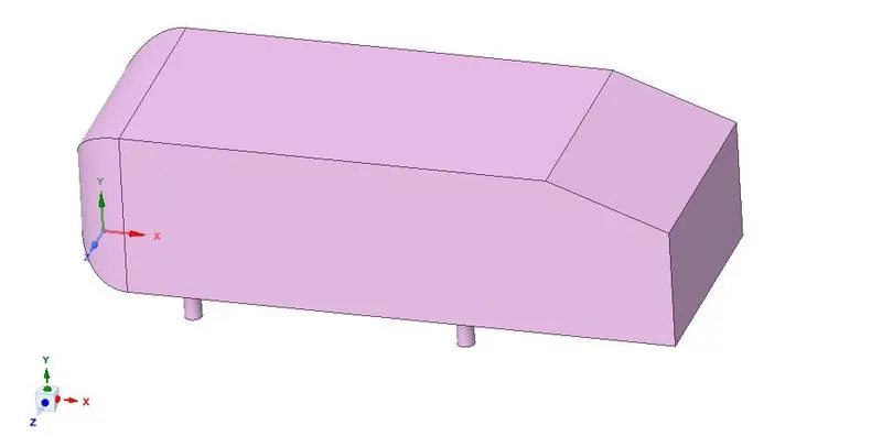
Go to File menu bar ,click on enclosure and click on the Ahmed's body and on the left side of the Spaceclaim uncheck the symmetric dimensions in order to have more control on the body part.
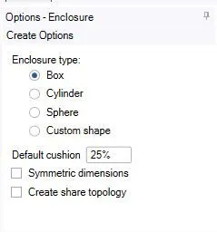
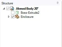
First thing i am going to change the dimensions. Here basically we created two components first one is the actual ahmed body which we origially imported and then enable the enclosure.
Now i m going to design and clicking on the plane tool if i am clicking on origin i was automatically got 3 sets of planes one that has normal along x-axis, one has normal along y-axis and another has normal along z-axis.
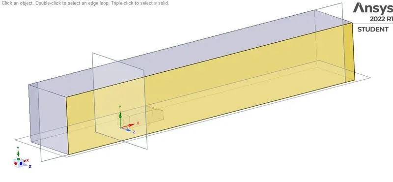

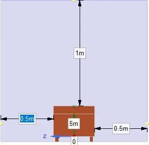
Then i'm going to cut the plan whose normal along y axis and Ahmed's body is automatically is cutin exactly what we need for the simulation.
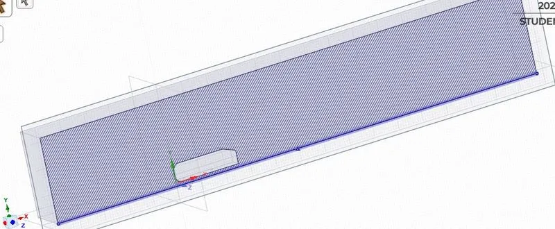
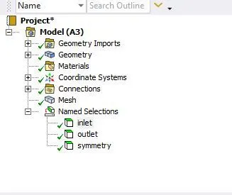
Next i am come back to workbench, open meshing. first of all i doing the face selection tool and hit 'N' shortcut key for giving the names of the faces according to the positions such as inlet, outlet, symmetry.
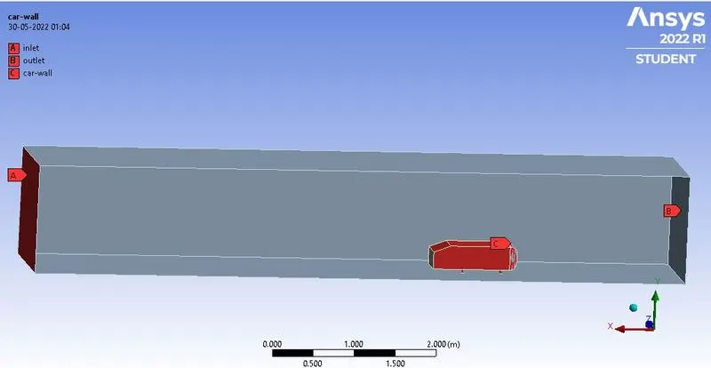
Now, hide the one of the face by pressing f8 key in order to select the Ahmed's body with the help of 'box selection' tool and create a name 'car-wall' by pressing the shortcut key name 'N'
Generate a mesh and cut this meshing part by using 'section plane'.The mesh has been generated but we can also see that the mesh is inside the Ahmed's body now this is not good because having mesh in a region where we don't want to simulate the flow. but we dont any mesh inside body beacause we are going to analysis outside the body in this case. How to fix this , just go back to spaceclaim simply.
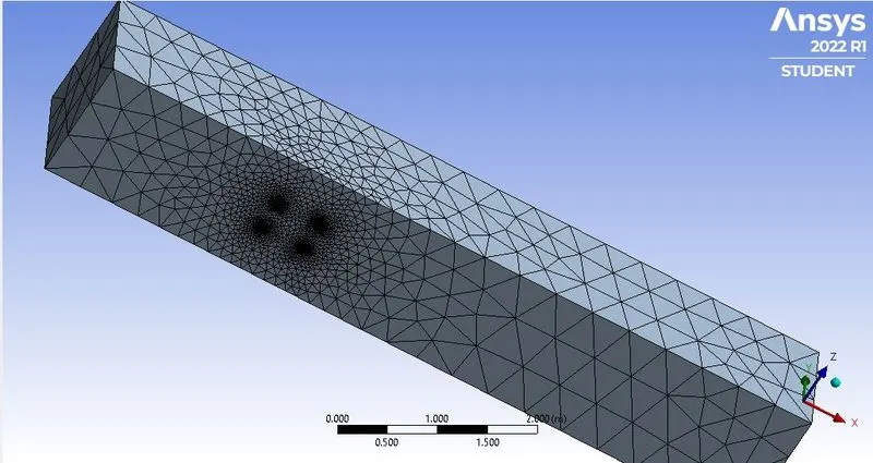
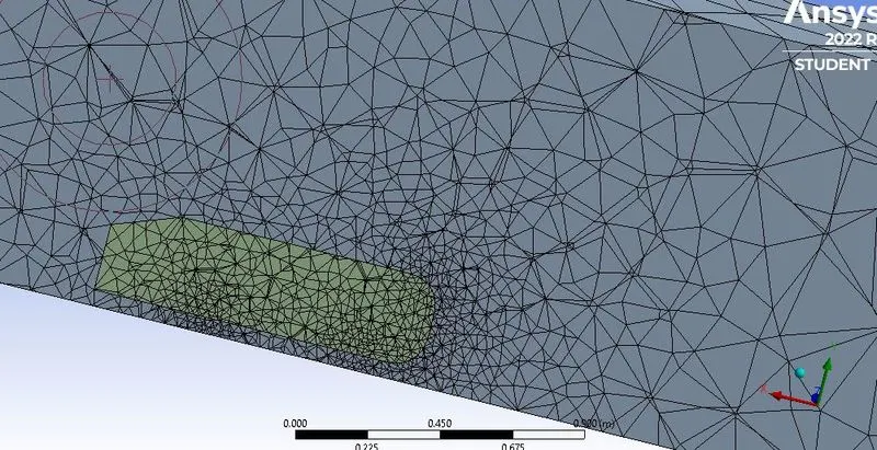
Here in spaceclaim if i can see in the left above corner i have 2 copies of the Ahmefd's body. for first i am going to supress the physics.
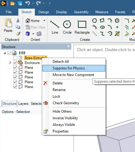
Now comback to meshing again and click on mesh and clear the generated data and generate mesh one more time.
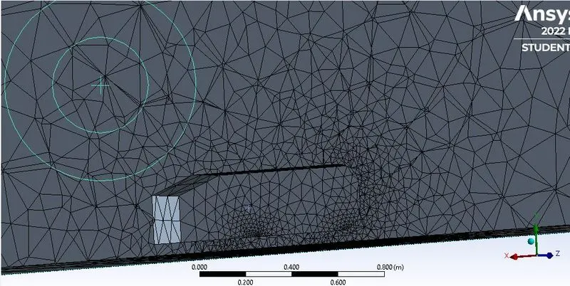
Now i am going to launch 'SETUP' with 4 solver processor. here i am going to check the mesh hence the mesh is OK.
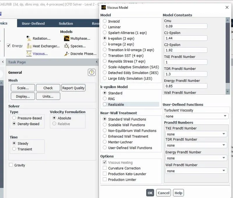
Go to physics and checkout the general parameters and i am using here denisty based solver because i need to take into account compressibility effects.
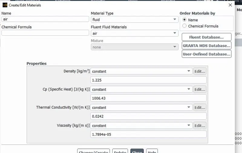
Now i am going to setup the physics and using here k-epsilon model and in this case i am going to turn ON energy equation and for materials the default material is air that what i exactly want.
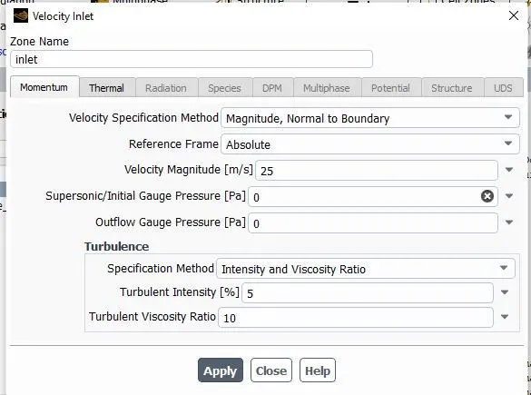
Let's go to boundaries then click on 'inlet' and provide the value of velocity i.e 25m/s and temperature is 300k.
Now this is ready to solving, let's first initialize using Hybrid. when we using Hybrid solver it's basically using a potential flow solver.
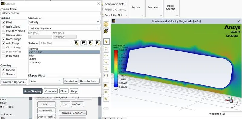
Now go to 'Results' in order to create cut plane in order to see how velocity looks like and this is what we want to monitor as simulation is Done. As we know our flow is going on towards the x directions and we want to create a plan which has normal to the direction of z . So let's go to create a plane and i am going to use point at normal and give the name of the file is 'cut-z-plane' .
Now i am going to 'contour', click on new and rename it as velocity-contour and select contours of velocity.
So as the solution is going to calculated we want to make an animation for the velocity so i am just click on 'solution animation' and save it as a name of velocity-animation.
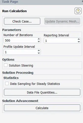
Finally, i am going to running this for 500 iterations and hit calculate.
Next, move to the postprocessinng , now i am going to color the car wall element now here we can see that the pressure at the front of the car.
Now i am going to inserting a plane and calling it as cut-plane-z and i want it to be in the YX plane and click on apply.and we can see here the wake region means the velocity getting lower here and we should have to make vector plot as well.
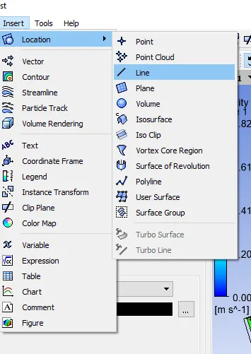
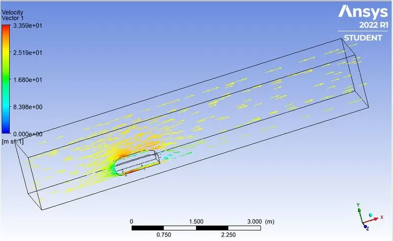
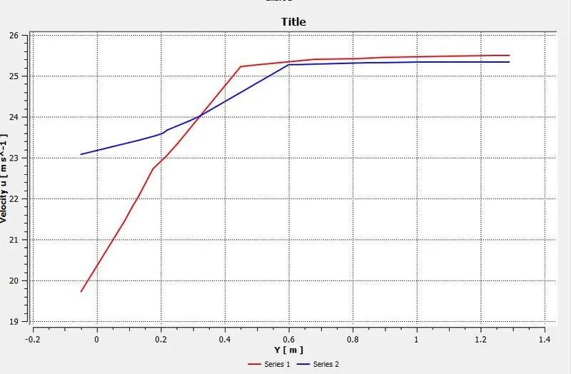
We can see here lines above the Ahmed's body, back of the ahmed's body and top of the ahmed's body and along those line i am measuring the velocity so we will get very nice velocity profile. so how we can do that so, let's disable the vector plot and insert a line.here i am using 'cut' command to cut the domain and get data.
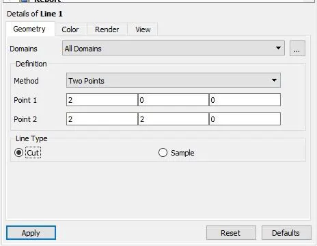
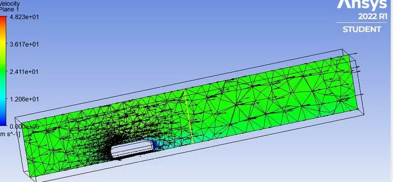
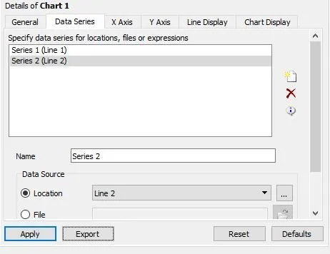
furthermore, I am going to create a chart and let's call it as 'chart1 ' and this is going to be a 'xy-line chart' and in 'x-axis' using variable 'y' and in y-axis using variable name 'velocity x' , the x component of velocity and Also duplicate the line 1 and call it as line 2 and i am changing the co-ordinates to '3' before this i have a coordinate is '2' and here see now 2 line are appeared in the '3d viewer'.
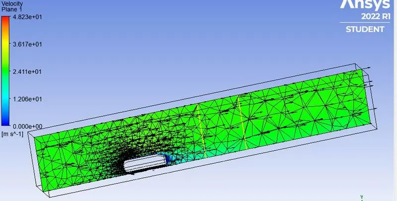
Now i am go back to chart and upload data 2 series in the Data series and it has known to be line 2 and click on ok and we will get a one more line drawn in the plot.
and the nice feature is click on 'Export' in order to save the data.
Refined Case :
In the meshing part as i can see that the meshing are overlapping in the bigger box and in the samll box each other. so for this i was comeback to geometry again.
Here i am get plan tool and pointed out towards the region so when i do that it showing 3 planes, that's what i want and if click on the origin it automatically shwon 3 planes and now make sure that to hit escape to exit the plane tool.
first of click on the plane 1 and hit the croos-section mode, so each section has a particular hatch patern and we can see that the hatch inside our small box having overeloverlapping region which we don't want that.
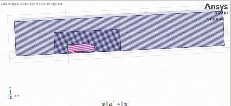
so i will go to prepare and run the ineterference check we can see that huge interference there. now click on OK and its basically solve the problem. so now we can see that there is no overlap.
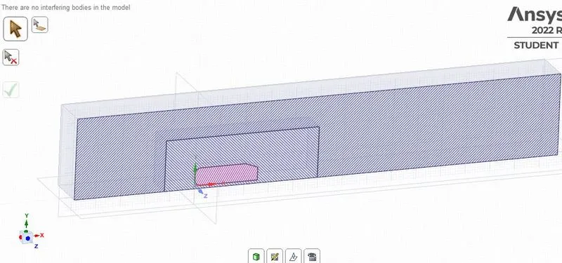
Now exit out the section move and come to 3D mode and hide all of the planes and now i am showing you each of the enclosure.Now after checkout all of the things come to the meshing part again.
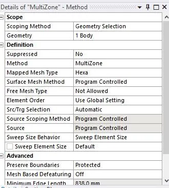
Now generate the mesh,and insert a new method inside the mesh and select the outermost body and hide the section planes. in the geometry section just click apply in order to modifying the meshing method for that particular body and for method i am using 'multizone' and this method goes to trying to convert hexahedral meshing where-ever possible.
Then, for fundamental mesh i am going to do some modification.
Meshing
The meshing involve the following steps
Method
Outside the box, the hexahedral mesh is used. The mesh is the highest quality and gives higher accuracy.
Multizone method : It is used to create hexahedral meshes wherever possible and for other region where different mesh type are used it will connect it properly.
Sizing: It is defined as increasing the number of elements by decreasing the element size. The element size of the second closure is
Element size for the first enclosure : 100mm
Maximum size for the first enclosure : 100mm
Element size for the first enclosure : 50mm
Maximum size for the first enclosure : 50mm
Number of elements : 126315
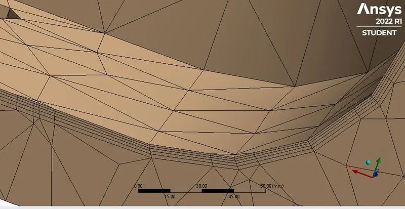
Inflation Layer : It is the process of adding layers to the boundary to cover the boundary layer thickness fully.
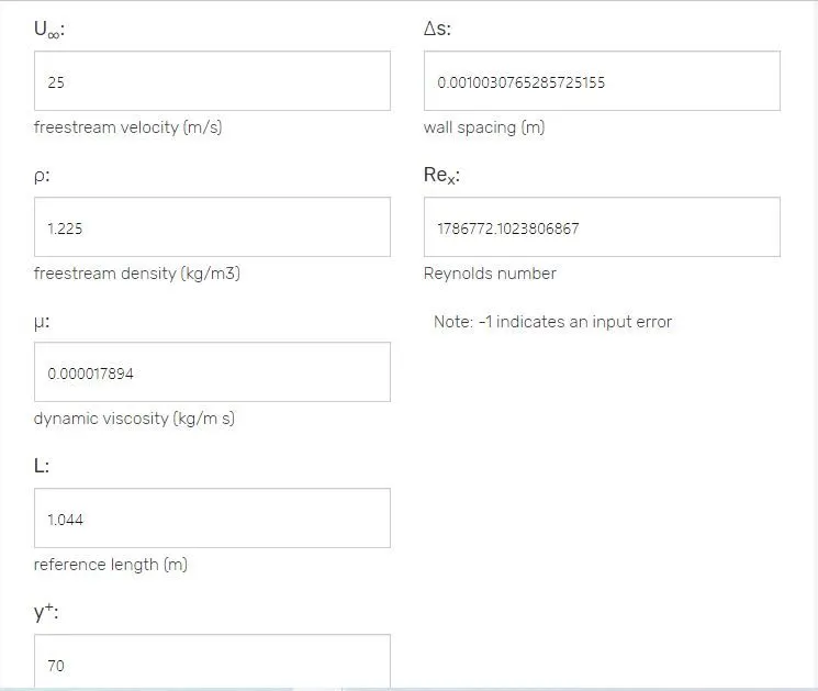
The first cell height predicted value is 1mm
Y + value : 70
First layer height solving technique
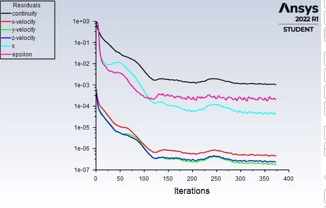
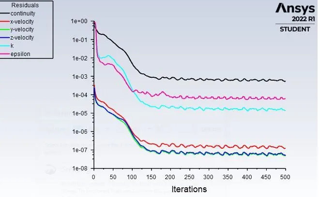
Residual Plot
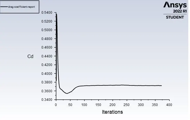
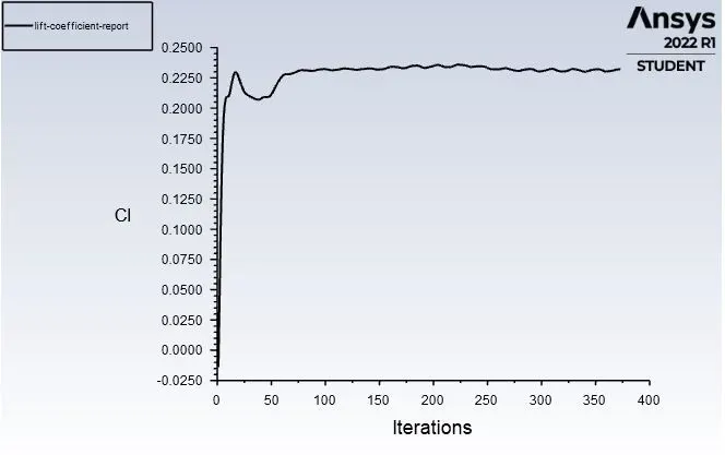
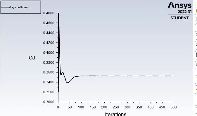
Drag and lift coefficient
Velocity contour
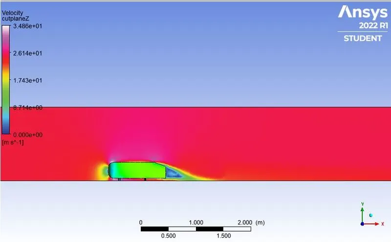
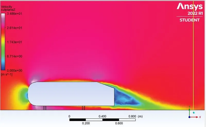
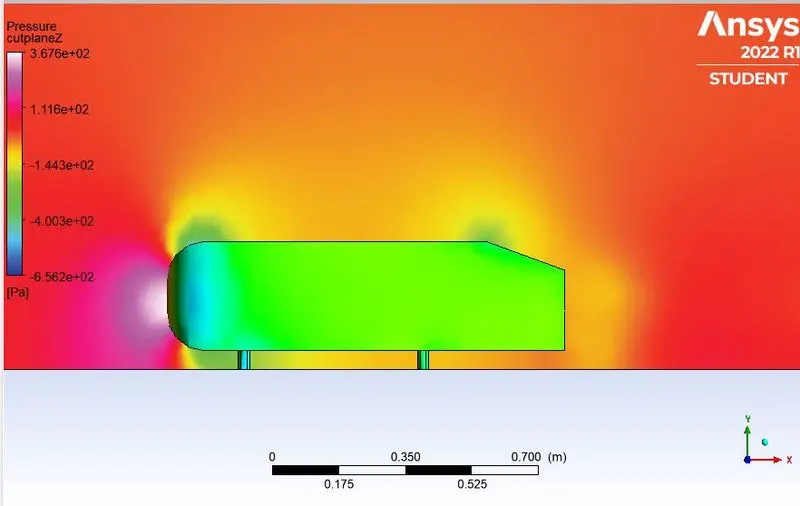
wake region
Pressure contour
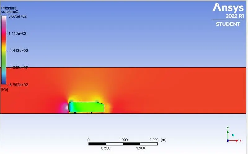
wake region
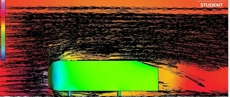
Vector plot showing the wake region
Case 2(b) : Second refinement
Turbulence model : k-epsilon
The multizone was used for the second area. The number of element size for the outer enclosure is taken as 50 mm whereas the element size for the inner closure is taken as 35 mm. Face sizing was implemented for the pillars of Ahmed's body (1mm)
Inflation layer
First layer thickness : 1mm
Number of layers : 5
Number of elements : 471917
y+ value : 90
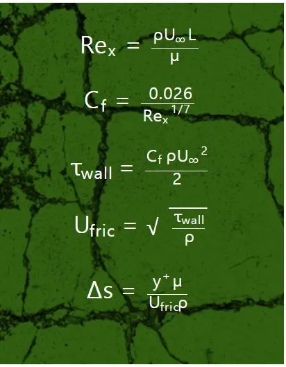
How to find wall spacing /first layer height
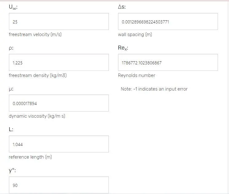
How this actually work behind the screen
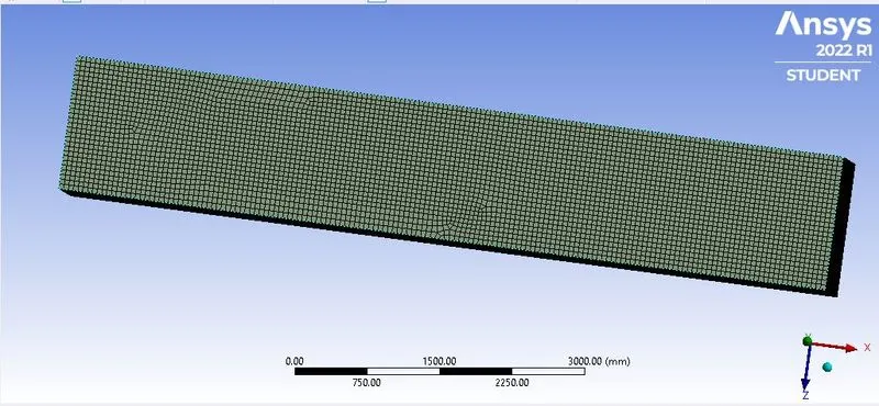
Residual plot
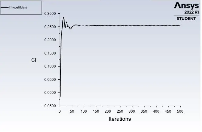
Drag and lift coefficient
Vector contour
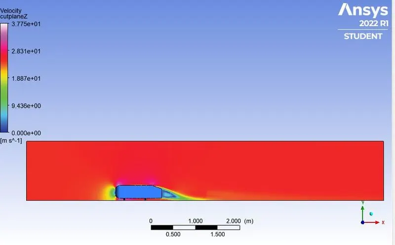
wake region
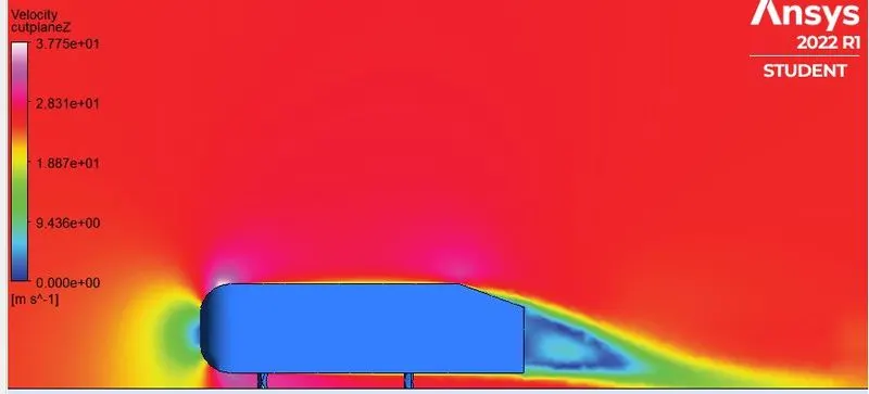
Pressure region
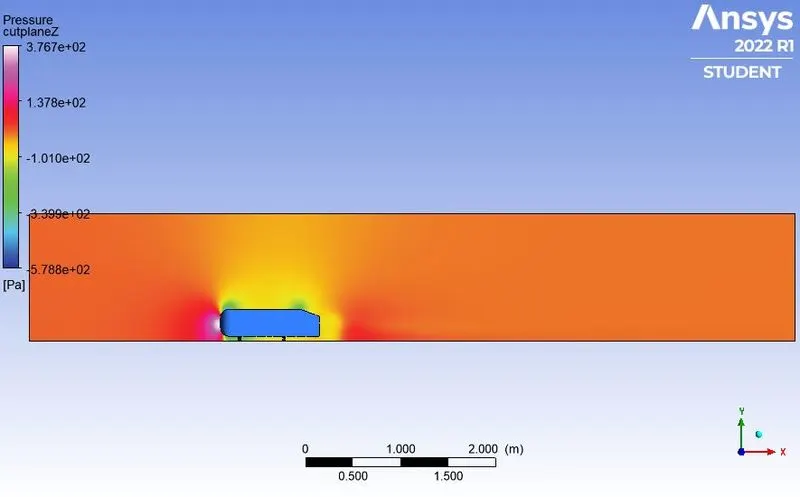
wake region
Vector plot near the wake region
Grid independency test
| Test | Number of Elements | Cd | Cl |
| Baseline mesh | 84073 | 0.36659 | 0.186717 |
| First refinement test | 126315 | 0.37214 | 0.2321038 |
| Second refinemnet test | 471917 | 0.352418 | 0.25338771 |
Here i am used k-kepislon model for three of the method because as we know that from
the value of 0-10 Y+ is for k-omega model
and
for 10-30 this is the dumbest region we could't perform anything here
between 30-300 k-epislon (Releasiable)
method going to be used.
it can be infered that the imitation of the experimental results is obtained during the second refinement. Thus the grid independence test saves a lot of computational
time and convergence can be achieved by using smaller cell sizes for calculation.
Conclusion :
- It can be infered that the grid independence test is performed to know the smaller cell size for convergence.
- Apart from mesh refinement, convergence depends on the Y+ value, inflation layer.
- As the setup is refined drag & lift coefficient decreases.
- Y+ plays an important role in determining the value of drag.
- The nagative pressure in the wake region is primarily because there is no flow in that region. This can be further attributed to various factors such as seperation and recirculation which is evident from the vector plot near the wake region.
- The point of seperation occurs at the rear end of the vehicle, the seperation occurs beyond this point. where it can be observed that the recirculates and attaches it to the boundary layer.
Refernces research paper
https://www.researchgate.net/publication/330383775_Experiments_and_numerical_simulations_on_the_aerodynamics_of_the_Ahmed_body