Week 3 - External flow simulation over an Ahmed body.
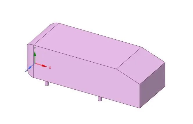
Ahmed body: The Ahmed body was first created by S.R. Ahmed. It is an important benchmark for aerodynamic
simulation tools. It has a length of 1.044 meters, the height of 0.288 meters and the width of 0.389 meters. It also has a 50 millimeter cylindrical legs attached to the bottom of the body and the rear surface which has a slant that falls of at 35 degrees.
The flow for the model is turbulent which is based on velocity and body.
Importance of Ahmed body:-
The drag force is an important factor considering fuel consumption. As the drag force increases the fuel
consumption also increases which in turn becomes expensive for the car owners. As the burning of fossil fuels becomes an issue the manufacturers are pressing for fuel efficient cars. One of the main factors considering the car is fuel-efficient or not is the cars geometry. Complex shaped cars are very challenging to model and its difficult to quantify the aerodynamic drag computationally. The Ahmed body is a benchmark model widely used in the automotive industry for validating
simulation tools.
Negative pressure in the wake region:-
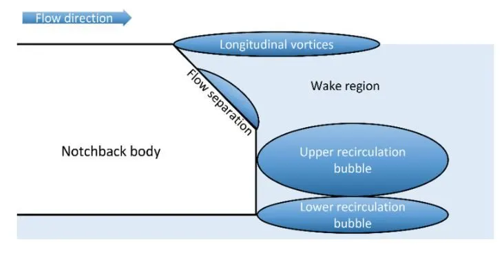
When the air moving over the vehicle is separated at the rear end, it leaves a large low-pressure turbulent region behind the vehicle which is known as the wake. This contributes to the formation of pressure drag which affects the vehicle performance.
When the vehicle is moving at a certain velocity the fluid imparts viscous force to the vehicle as long as it is in the viscous sublayer of the boundary. When the fluid reaches the rear end of the vehicle it gets detached from the surface of the body causing negative pressure in the wake region. The movement of the fluid around the vehicles depends on the geometry of the car and the Reynolds number.
Significance of point of separation:-
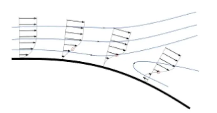
The point of separation will occur when there is a discontinuity in the surface or a region of the negative pressure gradient (a sharp end or rear portion of the car). When the flow is attached to the body of the vehicle the viscous force will increase which will increase the pressure and a decrease in velocity before the rear end of the vehicle. As soon as the air encounters the sharp turn causing
the velocity to decrease resulting in the negative pressure region which is in the wake region. The recirculation region happens beyond the point of separation.
If the rate of change of pressure is large the mixing process will not occur and the boundary layer flow stops. The above figure shows that at the point of turning the flow gets separated from the boundary layer and there is a region of recirculation after which the flow attaches itself to the boundary layer. In order to reduce the separation of fluid from the boundary layer, it is advisable to have a smooth edge to reduce the effect of drag on the vehicle.
CASE Setup :-
CAD clean up/Pre-process-SpaceClaim - Import the Ahmed body in SpaceClaim. And then make an enclosure around the body by using suitable data.
Meshing :- Apply boundary names at different faces and generate the mesh by giving the value element size. Apply mesh sizing and proper inflation to capture the data properly.
Setup :- In this section, we set up the simulation. Kε model is applied for simulation. Keep the material properties (density and viscosity) as it is. And then we apply cell zone condition for simulation. we apply different boundary conditions like inlet , outlet boundary conditions. Apply the reference values like area, velocity and lenght. Then we prepare the report definition for Drag coefficient over the Amed body. After this initialize the process. Prepare Contour plots for pressure and velocity. Certain No of iterations are set for simulation.
Solution :- We get the plot of residual, Average vortex velocity magnitude, Lift coefficient, Drag coefficient. And we can see the animations for pressure and velocity contour.
Results :- Post processing is carried in this section in which different contours are obtained to visualize the properties (such as pressure and velocity). Plot the vector plot to see the wake region.
Set up of geometry (For base simulation)
CAD clean up/Pre-process-SpaceClaim - Import the Ahmed body in the SpaceClaim. Area = 0.112032 m^2, lenght = 1.044 m ,
To make an enclosure apply the dimensions of the block shown below.

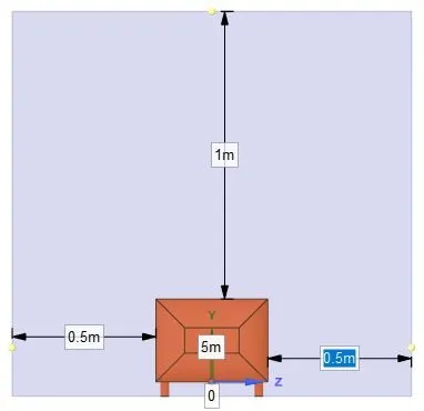
Apply this dimensions and get the enclosed body.
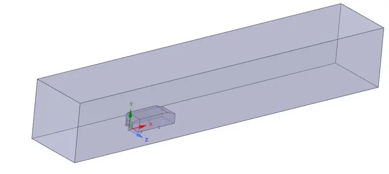
Meshing :- Apply boundary names at different faces like inlet, outlet and symmetry and generate the mesh by using the default value element size provided ny ANSYS.
Element size = 0.4136 m
No of elements = 82814

Setup :- In this section, we set up the simulation. Kε model is applied for base simulation. Keep the material properties (density and viscosity) as it is. And then we apply cell zone condition for simulation. we apply different boundary conditions like inlet , outlet boundary conditions. Apply the reference values like area, velocity and lenght. Then we prepare the report definition for Drag coefficient over the Amed body. After this initialize the process. Certain No of iterations are set for simulation.
Velocity inlet= 25m/s, Area = 0.112032 m^2, lenght = 1.044 m . No of iteration = 500
Solution:-
Residual :-
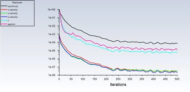
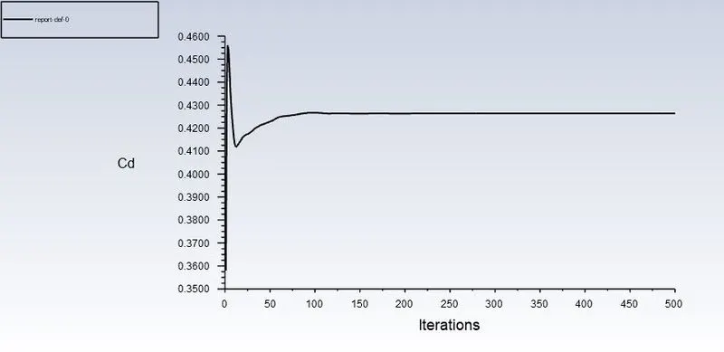
Drag coefficient:- 0.4264
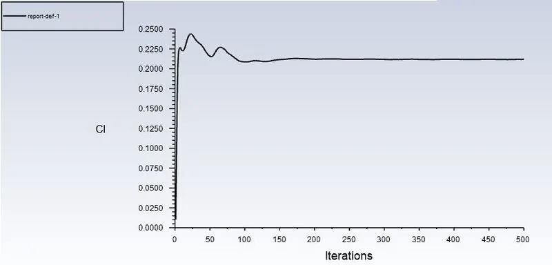
Lift coefficient = 0.2119
Results:-
Velocity contour:-
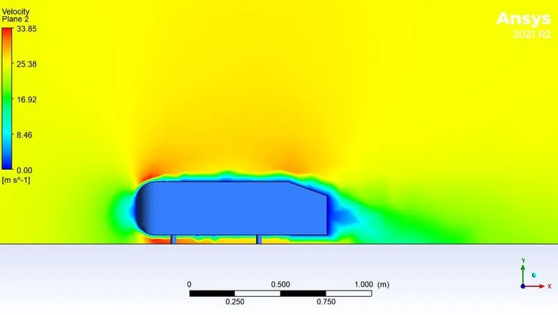
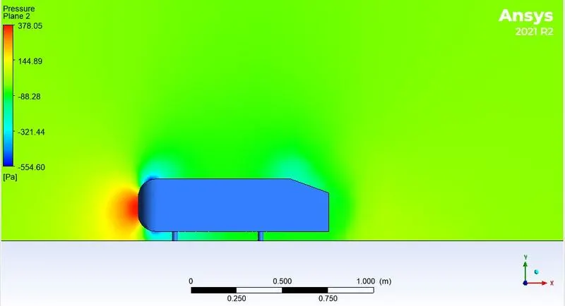
Pressure contour:-
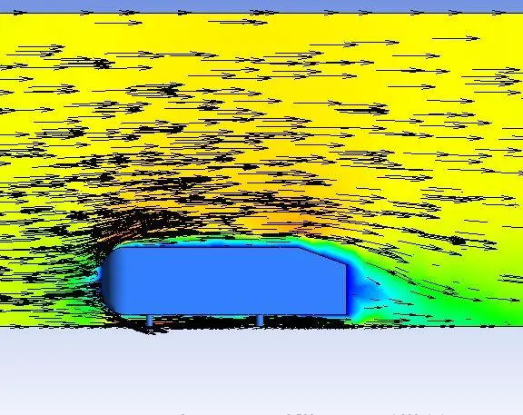
Vector plot :-
Refined case:-
(Here we use Kω model)
CAD clean up/Pre-process-SpaceClaim - Import the Ahmed body in the SpaceClaim. Area = 0.112032 m^2, lenght = 1.044 m ,
To make an enclosure apply the dimensions of the block shown below.
Apply this dimensions and get the enclosed body.
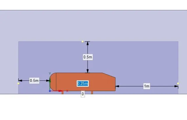
For better result we prepare another enclosure in the existing enclosure.
Here is the dimensions of the enclosure.
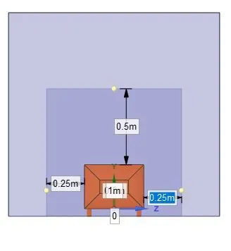
If we proceed from here then we get the overlapping of mesh which can not give accurate answer.
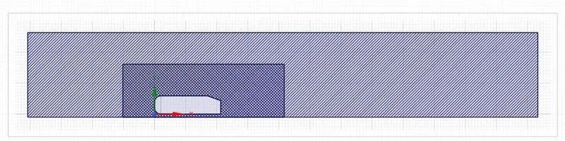
To avoid this we use interference and can check by using plane.
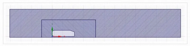
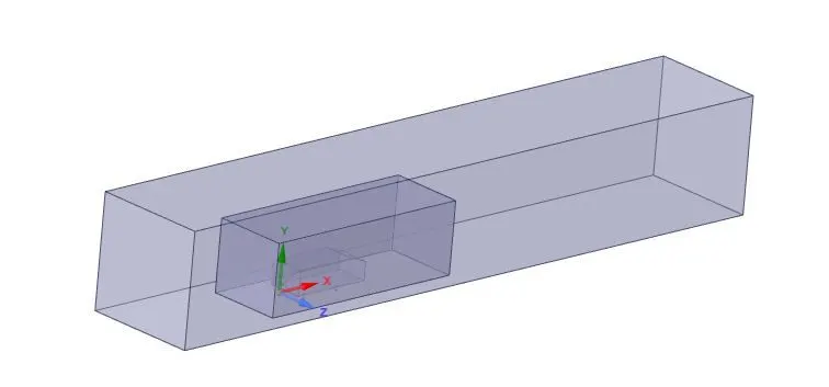
Then the final enclosure looks like shown below.
Meshing :- Apply boundary names at different faces like inlet, outlet and symmetry and generate the mesh of element size = 100 mm
Apply method and select outer enclosure and multizone option to create the mesh shown below.

Apply body sizing on inner enclosure and apply element size of 20 mm. And the apply inflation layer on body of 5 mm of total thickness and 10 layers.
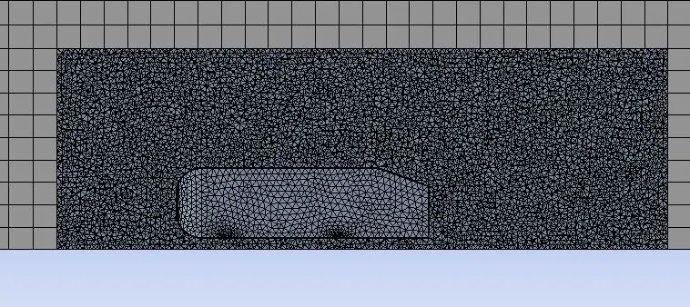
Apply face sizing on 4 base supports of body about 5 mm.
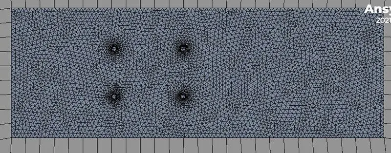
No of elements :- 339802
Setup :-
In this section, we set up the simulation. Kω model is applied . Keep the material properties (density and viscosity) as it is. And then we apply cell zone condition for simulation. we apply different boundary conditions like inlet , outlet boundary conditions. Apply the reference values like area, velocity and lenght. Then we prepare the report definition for Drag coefficient and Lift coefficient over the Amed body. After this initialize the process.Certain No of iterations are set for simulation.
Velocity inlet= 25m/s, Area = 0.112032 m^2, lenght = 1.044 m . No of iteration = 250
Solution:-
Residual :-
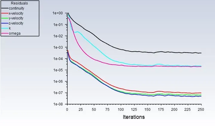
Drag coefficient:- 0.3812
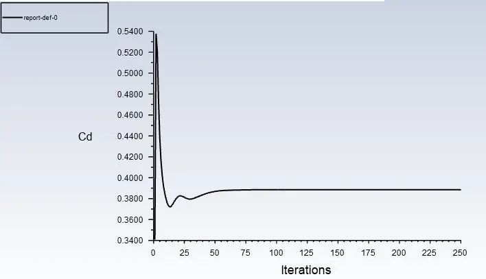
Lift coefficient = 0.2490
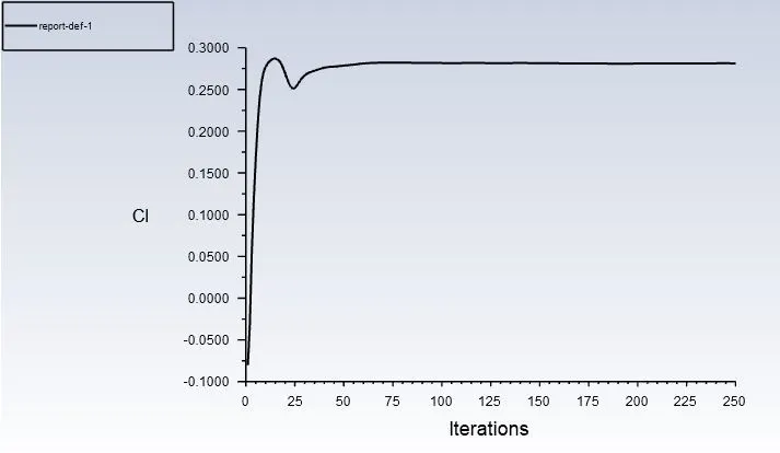
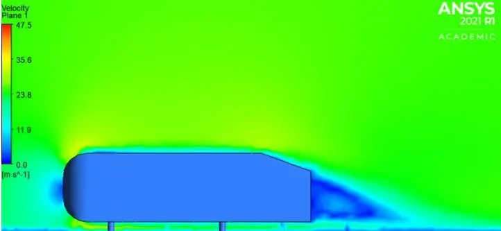
Results:-
Velocity contour:-
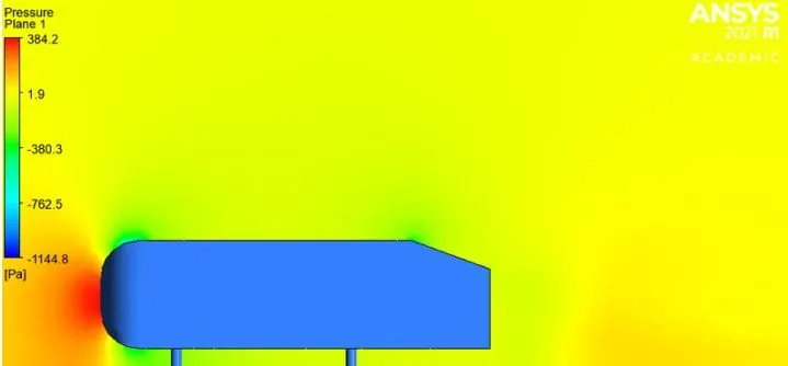
Pressure contour:-
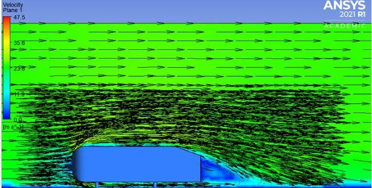
Vector plot :-
Grid independency test:-
| No of elements | Cl | Cd |
| 339802 | 0.2490 | 0.3812 |
| 698547 | 0.2843 | 0.3780 |
| 726100 | 0.2848 | 0.3648 |
Here we check the grid independence test for three different cases. There is no major difference in the values of lift coefficient and drag coefficient as increasing the number of elements.
Conclusion
It can be inferred that the grid independence test is performed to know the smaller cell size for convergence. Apart from mesh refinement, convergence depends on the Y+ value, inflation layer, it is advisable to use kω SST as the turbulence value because it calculates the values well near the wall.
As the setup is refined drag coefficient, lift coefficient decreases.
The negative pressure in the wake region is primarily because there is no flow in that region. This can be further attributed to various factors such as separation and recirculation which is evident from the vector plot near the wake region.
The point of separation occurs at the rear end of the vehicle, the separation occurs beyond this point where it can be observed that the flow recirculates and attaches it to the boundary layer.