Week 3 - External flow simulation over an Ahmed body.
Q.1 Describe Ahmed body and its importance
It is a simplified car body used in automotive field to study the effect of different angles, impact of flow pattern on the drag.
The extrenal aerodynamics is very important in the case of comfort, fuel consumption at high speeds, stability.The flow around the Ahmed body is chracterized by high turbulent and three dimensional flow separartions. Suppose we have CFD simulation results and want to validate those with some standard data, then it is comapred to the experimental data which is available on Ahmed body. And hence , we can calculate the error percentage and also accuracy of the numerical scheme. Ahmed body is simplified car model, used to investigate the flow around Ahmed body and find the wake flow around the body. It is round in shape at the front and it has movable z plane in the rear of the body and has a rectangular box which is in between these two parts. Basically the objective of this simple model is to study the drag production.
Importance of Ahmed body
It represents the simplevehicle volume whihc helps to understand the fundamental physics defined by engineers, the study of drag and lift forces, drag coefficients at certain velocities, pressure differences, seeing and analyzing the vortices, turbulence, Reynold's number is obtained. ANSYS FLUENT is a general purpose software which gives the numerical prediction of the system when we give correct input conditions. Hence, numerical predictions need to be validated by experimental data. Engineers working in vehicle aerodynamics use Ahmend body to validate their numerical model because the experimental data from wind tunnel testing is available for Ahmed body. Once this model is validated, it is used to design new models of the car.
Ahmed's body was orginally described by S.R. Ahmed in 1984. Three main features were seen in the wake region of car model,
1) The A-recirculation region that is formed as the flow separates at the top of the vertical back surface of the model .
2) The B-recirculation region formed because of flow separation at the base of the model.
3) The C- pillar vortices that form as the vorticity in the side boundary layers roll up over the slant edges.
The wake is shown highly dependent upon on the slant angle. For slant angle less than 12 degrees, the flow remians attached over the slant. The flow is essentially 2-dimensional. Between 12 to 30 dgrees, the flow becomes much more 3-dimnesional as C-pillar vortices are fomred. These become of maximum strength at 30 degrees. Past 30, flow separates fully off the slant. This decreases drag and weakens c-pillar vortices.
The geometry of Ahmed body is shown as below,
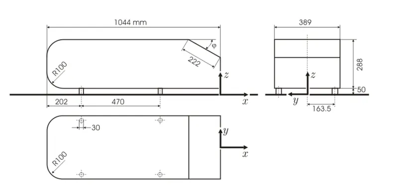
Drag coefficient of the car body is important parameter which has direct impact on power consumption of car engine. It quantifies the resistance of an object in a fluid environment. It is not absolute constant for body shape of car, but it varies with speed, flow direction, object shape and size, density, viscosity of fluid. Lower the drag coefficient of body, lower is the hydrodynamic drag . For more efficient car, Cd must be lower in value. But decreasing the Cd drastically may cause car accidents because of lower road traction.
Certain ways to modify car aerodymanic are removing certain items like roof rack, mud flaps, spoilers, radio antennas. Professional car racers also take off their windshield wipers and side mirrors for better aersodynamic performance.
Procedure:
step 1: Loading Ahmed body in ANSYS SpaceClaim
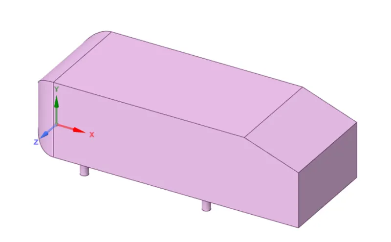
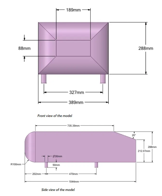
Now as we want to simulate the flow around the Ahmed body, let us make enclosure in SpaceClaim of suitable size which will be affected by body.
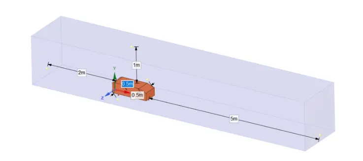
So, after this, there is need of one more enclosure .The reason is ,if we refine this total enclosure, some area of it is not affected by the body, like very top side, air just comes and flows in streamlined way there. So, that is waste of time and computational space/memory also. Instead we can make small enclosure by understanding the wake region of car body which is the region where vortices are seen, velocities may be in opposite direction, also negative pressure. So depending upon that, enclosure sizing is choosen as below,
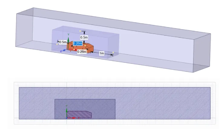
From this above sectional view we can see that, section of the two enclosures are interfacing and hence the meshing will overlap between the enclosures. We have yo fix this problem in spaceclaim itself.
Use interface command , by that we cans solve this overlapping by separating two surfaces. Also enable share option in 'shared topology'.
As we are not interested in the inside of the Ahmed bosy, we will supress it for physics so mesh wont be created inside it and no physics will be applied to it.
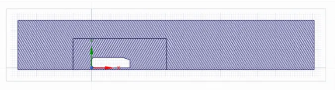
step 2: Meshing
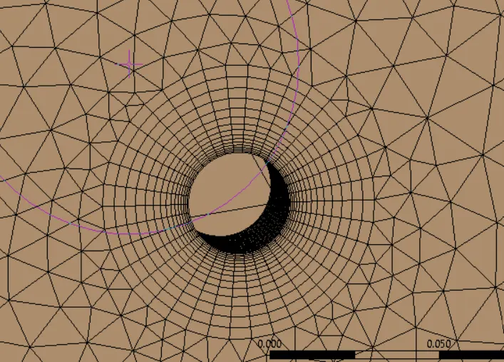
First create the named selection , inlet for front side of Ahmed body, rear side as outlet, top, bottom, left and rght side as symmetry and Ahmed body as car-wall.
The outer enclosure has to be coarsened using 'Body sizing' option as there will not be much flow in that region as mentioned earlier. The inner enclosure has to be meshed finer with 'face meshing'.
Ahmed body has to be meshed even finer to capture flow accurately.
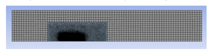
Element count: 439608
Body sizing (car wall) = 4 e-2m
Face sizing = 2.5 mm element size
Importance of Y+
The behaviour of flow near the wall is a complicated phenomenon and to distinguish the different regions near the wall, the concept of Y+ has been set. It is dimensionless quantity. It is distance from the wall measured in terms of viscous lengths.
It is not desirable to have Y+ value in between 10 to 30 since the modelling of flows transitioning from laminar to turbulent is not easy and its being researched.
Hence, it is better to have Y+ less than 10 means at the ALminar region and more than 30 to be in turbulent region.
It can be used as a baseline by which we can decide bas egrid size and make a decision based on computational power as mesh should be coarsened or make finer.
Here, Y+ has been chosen as 50. By using Y + calculator, we get the first layer thickness as 0.00043 m.
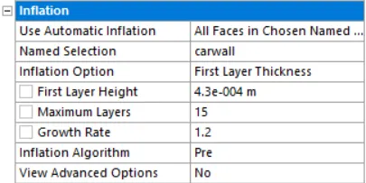
Element Quality:
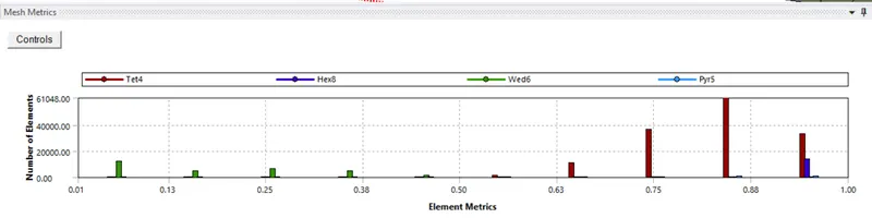
Most of the cells come with quality above 50%. So, it is acceptable mesh.
step 3: Fluent set up:
Pressure based solver is being used for incompressible flows. The density based approach on other hand was originally designed for high -speed compressible flows. Density based solver can give accuracy over pressure based solver for high speed compressible flows. Density based solver solves the equations simulteneously for density, pressure, enery if there. Where as pressure based solver assumes pressure if not given as BC or it takes from BC and then solves continuity equation and gets velocity.
In our case, Mach no is less than 0.3, so flow is incompressible, hence we shall use Pressure based solver.
In viscous model, select k-Epsilon model for turbulence capture.
Simulation will run with default material as air with default properties.
In boundaries, set inlet velocity as 25m/s. Also set up the reference values for calculating drag coefficient and lift coefficient as below,
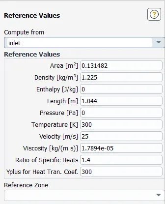
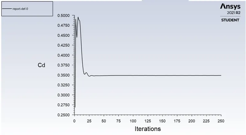
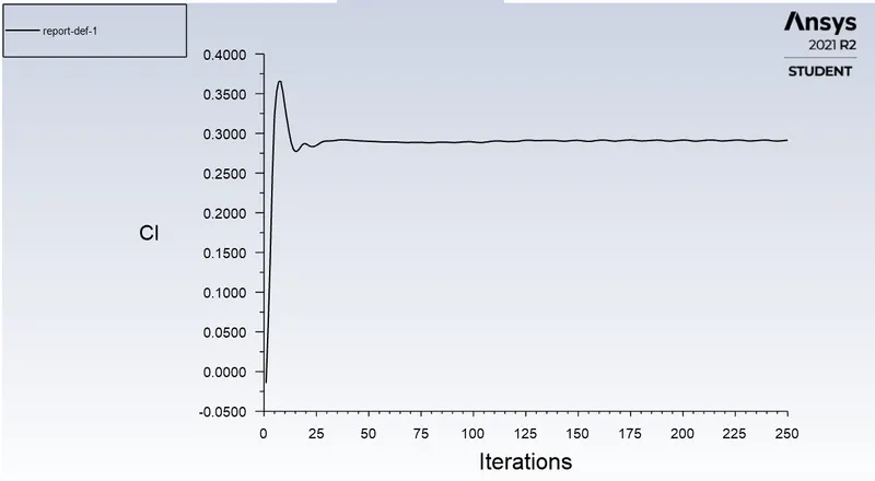
Also, set up report files for velocity and drag , lift coefficients. In results, create a plane by point and normal, called cut plane Z and distance is 1 m from origin.
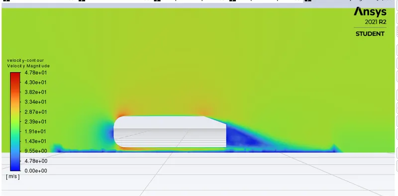
Create contour plots for velocity on cutplane Z.
I ran one simulation as baseline but did get very coarse results, hence I modified the mesh and got below results.
Results:
Y+= 50
Viscous model = k-Epsilon
outer enclosure = 100 mm size of hexa elements
Inner enclosure: 25mm size of tetrahedral elements
car body : 10 mm size of tetrahedral mesh
Inflation layer thickness : 0.00043m
No of elemets: 439608
Velocity contour:
Pressure contour:
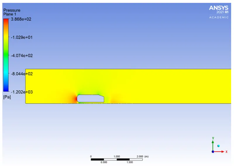
Reason for negative pressure in wake region:
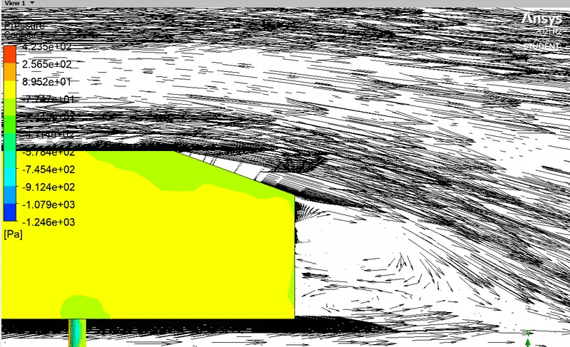
Wake is the region of recirculating flow immediately behind a moving body or blunt body caused by viscosity which may be accompanied by flow separation. The reason for negative pressure in wake body is due to vortices. These vortices are local zones of low pressure that decelerate the body. Negative pressure is a result of dominance of pressure and viscous forces over the accelerating force of fluid. Pressure in the wake region remains close to separation poinbt pressure as eddies can not convert rotational KE into pressure head.
Point of separation
Flow separation is said to occur when the direction of flow velocity near the surface is opposed to the direction of the fress stream velocity, which means du/dy <=0. Such situation arises when there is negative pressure gradient near the wall. Eg is subsonic diffuser or rear of the car. The skin friction coefficient vanishes to zero and at this point, wall shear stress vanishes and called separation point. Reverse flow takes place beyond the point of separation. Due to reverse flow, irregular eddies are formed and lot of energy is dissipated. This is wake region. The pressure distribution in this region is quiate different than that of remaining body. This goves rise to extra drag on body. Wake also leads to lateral vibrations to tnhe object which may be harmful.
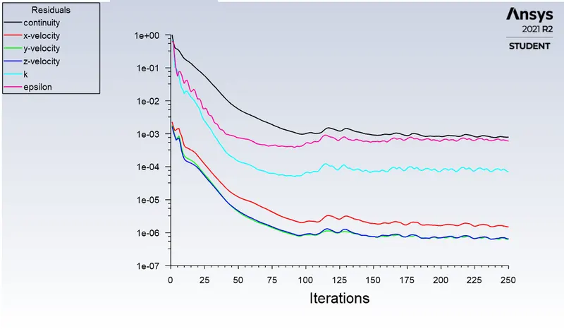
Scaled residual plots:
Velocity profile in two planes at 2m and 3m in axial direction.
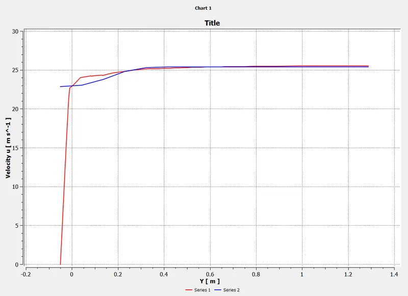
Vector plot showing in wake region of body,
Reference papers:
1) Experiments and numerical simulations on the aerodynamics of Ahmed body.
(PDF) Experiments and numerical simulations on the aerodynamics of the Ahmed body (researchgate.net)
2) Flow and turbulence structures in the wake of simplified car model.