Week - 3 Drop test Challenge
#4 // Week _ 3 Drop test Challenge.
Aim: To Create drop test simulation using LS-DYNA.
Objective:
- To create material for different parts.
- To create section for solid and shell elements.
- Assigning material and section ID to parts.
- Create Boundary conditions.
- Create Contact between phone and plate.
- Assigning initial velocity to phone.
- Control simulation time, recording animation, plots, etc.
Introduction to Finite Element Analysis:
The finite element method is a numerical technique for obtaining approximate solutions to a wide variety of engineering problems. FEA (Finite Element Analysis) is done in three phases.
- Pre-processing.
- Solution.
- post-Processing.
Drop test: The most common failure of cellular phones is probably the impact due to accidental drop, so the manufacturers aim to develop products that are impact resistant and can survive the drop test from a specific height. Both physical tests and finite element (FE) simulations are employed in the industry at different stages. At the design stage, the FE method plays a more important role since the actual drop test can only be conducted at the end of the design cycle and provides little feedback to improve the design. The FE simulation will help designers understand how components interact in the assembly and how the failure mode and mechanism are developed under impact loading.
Procedure:
1. Import: Import (".k") file as shown below. Go to file >> open >> LS-DYNA keyword file.
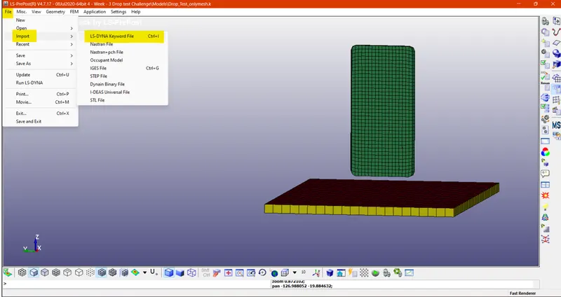
- These are the Keywords present in the imported model.
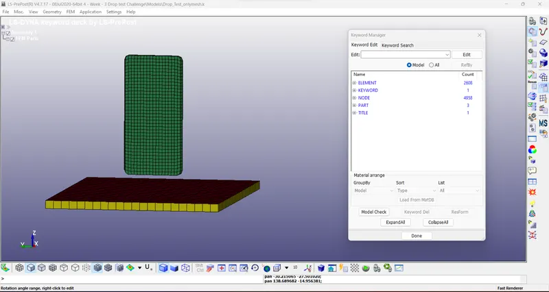
2. Creating Boundary: In order to run a simulation, we need certain boundary conditions such as constraints and initial parameters such as velocity, etc.
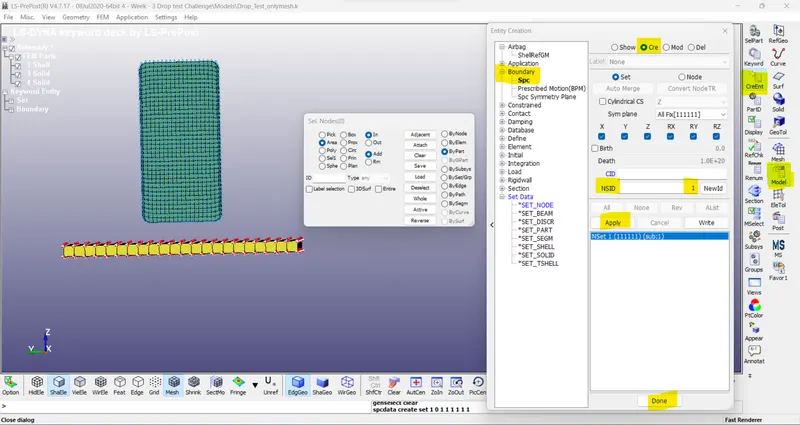
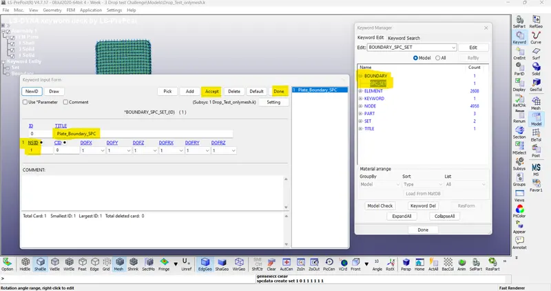
- First create two different node set IDs. One NSID consists of all elements of the plate which are used as (SPC) Single Point Constraint and the other NSID is to represent a set of all phone elements which are later given initial Velocity.
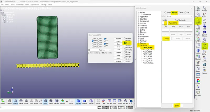
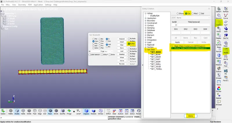
- Now, create a boundary SPC and select NSID and then apply.
- Material Creation:
- Every part is made up of material. We should create the material properties accordingly and assign those materials to their respective parts.
- We are using the kg-mm-ms unit system, all the data which is input should be in the same unit system.
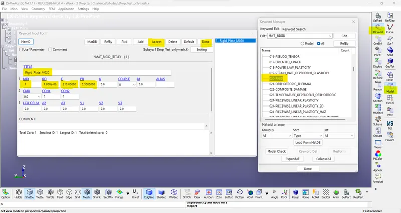
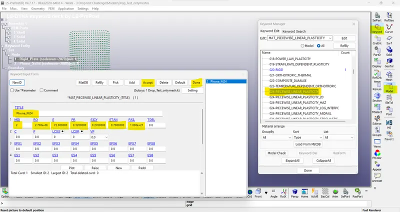
- Create material for a plate which is rigid Model and Part > MAT(all) > 020_rigid plate. and for the phone here considered aluminum (024_picewise_linear_plasticity).
> Rigid_Material(M020)
> Phone_Material(M24)
4. Section Keyword:
- In order to define the type of element i.e., shell, or solid, we must define the section keyword.
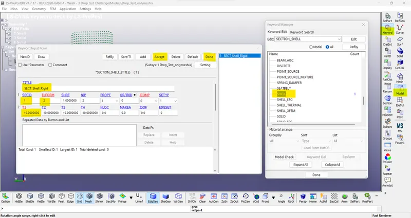
- Section is created using Model >> Part >> section(all) >> shell. Here we should give thickness and type of element formulation here is not important because all nodes are fixed in all directions, therefore no element undergoes displacement.
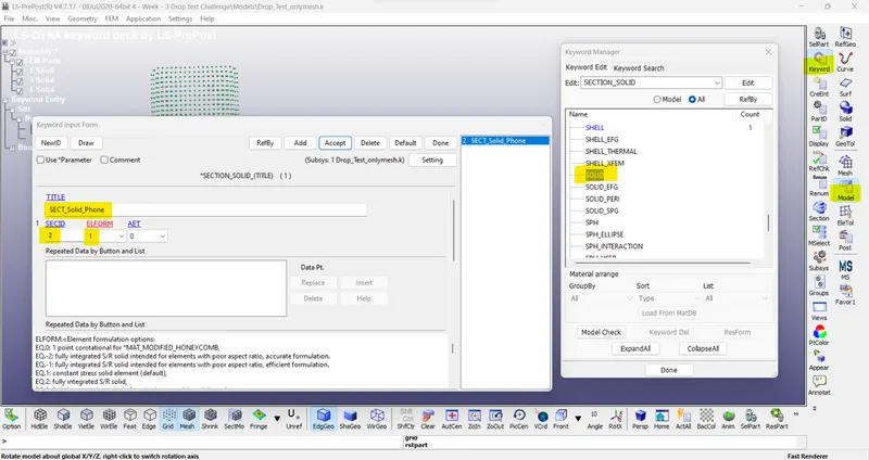
- Section is created by (Model and Part>section(all)>solid).
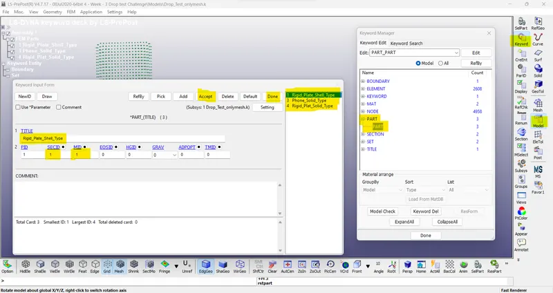
- Assigning Material and section: one done with Material and section we can assign those data to the parts by directly clicking on part in (Model and Part>part) so we can see the part list and each part has the option to select for Section ID and MATID.
- Initial velocity:
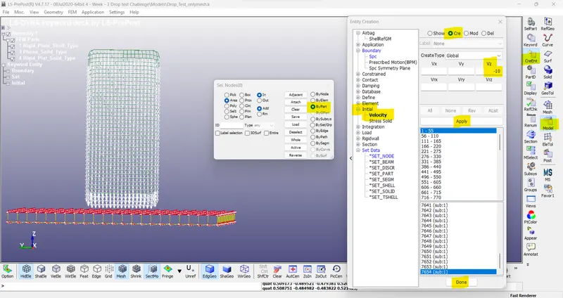
- In order to move the phone against the plate we must assign an initial velocity of 10 mm/ms in a negative z-direction. Select the node set and input the velocity in which direction it should move as shown below.
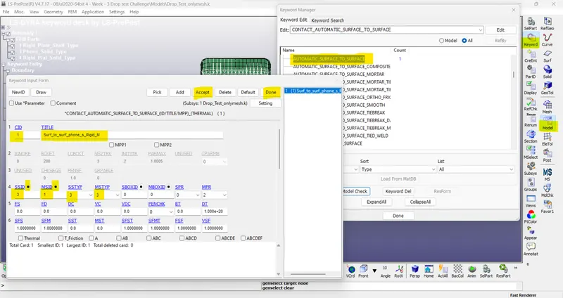
- Create Contact:
- Impact will take place between the phone and plate, only if there is a contact defined between them, or else the phone will go through the plate.
- All phone element nodes are taken as slave and all plate element nodes are taken as master nodes.
- Control setup:
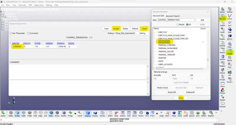
- In LS-DYNA pre-post, *CONTROL_TERMINATION card is used for defining the simulation time.
- Simulation is set to run for 5ms, this is the rate at which the phone drops to the ground.
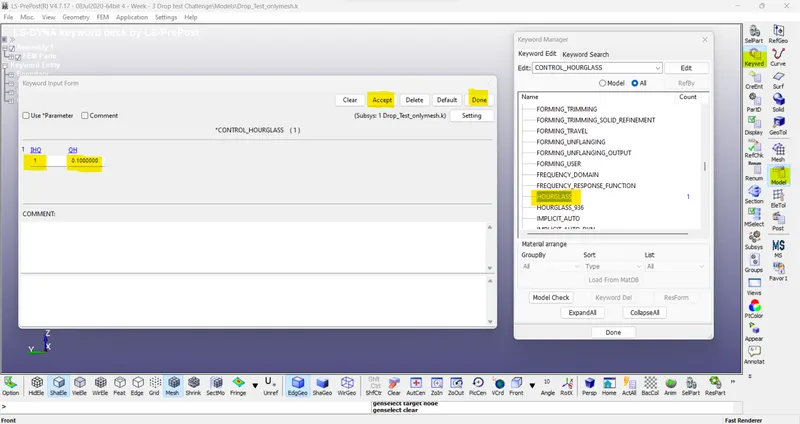
- Hourglass is defined as deformation that occurs without strain.
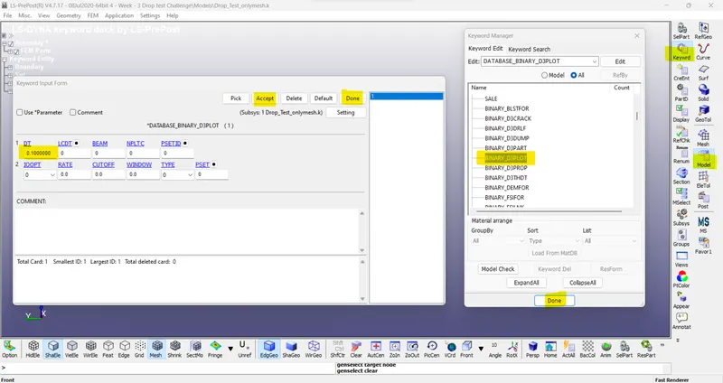
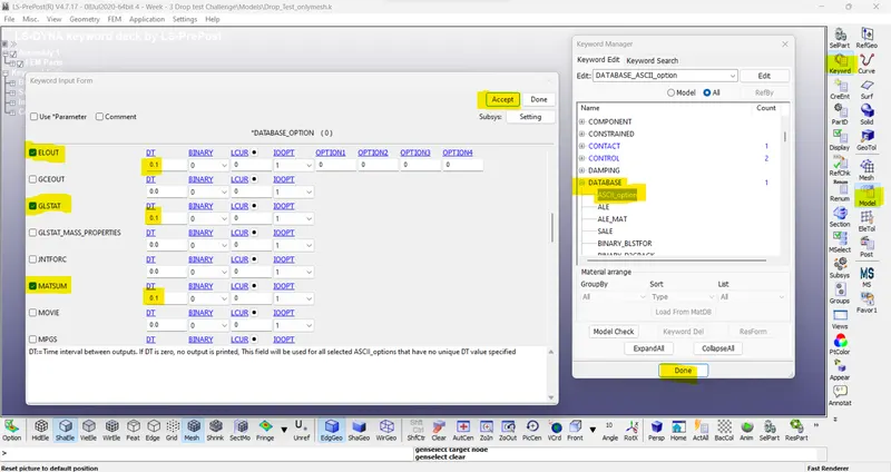
- Output Request: Using database pannel we can request such as animation file energy data, contact forces, etc.
BINARY3DPLOT - The complete state dump interval as given in *DATABASE_BINARY_D3PLOT serves as the time step to be used in the material model driver run. Plotting information is saved in the core for the interactive plotting phase.
ASCII_option- This option is used to read the data of the following ..
ELOUT - This latter option will output all integration point data or extrapolated data to the connectivity nodes in a file call outlet.
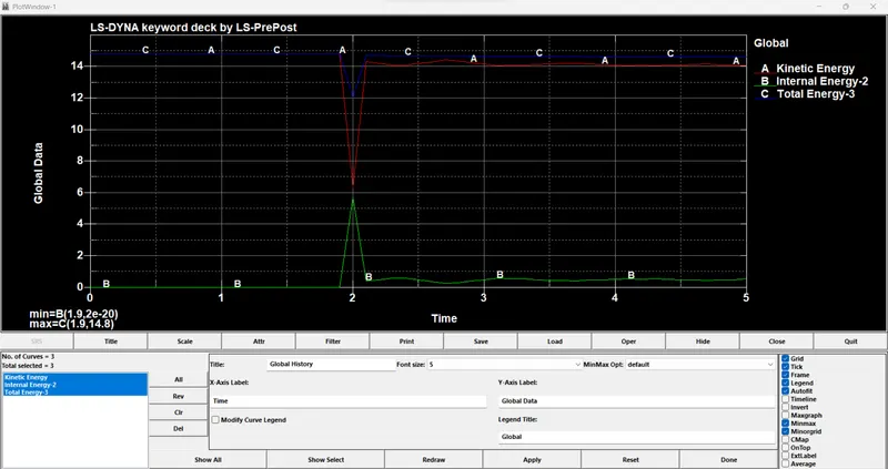
GLSTAT - Reade the energy like KE, PE, IE.
MATSUM - Every material part energy due to deformation.
RCFORCE - contact force b/w them.
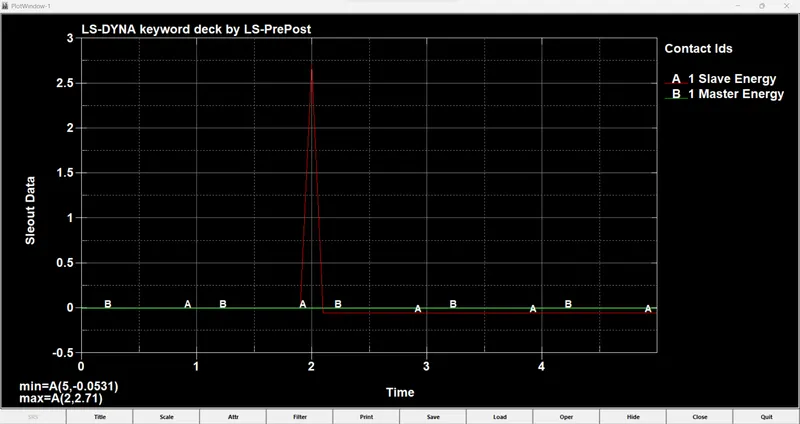
SLEOUT - sliding force due to contact.
SPCFORCE - single point contact force.
- Solving the setup:
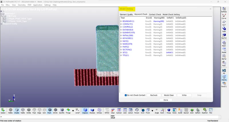
- The model is checked for any errors before solving using a model checker. After all the errors are cleared, the drop test setup is saved and is ready to run in LS DYNA manager for solving the scenario.
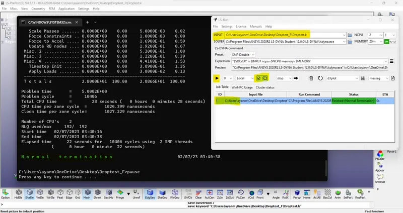
- The saved keyword file is selected as input to run in LS-RUN. Normal termination of the run is achieved and is ready to analyze for post-processing.
11. Post Processing:
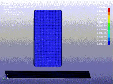
- Input the d3plot file and we can see all the output results which we have given earlier.
- Animation and plots can be seen and saved easily using LS-PrePost.
- Initially we can say that the velocity is maximum therefore kinetic energy is also maximum. But during the impact, kinetic energy is absorbed by the part and it decreases, simultaneously internal energy increases (in the middle).
- After impacting with the rigid body, it rebounces back with the same velocity, ie., K.E increases and I.E decreases
- We can see that the phone body i.e., slave energy increases to a maximum at the time of impact and reaches below master energy after the impact but the rigid body i.e., master nodes energy remains constant during the entire simulation.
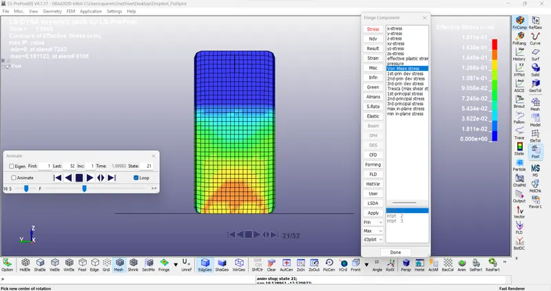
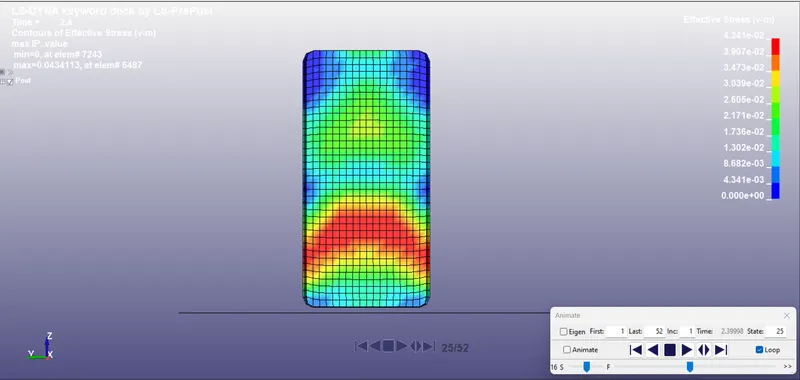
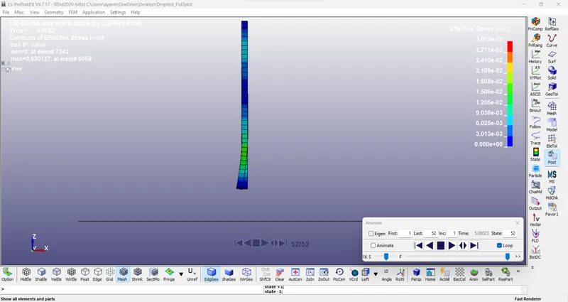
// After simulation we can see bend in phone and.
> The maximum effective stress at the time of impact was found to be 4.341 e-02 kg/(mm*ms^2).
Conclusion:
The main aim of the Week 3 challenge was to create an input deck or setup file to perform the drop test of a cell phone using LS-DYNA software and analyze the behaviour of stress-strain and other results while and after the cell phone hits the plate (mimicking ground). The maximum effective stress at the time of impact was found to be 4.341 e-02 kg/(mm*ms^2). From the GLSTAT plots, it was found that the simulation setup follows and validates the principle of conservation of energy expressing loss of kinetic energy of mobile phone conversely leads to the gain of internal energy of the plate (ground).