Week - 3 Drop test Challenge
Aim:
To create an input deck from scratch and creating results similar to the situation, where the phone would bounce back in the same direction after the impact.
Procedure:
1. Open the given model:
The given file is opened using File --> Open --> LS-Dyna Keyword file 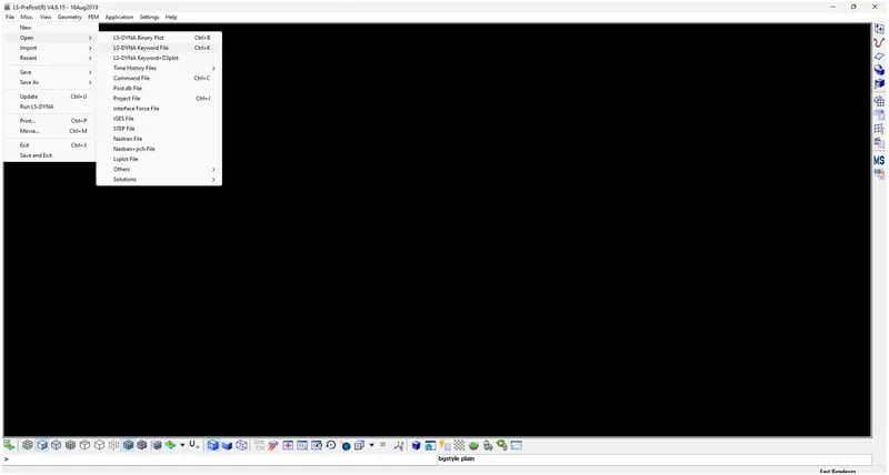
2. Material card creation:
- Select Keyword Manager present on the right side of the tool bar
- Once the keyword manager window opens, select ALL
- Go to MAT --> Select 001-Elastic --> Keyword Input Form window opens
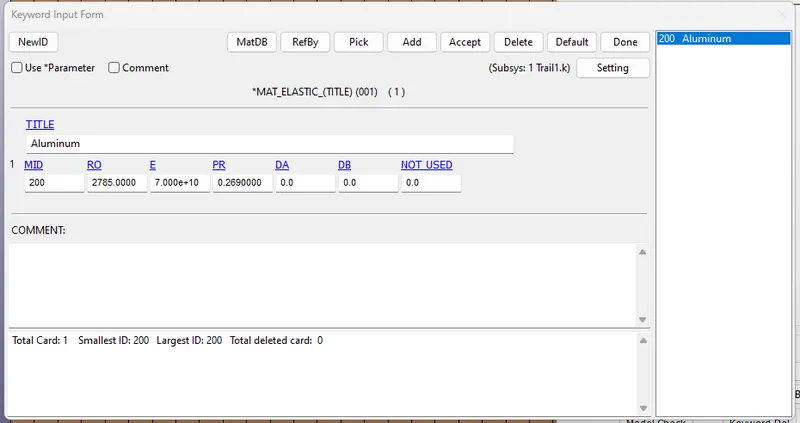
- In the Keyword Input form window, enter the Material name in TITLE, a unique material ID in MID and the other material properties like density, Youngs Modulus and Poission ratio. Unit of measurement followed in this project is kg-m-s. Material for the phone is chosen as Aluminum and its properties are entered in the material card.
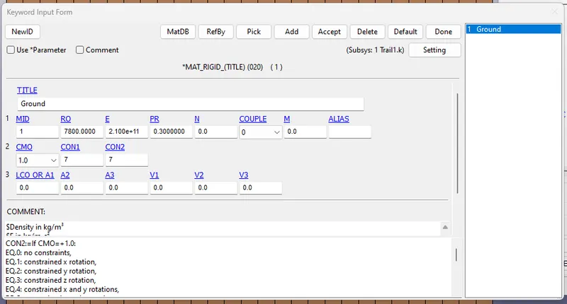
- Similarly, the ground is considered as a rigid material. So, MAT --> 020-RIGID is selected. Steel is considered as the material for the ground and its properties are entered. Also, a unique material ID is created for it. The ground is considered as a body that does not rotate or translate. Hence, corresponding values for it are entered in CON1 and CON2 fields.
3. Section card creation:
- The model contains two parts - Phone and ground.
- Phone is considered as a solid part
- Ground is considered as a shell part
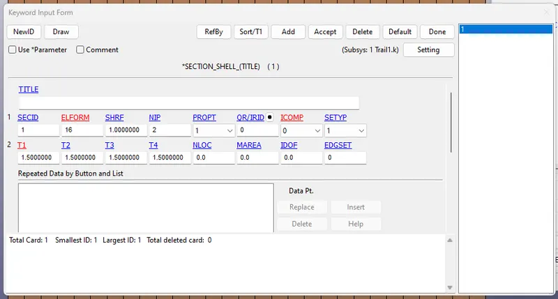
- Ground section creation - In the Keyword manager, select All --> Shell --> Keyword Input Form window opens --> Enter SECID, ELFORM, T1, T2, T3 & T4 --> Select Accept --> Done
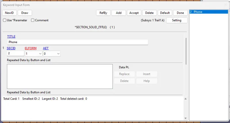
- Phone section creation --> In the Keyword manager, select All --> Solid --> Keyword Input Form window opens --> Enter TITLE, SECID, ELFORM --> Select Accept --> Done
4. Part card creation:
- In the Keyword manager, select All --> Part --> Enter TITLE --> Enter PID --> Select the small dot button near SECID --> Select the correct section in the link section window --> Done --> Repeat the same in MID field and select the appropriate material --> Select Accept --> Select Done
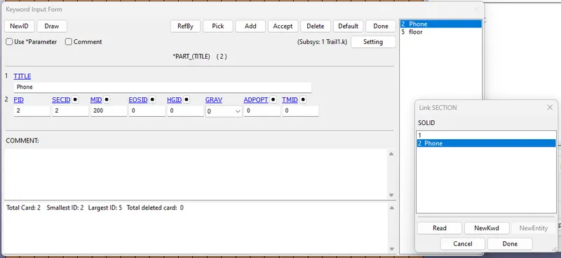
- Repeat the process for the second part.
5. Initial Conditions:
- In the Toolbar on the right side of the window, select Create Entity
- Select Initial --> Velocity
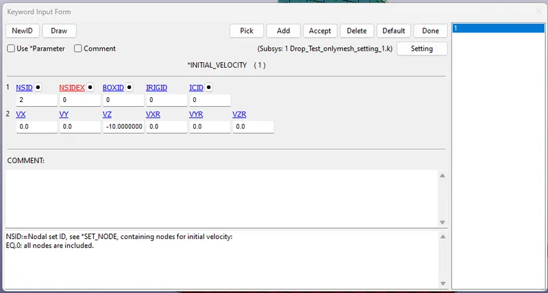
- In the Keyword Input form window, enter the velocity Vz as -10 m/s --> select Accept
- Select the dot button near NSID --> Link_SET_NODE window opens --> Select NewEntity --> Entity creation window opens
- In the Entity creation window, select Pick --> Select ByPart --> Select the phone part --> Apply
- In the Keyword Input form window, select Accept --> Done
6. Contact card creation:
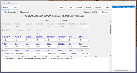
- In the Keyword manager, select All --> CONTACTS --> AUTOMATIC_SURFACE_TO_SURFACE --> Enter CID & TITLE --> Select "3" which denotes Part ID in SSTYP & MSTYP --> Select Phone body as slave in SSID & Ground body as Master in MSID --> Click Accept --> Done
7. Control card creation:
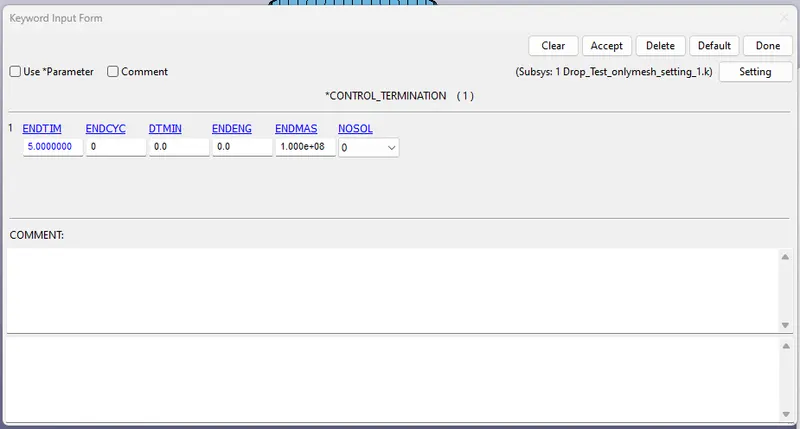
- In the Keyword manager, select All --> CONTROL --> TERMINATION --> Enter ENDTIM value --> Click Accept --> Done
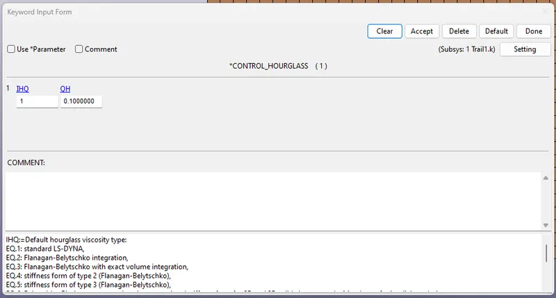
- In the Keyword manager, select All --> CONTROL --> HOURGLASS --> Enter THQ as 1.0 --> Click Accept --> Done
8. Database card creation:
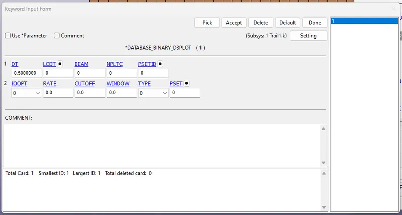
- In the Keyword manager, select All --> DATABASE --> Select BINARY_D3PLOT --> Enter DT as 0.5 --> Click Accept --> Done
9. Save the file using File --> Save --> Save Keyword as a .k file
10. Run the .k file using File --> Run LS Dyna --> LS Run window opens --> Select the saved .k file in the INPUT field --> Select the "Add job to local queue" to run the simulation --> A command prompt window opens --> Once the simulation is done, the processing in the command prompt stops
11. View the output:
- Select File --> Open --> LS Dyna Binary Plot --> Select the file
- In the right side toolbar, select Fringe Component --> Fringe Component window opens
- Select the required output and animate the simuation using the options in the animate window
- Similarly, using History option, the information an element/part can be viewed as plot
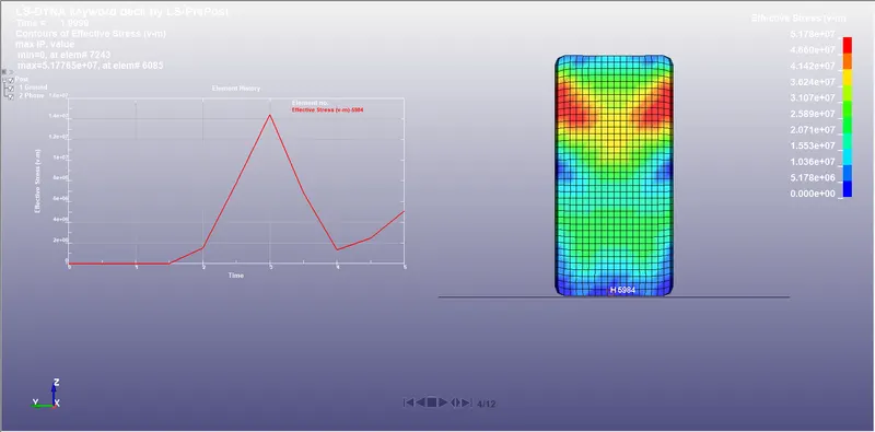
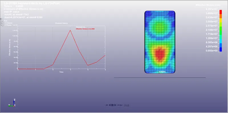
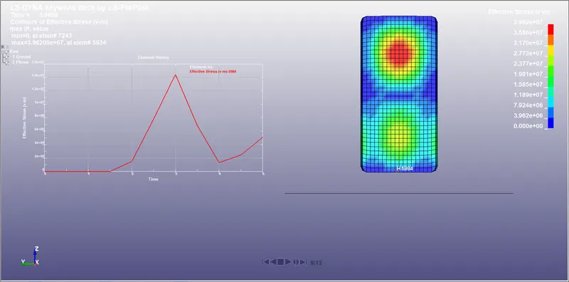
- In the below picture, one of the bottom element of the phone is selected and observed for the effective stress at that point. The stress at that element is maximum at 3 sec and the build up of stress sat that element tarts at 2 sec. It is to be noted that the time at which the phone impacts the ground is at 2 sec and the maximum stress induced in the element is at 3 sec. After 3 seconds, the stress at the element starts decreasing and then starts increasing again at 4 sec.
Learning outcomes:
- The procedure for creating keywords using keyword manager
- Setting up the simulation with appropiate keyword after understanding the scenario to be simulated
- Extraction of results from simulation using plots
Conclusion:
An input deck from scratch is created and results similar to the situation, where the phone would bounce back in the same direction after the impact is created.