Week - 3 Drop test Challenge
OBJECTIVE OF THE ANALYSIS: The objective of the analysis is to understand the response of the phone due to impact.
Aim: To set up a drop test of phone and analyse the response of the system in terms of stress and displacement.
Explaination:
- first step is to mesh the given cad model, since pre meshed model is provided it is skipped .
- second step is to set up the deck for runing the analysis.
- third step is to check for errors ,ie model check and then run the solver
- Fourth step is to postprocess i,e analysing the results.
Setting up the model :
consider a mobile is dropped at a velocity of 6m/s on a rigid floor let us consider phone is made of steel and material data is as follows: density-7850 kg /m^3 ,youngs modulus -2.09e^11n/m^2,possions ratio-0.29 ,yield stress-5e^8 ,Etan -1e^10
and for rigid material density-8e-9 kg/m^3, E-2.1e5, PR- 0.3
we are using piecewise linear plasticity for phone( mat024) and for floor rigid material(mat020) is used.
using single point constrain (spc) the floor mesh is constrained at the edges.
section is defined by section card in keyword manager selecting element formulation 2 for solid elements i,e fully integrated reduced solid for both phone and floor and then assigining material and section to parts.
using keyword manager initial velocity is assigned to mobile in negative z direction by selecting part id of phone.
now in database we need to select binary D3 plot and Ascii card for output result select dt as 0.1 which refers to write output at every 0.1 second until termination time . we are using termination time as 10ms in control termination card so that the analysis runs for 10 ms.
The model setup is complete now model check is done in keyword manager to check for errors.
next step is to run the solver. after successful completion of analysis run now open D3plot ie the animation file to check the stress and displacement plot using fringe component.
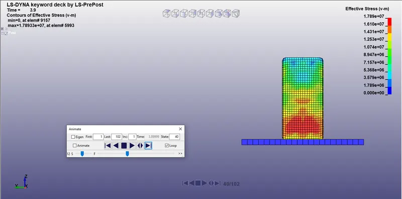
From the above stress plot the highest stress value is 1.789e^7n/m^2 at the impacting end represented by red colour on the model.
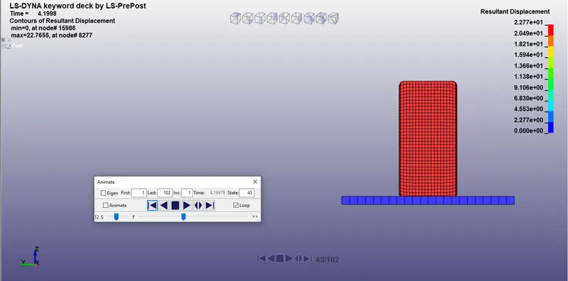
from the above displacement plot the maximum displacement is 2.277e^1 m at the impacting end visualised by crushing of elements at the impacting end.
Conclusion: The max stress is 1.789e^7n/m^2 and max displacement is 2.277e^1 m at the impacting end.