Week - 3 Drop test Challenge
Week - 3 Drop test Challenge
Aim: Simulate the given drop test model by assigning the appropriate key cards.
Explanation:
The given model has only the nodes and element data and this drop_test.k file is imported into LS Dyna prepost from file -> open
For this simulation to run we need a certain keycards to be present which are mandatory.
- Section card for defining the shell or solid
- Material card for determining the time steps
- Boundary conditions/constraints for constraining the elements or nodes
- Intial or imposed conditions for having velocities, displacements or acceleration
- control cards for defining end time.
- contact cards for defining type of contact
- Database card for outputs request.
After importing the file into prepost, first the parts are identified from model and part -> part data
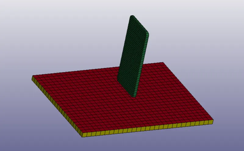
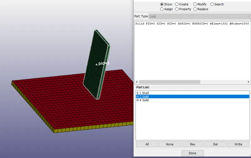
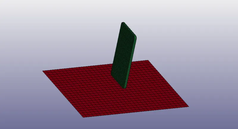
From above image the additional shell or solid for the ground surface is removed to avoid clashing and the part id's are noted.
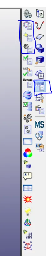
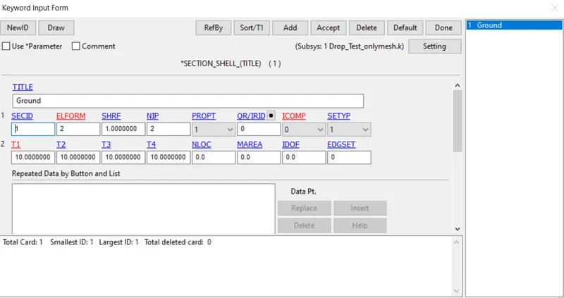
1) Defining Section card for shell and solid from key word manager -> all -> section -> shell
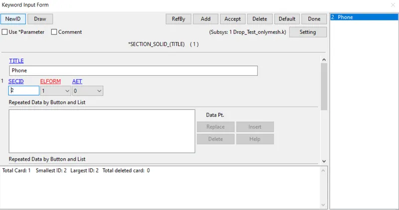
Similarly for soild
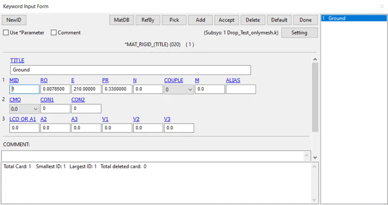
2) Material card generation from key word manager -> all -> MAT -> Type 20 for rigid ground surface which is not deformed.
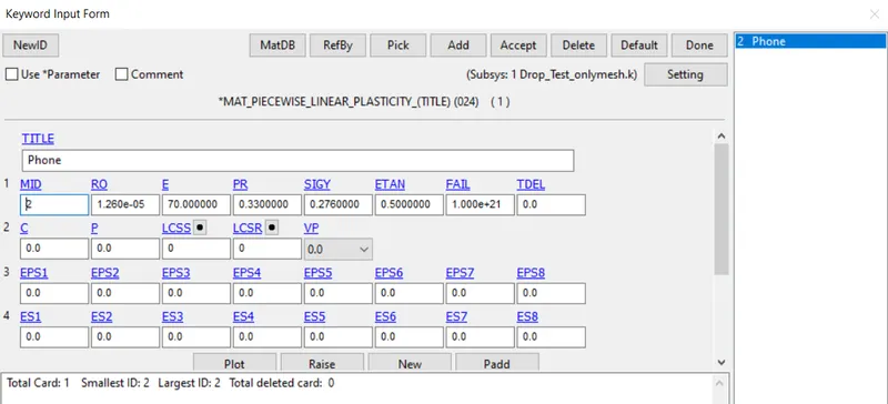
Similarly for phone material Type 24
After the section id and materail id are created, they are then assigned to the parts in the model.
From key word manager -> model -> PART in SECID and MID for both phone and ground
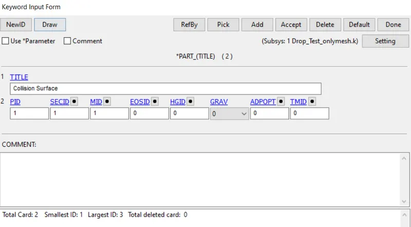
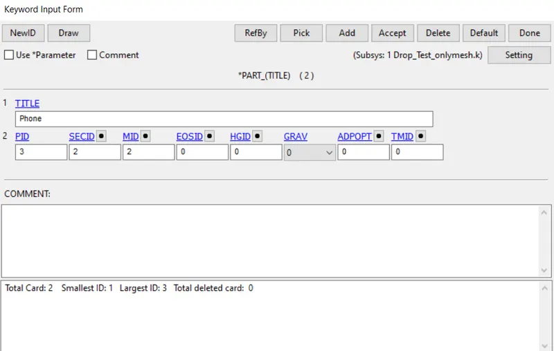
3) Boundary conditions and constraints
This boundary conditions for the ground surface is taken to be rigid and so all degree of freedom are arrested
From Model and Part -> Entity Creation
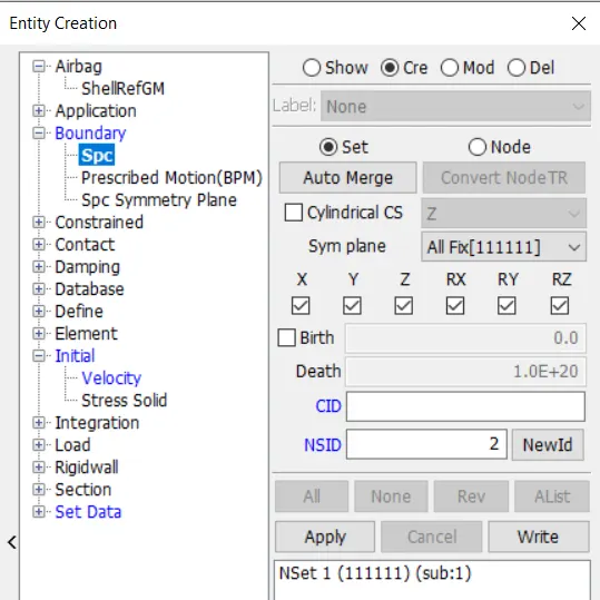
Here Boundary -> Spc is created by picking all the nodes on the ground part and all their DOF are arrested.
4) Intial Velocity
This velocity for the phone is taken to be in -ve z axis direction and all the nodes of the phone part are picked
From Model and Part -> Entity Creation -> Intial -> Velocity
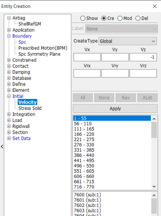
5) Control cards
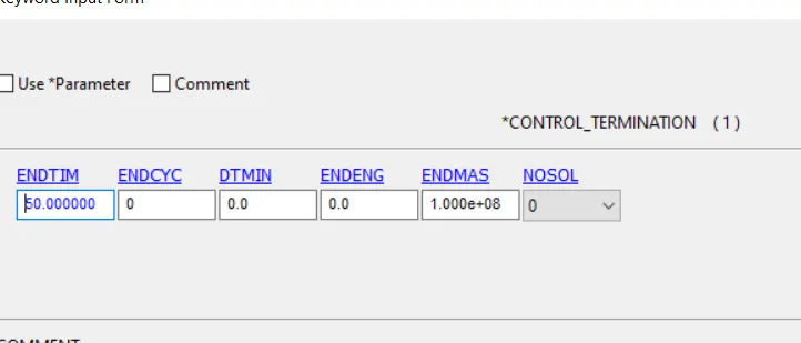
After the boundary conditions, control cards are chosen fron keyword manager -> all -> control -> Termination
The end time is chosen to be 50 ms.
6) Database card
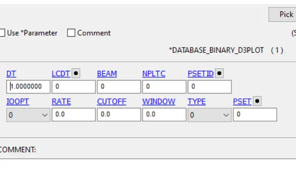
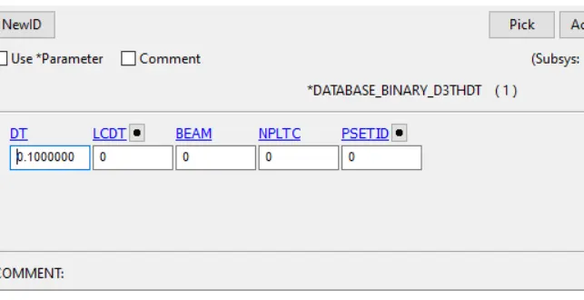
After the control card for end time, the output requests are updated from Keyword manager -> all -> Database ->
Binary_d3plot for contours and animations
Binary_d3thdt for plotting graphs
The energy values, forces on parts, nodes are updated in ASCII
ELOUT for elemental output
GLSTAT for energy values
NCFRC and RCFRC are nodal and Resulatant Interface forces
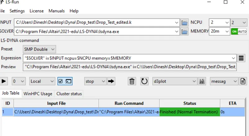
7) After this keyword cards are created and updated, then this keyword file is saved.
Then opening LS RUN and choosing the modified keyword file and run
Results:
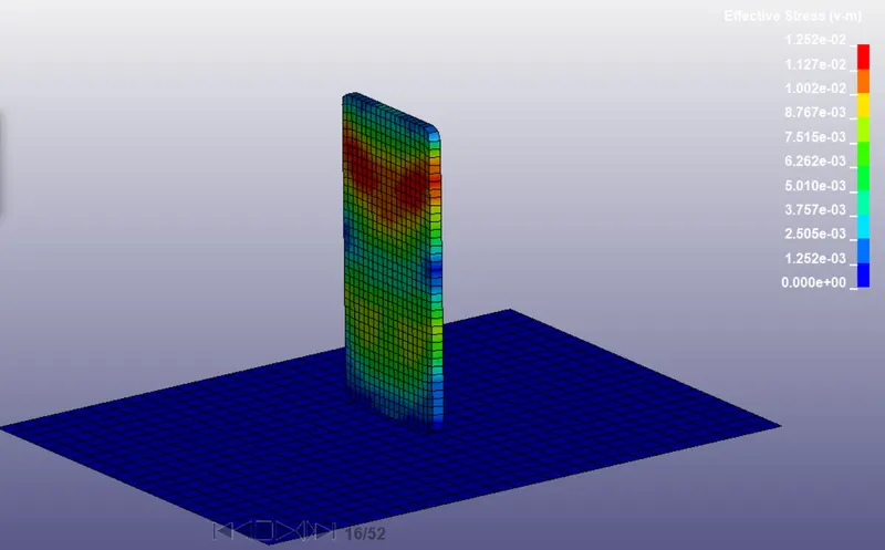
The d3plot is opened as binary file in LS prepost and following max stress contour is obtained around time of impact.
The plots are taken for energies from history -> Global -> Plot
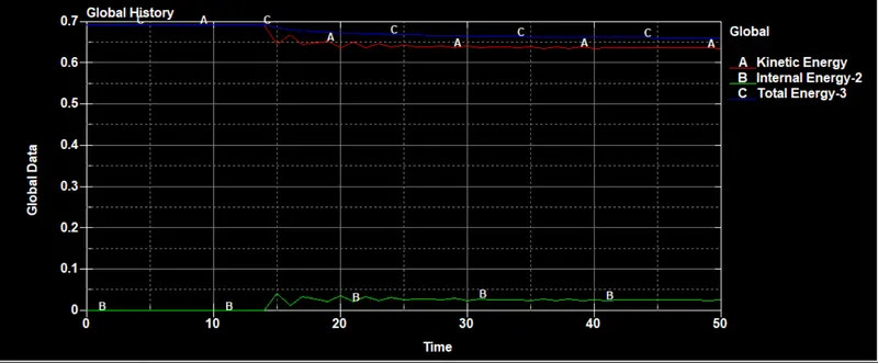
We can see the Internal energies are constant till impact and is suddenly increased due to impact ans vice versa for Kinetic Energy.
Contact Force graph is sown below:
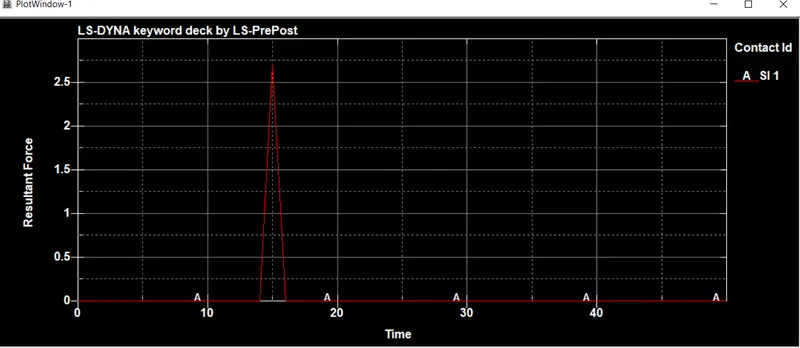
We can see the sudden increase in contact force when phone strikes ground and is decreased to zero.
Conclusion:
The given drop_test is successfully simulated in LS Dyna.