Week 3 Challenge : CFD meshing on Turbocharger
Objective:-
For the given model, check for the geometrical errors to make appropriate volumes. Create and assign PIDs as shown in the video. Perform surface mesh with the given target lengths as per PIDs.
- Blade stage-1 = 1 mm
- Blade stage-2 = 1 mm
- Impeller = 2 mm
- Shaft rotor = 1 mm
- Turbo casing = 5 mm
- Compressor casing = 5 mm
- Inlet casing cover = 5 mm
Procedure:-
Importing the Turbo-charger model.
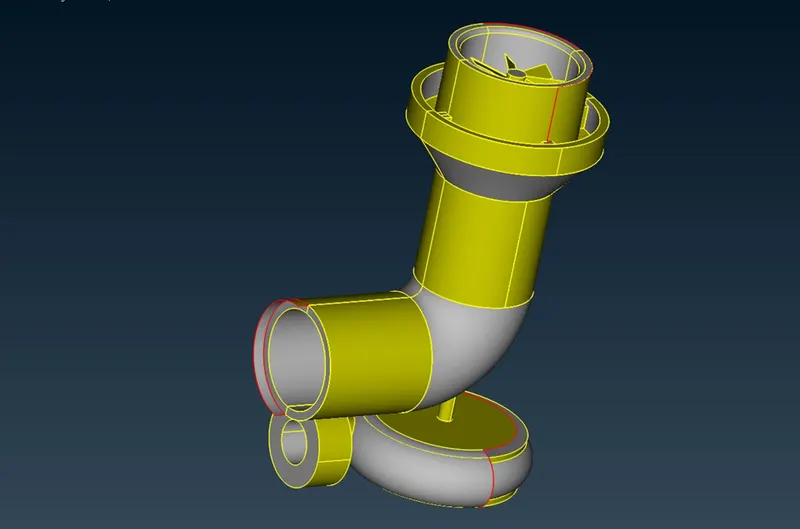
Starting with the Topo cleanup by doing geometry checking to find single and Triple cons in the geometry.
Filling up the surfaces and cleaning the single cons by creating new surface wherever required.
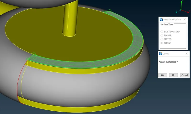
In certain areas it is difficult to create the whole surface at once. So to create the surface, first creating hot points at the desired locations and then creating surfaces one by one.
Deleting the surfaces which are overlapped and also deleting the extra surfaces which intersect each other.
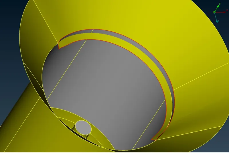
Before meshing, checking the geometry for any single cons
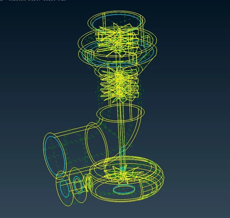
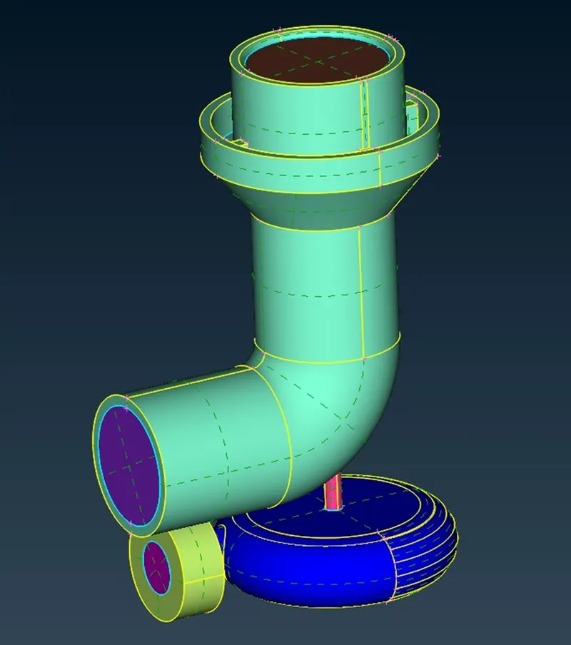
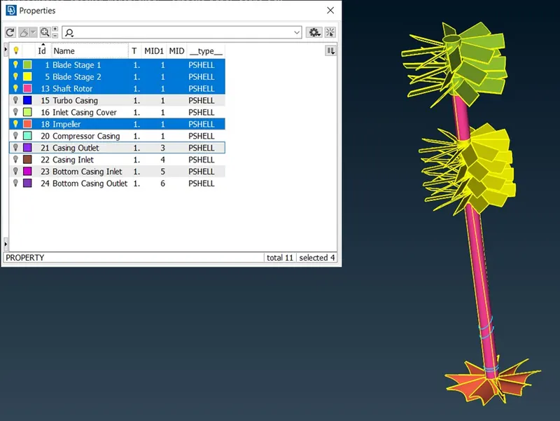
Assigning PID’s
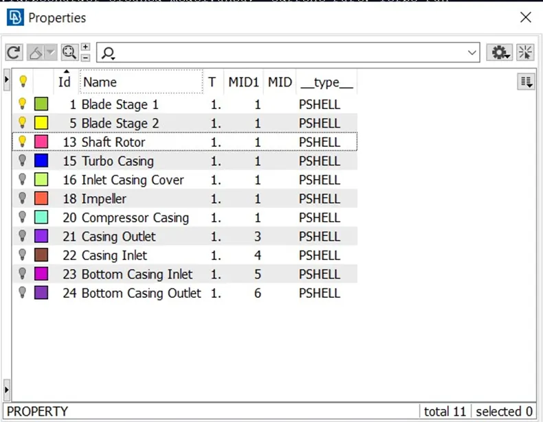
To assign PID to a given surface, right click the name and click on apply. After that click the surface to be assigned and then press the middle mouse button.
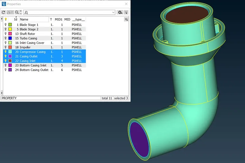
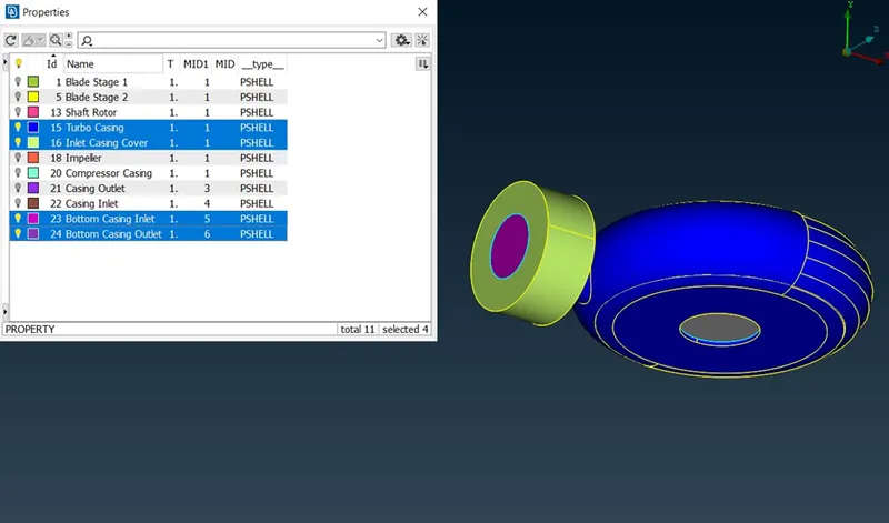
Below is the list of PID’s for various surfaces.
Surface Meshing
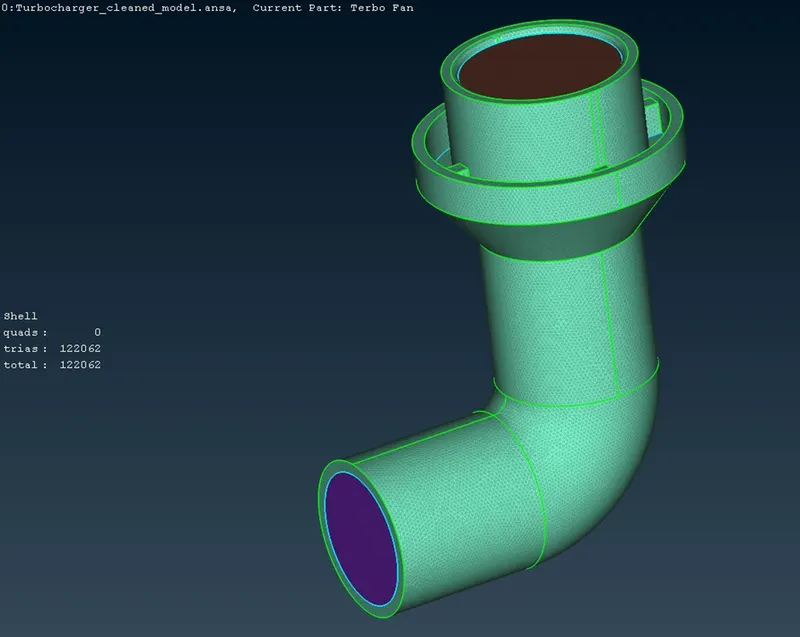
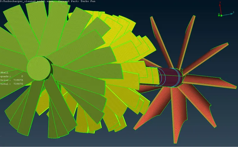
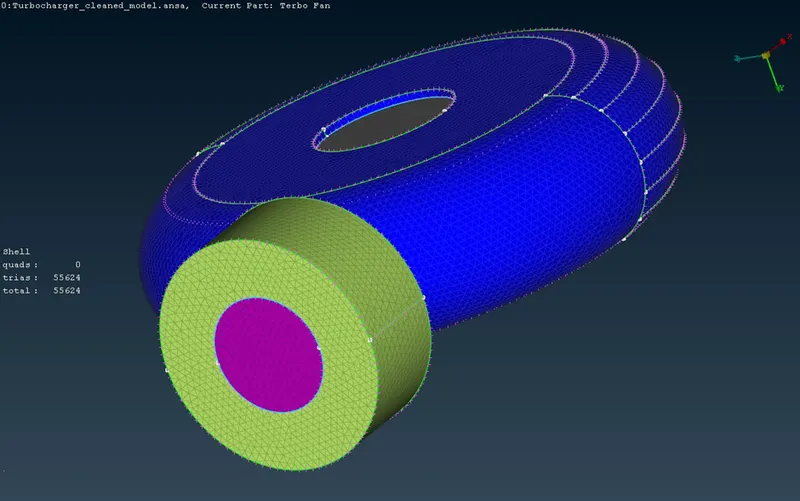
To mesh the given geometry we will provide the target length as 1mm, 2mm & 5mm one by one to each of the following parts of the Geometry.
|
Geometry Part |
Target Length(mm) |
Minimum Length(mm) |
Maximum Length(mm) |
|
Blade Stage 1 |
1 |
0.5 |
2 |
|
Blade Stage 2 |
1 |
0.5 |
2 |
|
Impeller |
2 |
1 |
3 |
|
Shaft Rotor |
1 |
0.5 |
2 |
|
Turbo Casing |
5 |
3 |
7 |
|
Compressor Casing |
5 |
3 |
7 |
|
Inlet Casing Cover |
5 |
3 |
7 |
Setting the Element type as ‘Tria’
In some areas where the shaft meets the component having different target length, the mesh will adapt such that there is a connectivity between the two components.
Volumetric Mesh
For volumetric meshing we will proceed to the icon just adjacent to the surface mesh. In that under Volumes click Define and select the entire Database and press ok.
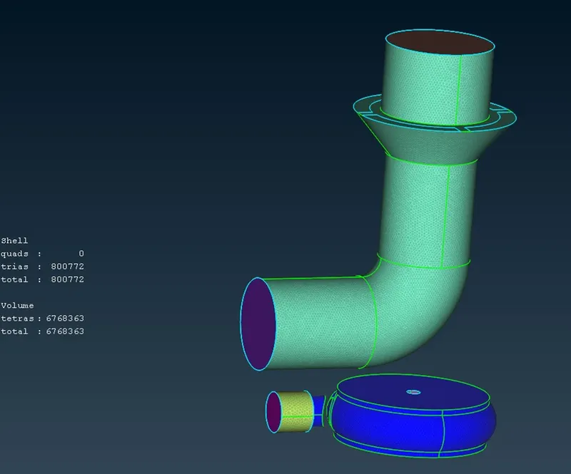
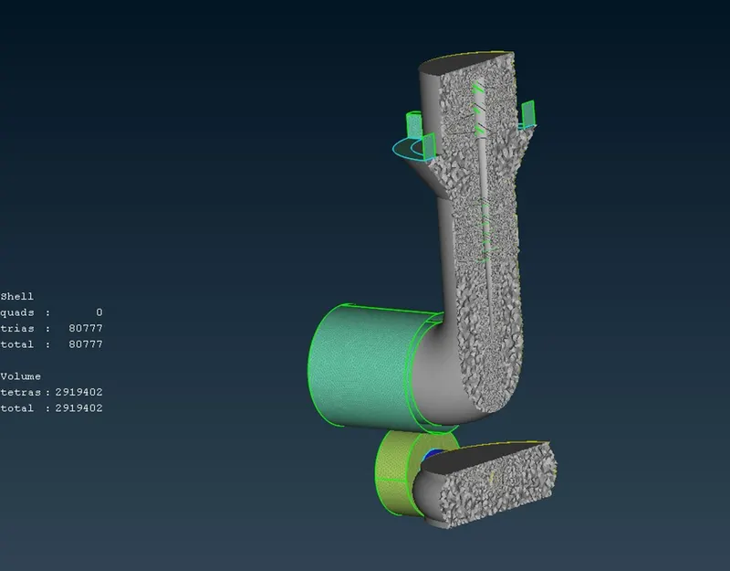
The autodetect feature will detect 8 volumes. From that we need only 4 volumes in which the fluid would flow. Deleting the unwanted 4 volumes which represents the thickness of the two components and the Shaft and blades.
The volumes to be kept are shown below.
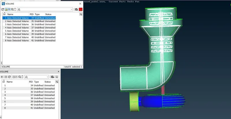
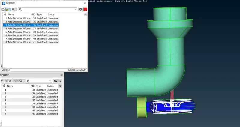
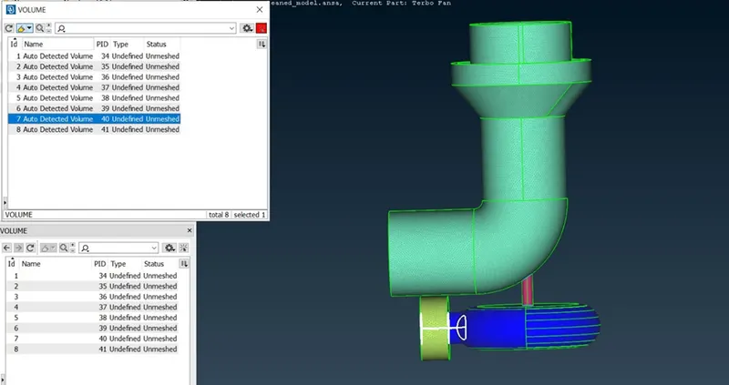
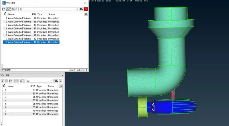
Once the required volumes are extracted, right click on these and select mesh and then select the type of application which in this case is Tetra CFD.
Conclusion:-
Achieved volumetric mesh of the turbocharger model.
Different mesh length tend to give errors at the contact regions of 2 different mesh length regions, therefore mesh ranges can be given to avoid erasing of the mesh.
Volumetric mesh can be achieved only after creating surface mesh successfully.
Overlapped surfaces are deleted by using the universal delete option.
Google drive link:- https://drive.google.com/drive/u/2/folders/1ncWn4ftZ3001WbkP7ABQGlIwl5ZO1GhG