Week 3 Challenge : CFD meshing on Turbocharger
Aim :-
To deploy the CFD mesh on the turbocharger and generate volumetric mesh for the required volumes. of the turbocharger
Steps :-
i. Import the CAD file.
ii. Display setup.
iii. Geometry clean up/Repair.
iv. Geometry check up.
v. Assigning the PID
vi. Defining element size of mesh.
vii. Generate surface mesh.
viii. Generate CFD volume mesh.
Procedure :-
i. Importing CAD file -
Go to file > Open > Browse the location of the model > Select it and click enter.
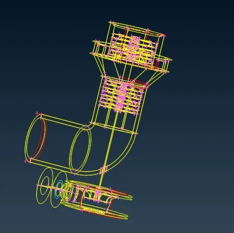
ii. Display setup -
As we can see the imported CAD file is in wire frame. We need to set it right for use.
Bottom tool bar > Shadow.
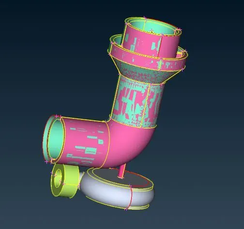
iii. Geometry clean up/Repair -
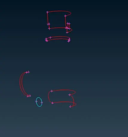
As we can see there are several single cons present. Single cons means there is only one surface. So we can turn the single cons into double cons by adding new surfaces over there by doing some operations.
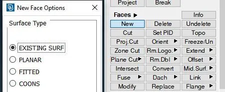
There are four options in the 'New' option, so we can use them appropriate to add new face over there ( at single cone). 'Fill Hole' option is used to fill the holes or fill the gaps or cracks.
Here, below I have shown single cons on surface and they are resolved by adding new surface and single cons can be converted into double cons.-
- Below we can see single cons so we can add surface by projecting hot points over the single cons which is present above the surface.
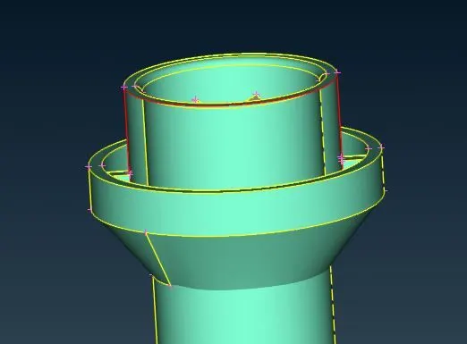
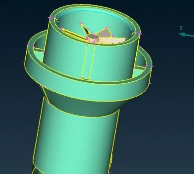
It is fixed by adding a new surface (Faces> New > Coons).
- This single cons can be fixed by doing delete this surface first and then create a new surface over there.
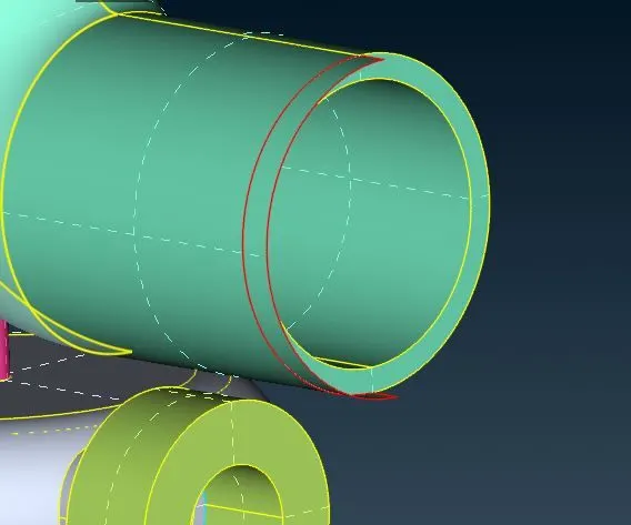
It is fixed by adding a new surface (Faces> New > Coons).
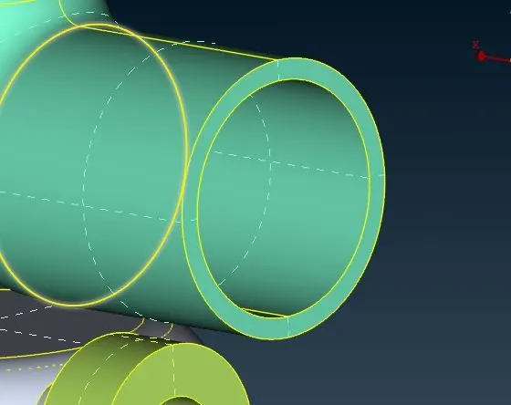
- Here we can see that two surfaces are penetrating and they create the single cons.
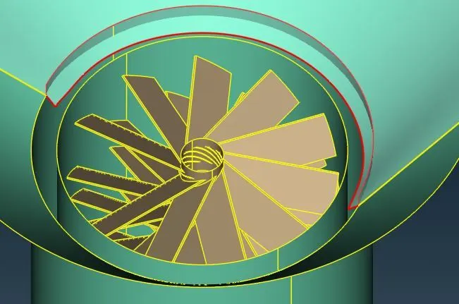
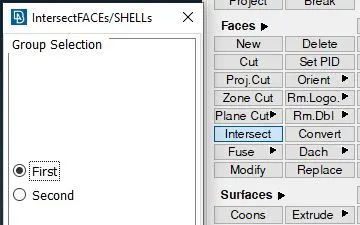
It can be resolved by intersection command in Faces. In this command we need to select two faces and they get separated and we can delete those extra surface.
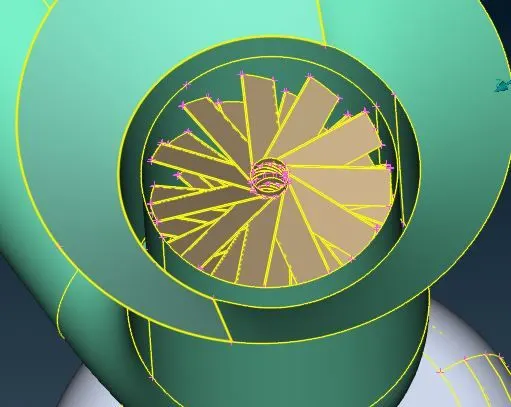
- Here it is the single which is present. So we need to fix that by adding some hot points over there which is shown below.
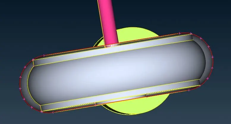
It is fixed by adding a new surface (Faces> New > Coons).
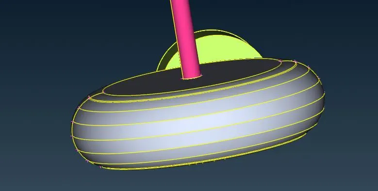
Till now we have fixed single cons present in the geometry. But in the geometry There are so many overlapped surface and triple cons present which need to be removed.
- It is getting removed by just deleting the surface.
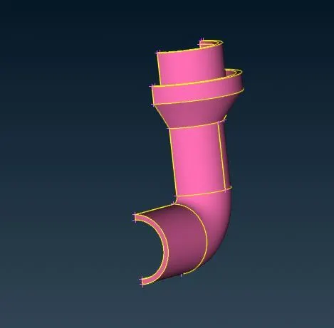
- It is getting removed by projecting that lower cons on the shaft and gets deleted.
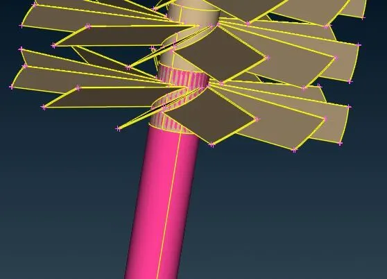
- It is getting removed by just deleting the surface. There has to be two surface deleted and makes a hollow shaft that is how we are getting double cons over there.
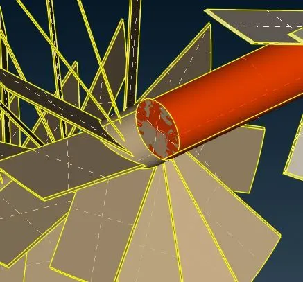
- It is getting removed by just deleting the surface.
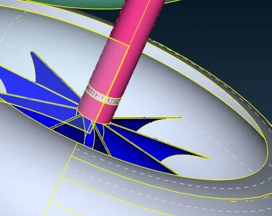
- It is getting removed by projecting those both the cons on the shaft and gets deleted.
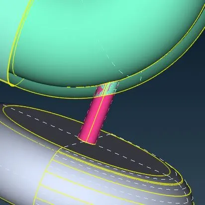
- It is getting removed by projecting that cons on the blade. There are two surface get deleted to make a hollow shaft (First surface is surface of shaft and another one is adjacent surface of that surface of shaft).
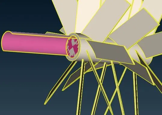
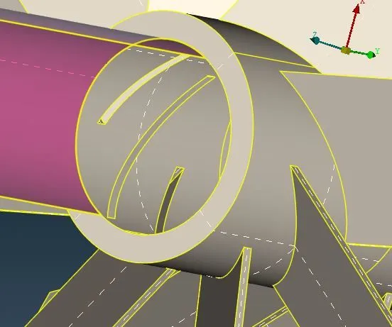
- It is getting removed by just deleting the surface. There has to be two surface deleted and makes a hollow shaft that is how we are getting double cons over there.
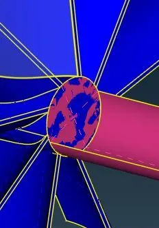
- Here we can see triple cons are present in the geometry which means there are multiple surfaces but we need double cons there so we need to delete the surface between two blades to make the shaft hollow
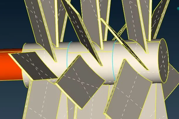
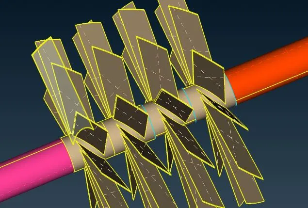
After geometry clean up the geometry looks like shown below.
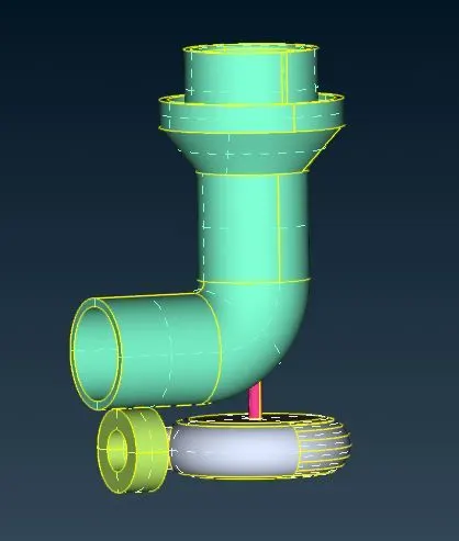
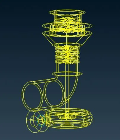
As we can see the geometry in the wire mode, there is no single cons present. But as we can see in the second image there is one triple cons formed. It is not error. We need the triple cons over there, it is necessary. So the geometry has been cleaned up.
iv. Geometry check up -
This step is done to check the if there are any error in the geometry like needle face, cracks etc.
Toolbar > Check > Geometry . Select the geometry and click on result. We can see green tick over there which means geometry has no error.
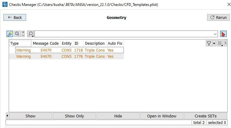
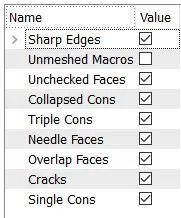
Here is the types of the errors .
As we can see there is one triple cons formed so we get only warning as shown in image below.
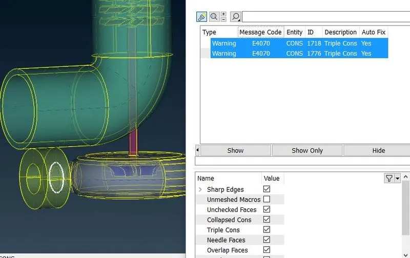
As we know triple cone is necessary here in the particular case. So we can proceed the geometry as it is perfect and cleaned up and checked up.
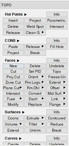
TOPO Deck -
v. Assigning the PID
To assign the PID we need to close the geometry from the open ends.
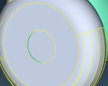
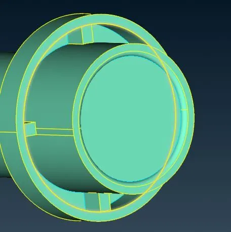
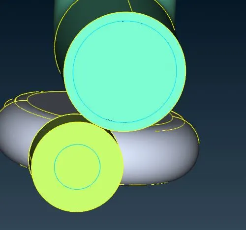
Create the PID in the properties (Toolbar > Properties).
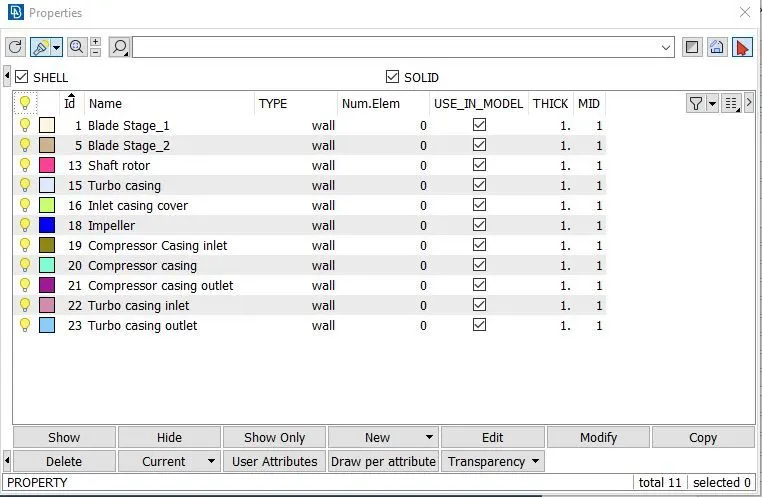
After creating the PID, in PID mode for geometry , apply the PID by doing (right click on the particular PID > Apply > click on the particular face) and do middle click.
Blade_stage_1 -
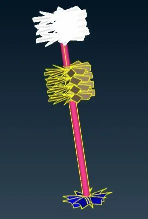
Blade_stage_2 -
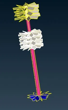
Shaft rotor -
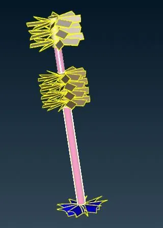
Turbo casing -
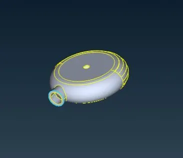
Inlet casing cover -
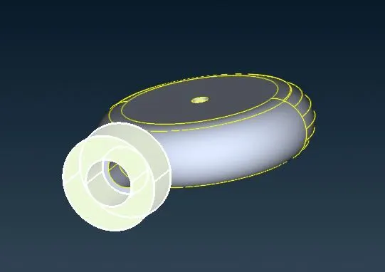
Impeller -
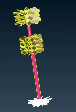
Compressor casing inlet -
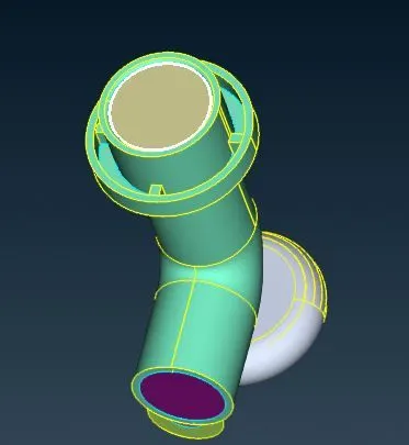
Compressor casing -
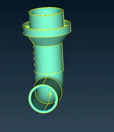
Compressor casing outlet -
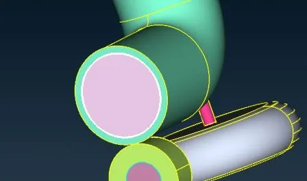
Turbo casing inlet -
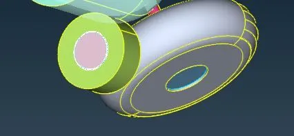
Turbo casing outlet -
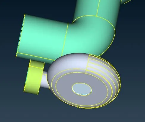
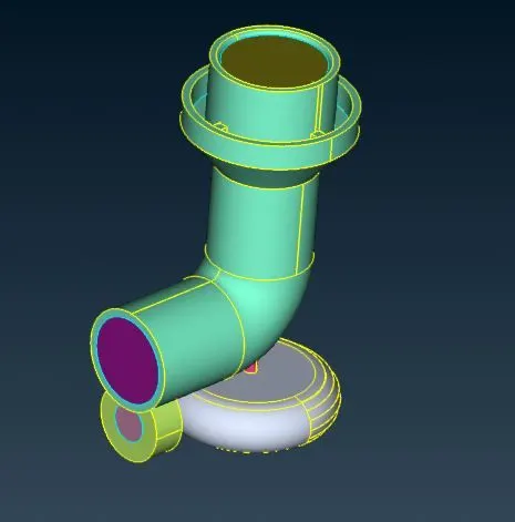
After applying all the PID, PID geometry looks like as shown below,
vi. Defining the element size -
To define the size element click on the Classic Mesh deck.
Classic Mesh -
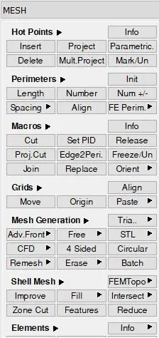
Perimeters > Lenght and we can see two types. a) Perimeters b) Macros .
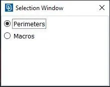
Perimeters > Length > Perimeters. Select the geometry and Apply lenght
Perimeters > Length > Macros . Select the geometry and Apply lenght
After setting the lenght , Click on the Mesh parameters. Apply Target length and type of the mesh = Tria. Then apply mesh quality accordingaly.
Here Target lengths for different surface of the geometry are different shown below,
- Blade stage-1 = 1 mm
- Blade stage-2 = 1 mm
- Impeller = 2 mm
- Shaft rotor = 1 mm
- Turbo casing = 5 mm
- Compressor casing = 5 mm
- Inlet casing cover = 5 mm
vii. Generate surface mesh.
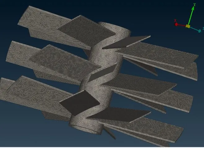
To deploy the mesh ( Mesh Generation > CFD > visible).
- Blade_stage_1 - Target length = 1 mm
- Blade_stage_2 - Target length = 1 mm
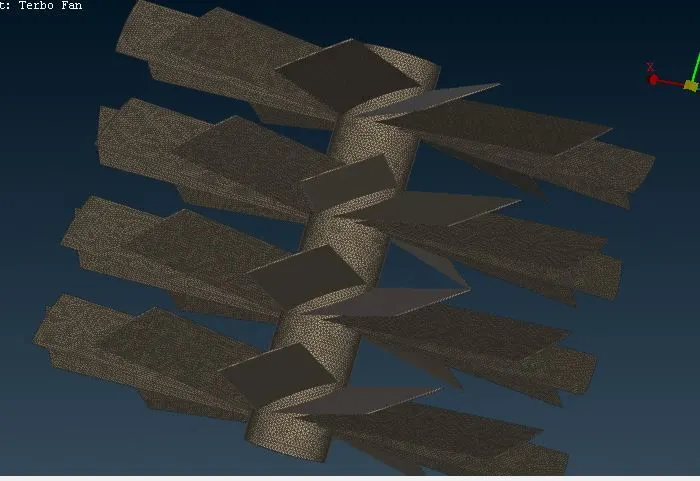
- Impeller - Target length = 2 mm
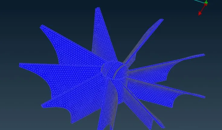
- Shaft rotor - Target length = 1 mm
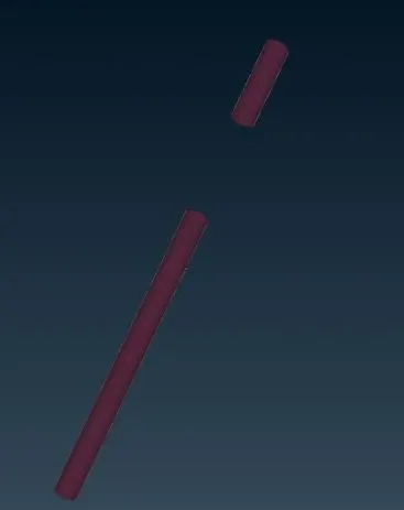
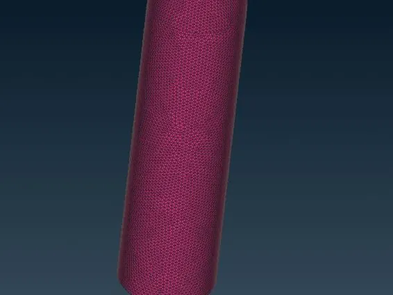
- Turbo casing - Target length = 5 mm
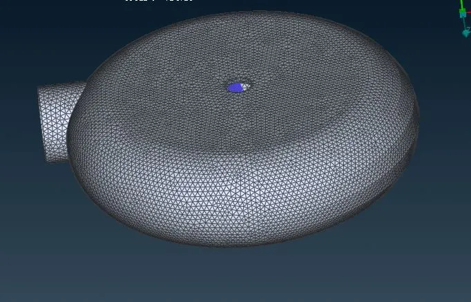
- Compressor casing - Target length = 5 mm
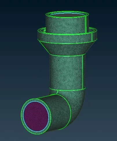
- Inlet casing cover - Target length = 5 mm
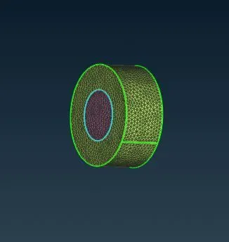
The surafce meshed geometry looks like shown below
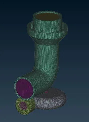
There are two intersection surface in the geometry as shoen below.
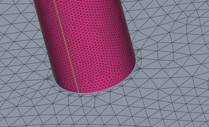
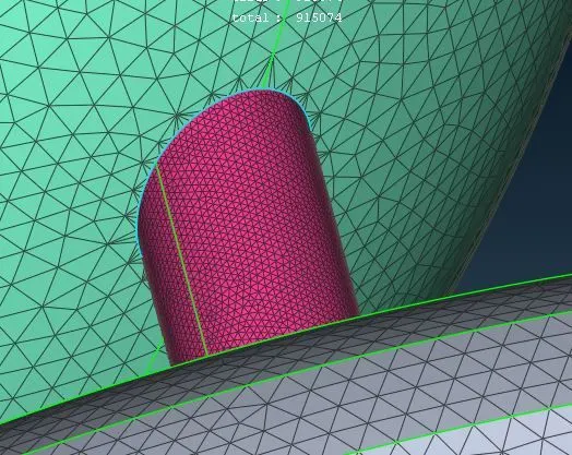
ANSA gives the mesh at those locations like these shown above images. Because target length of the shaft rotor is 1 mm and for compressor casing is 5 mm so mesh elements get became 1 mm to 5 mm at the intersection.
viii. Generate CFD volume mesh.
To generate the volume mesh first we need to define the volumes where volumetric mesh will be present (Classic mesh > Volumes > Define).
To generate the volumetric mesh surface mesh is required. After surface mesh click on the 'Define' and select option 'whole db' in Detect on and click 'OK'
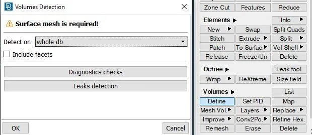
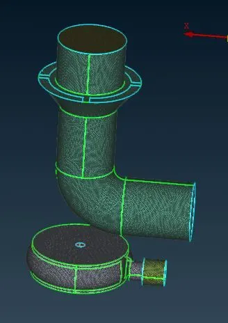
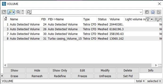
After clicking ok we can see the window which shown below. ANSA detects the volume where volumetric elements should be present. We delete the unnecessary detected volume where we do not wanna mesh. We only keep the required volume where we want mesh
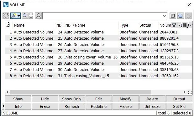
These are required volumes.
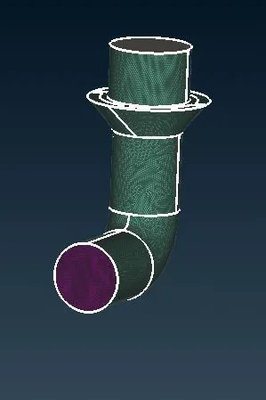
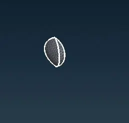
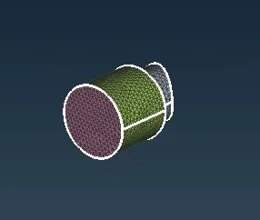
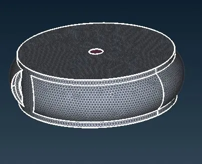
After deleting all unnecessary volumes we have the geometry looks like shown below
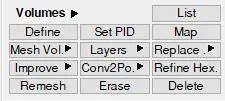
To generate the Volumetric mesh we need to follow the step (Volumes > Mesh Volume > Tetra CFD) in the classic mesh
By following above steps for each and every detected volumes we get the Volumetric CFD mesh for the volumes shown below
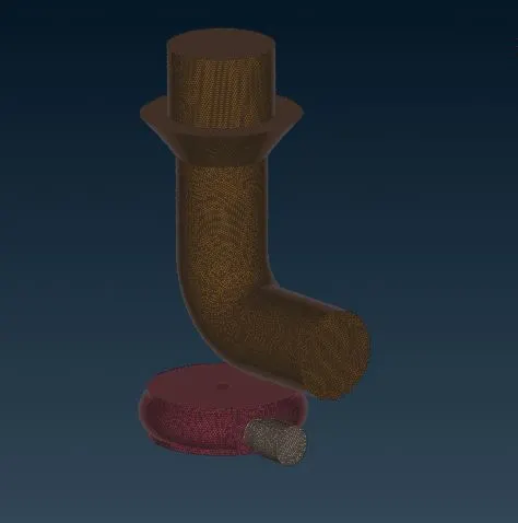
Tetra CFD volume mesh has been craeted for all the required volumes
Here we can see how volumetric tetra CFD elements look like
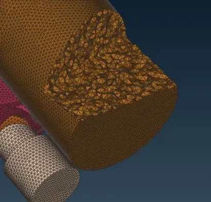
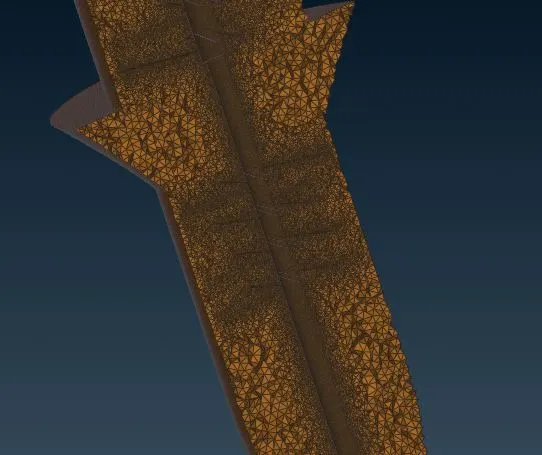
No of terta elements = 6955902
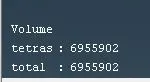
Conclusion -
We have generated volumetric (Tetra CFD) mesh for turbocharger. We have to clean the geometry first, like operation on single cons and triple cons and adding new surfaces.
If we want to generate 3D mesh / Volumetric mesh we need to do suraface mesh first and then we can proceed for 3D mesh. To generate volumetric mesh surface mesh is required.
There are different target lengths for different surface of the geometry. after surface meshing define the volumes where we want volume mesh and apply tetra CFD mesh over those volumes.