Week 3 Challenge : CFD meshing on Turbocharger
- Aim :
For the given model of the turbocharger, check for the geometrical error to make appropriate volumes. Create and assign PIDs accordingly. Create surface mesh and use that to create a volumetric mesh.
- Turbocharger Model :
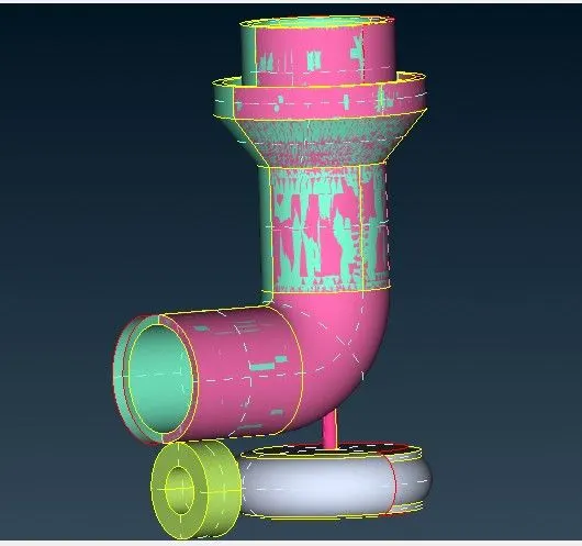
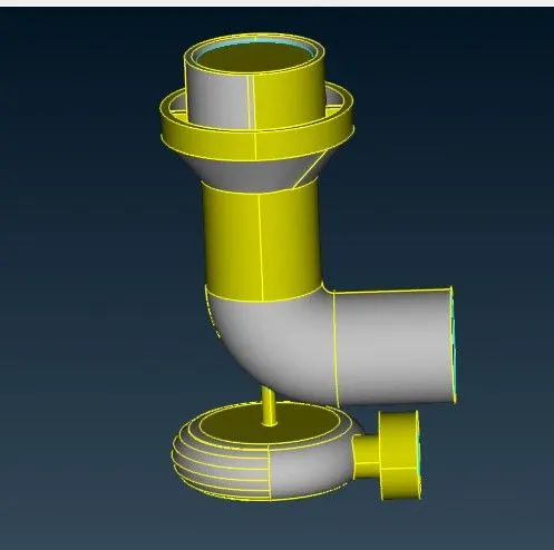
Initial model and final geometry cleaned model
- Procedure :
A. Topo/geometry clean-up :
1.. Upload the ANSA file using the open option under file drop down.
2. Start with the topo clean by doing geometry check to find single and triple cons in the geometry. select topo under faces and box select the entire model so that any missing cons can be detected and the geometry clean up can done more accuractely.
3. Delete the unnecessary overlapping surfaces by using the PID region .
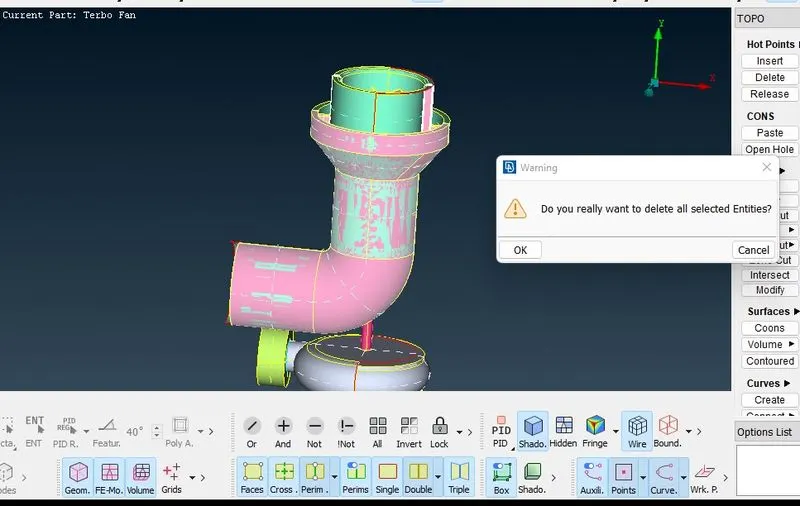
4. Start with fill the surface and clearing the single cons by creating surfaces where ever required.
5. Creatain area created by using the new option under faces don't satisfy the surfaces we require, therefore, certain hotspot are projected so that small surfaces can be created and later can be joined and get the required geometry.
6. Use intersect option to delete the surface which has no separate entity, therefore a separate entity is formed when using intersect and can be deleted easily.
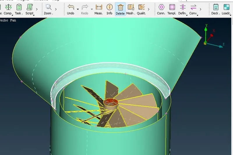
7. Once the single cons are solved far, we can focus now on solving for triple cons which are present at the shaft region, since we need to have a single volume which makes it easier to mesh in the later stage. Delete the overlapping surfaces to reduce them to double cons.
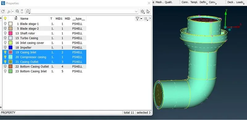
8. After the unnecessary triple cons are removed, we can now start noming each part by assigning them an individual PID. After naming them, we can now move ahead with surface meshing.
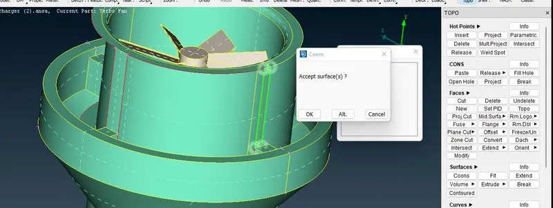
Create small suraces after assigning hot points
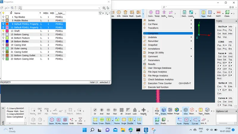
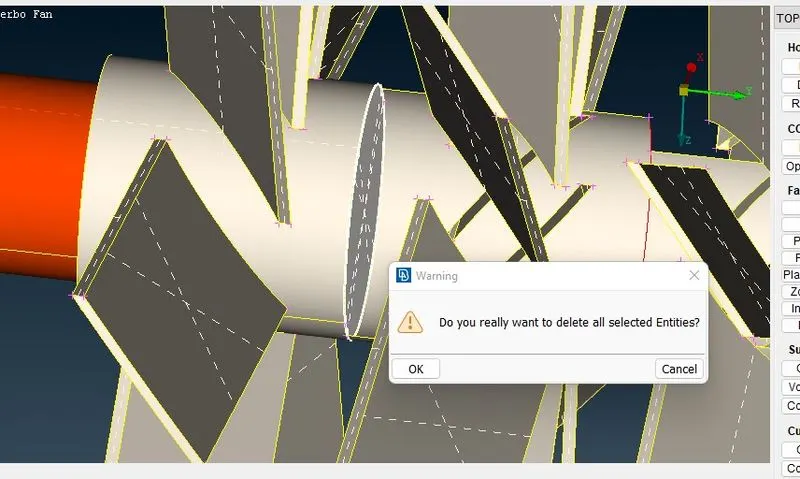
Delete Unnecessary Hot points, PID's and surfaces
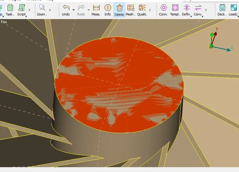
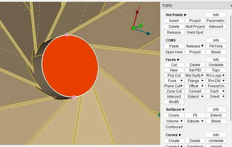
Release TOPO
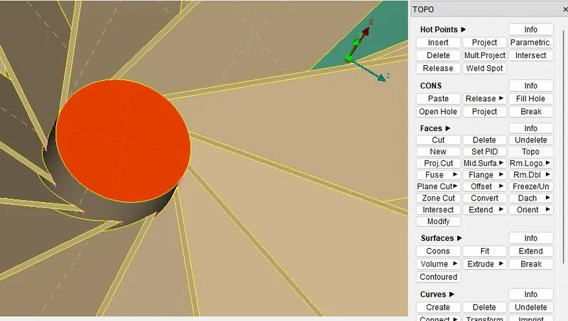
Release CONS
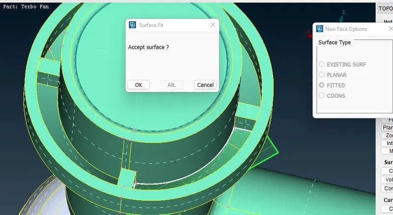
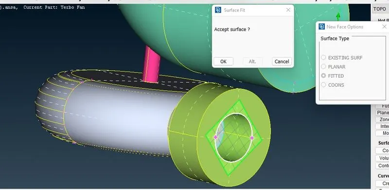
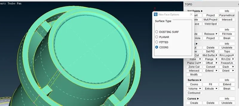
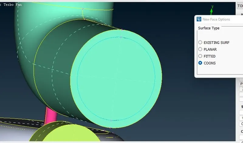
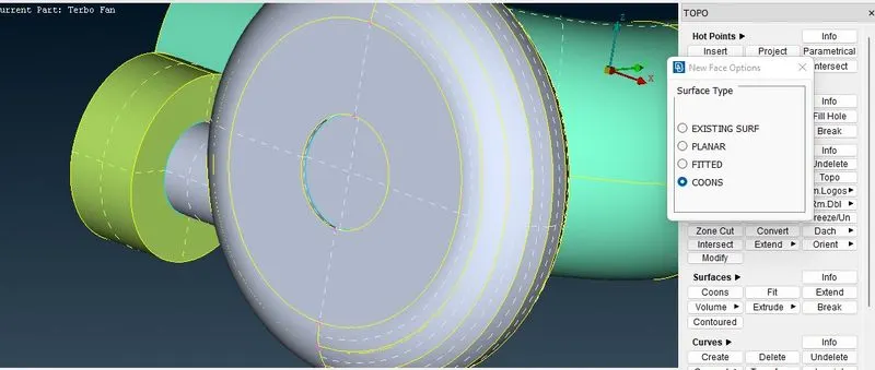
9. Before moving to the meshing , i am going to close the open surfaces of the model so that we can able to do simulation.
B. Surface Meshing :
1. We need to mesh each components as per the given criteria in the question, therefore we need to mesh individually.
Compressor Mesh
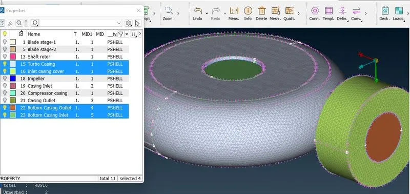
Turbo Mesh
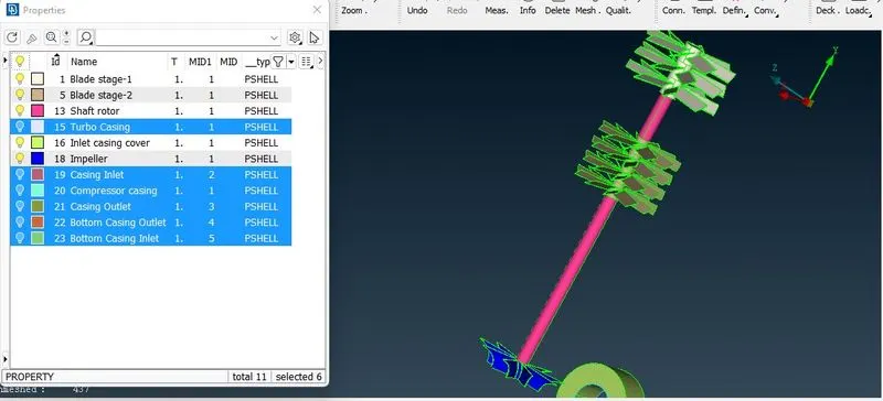
Impeller,Shaft rotor, Blade stage-1 & Blade stage -2 Meshing
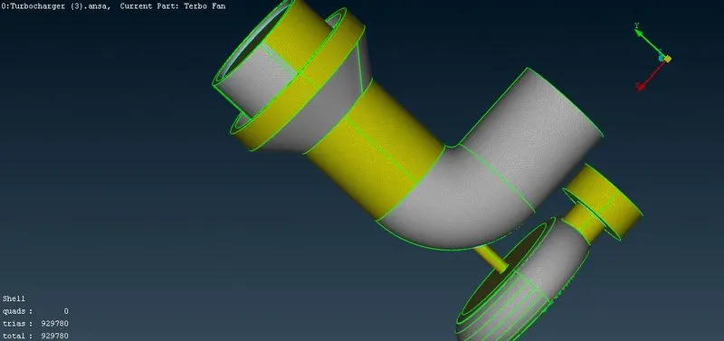
Final Mesh
2. Enter the quality and mesh parameters and length of the mesh accordingly for each component.
3. While entering the mesh length, be aware of the change in mesh length between components with different mesh length, when they come in contact they tend to erase the other mesh, therefore while entering the perimeter and macros we need to give a range ranging from the bigger to smaller mesh length to avoid the mesh to get erased.
4. After the mesh is generated, we can create a boundary of the varying mesh length and maintain a constant mesh length on the other side of the boundary.
C. Volume meshing :
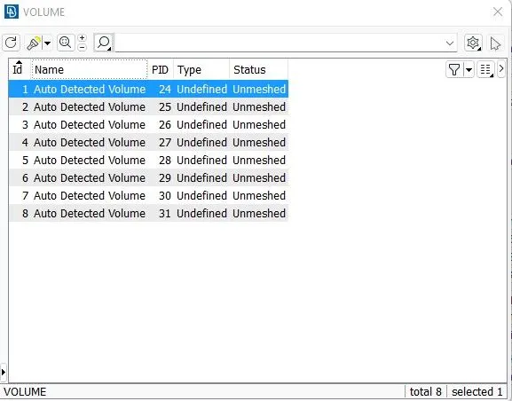
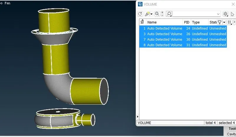
1, Auto Detected Volume, 24, Undefined, Unmeshed -- Inside volume of our compressor casing .This volume is responsible for accumulating the fluid to flow.
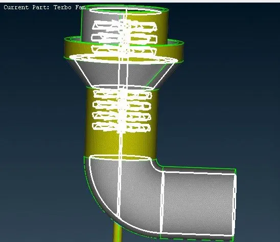
2, Auto Detected Volume, 25, Undefined, Unmeshed -- This is parent geometry with thickness so whatever material we are using to creating this casing so that material have this thickness.
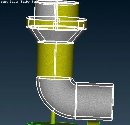
3, Auto Detected Volume, 26, Undefined, Unmeshed -- The volume in which fluid will flow
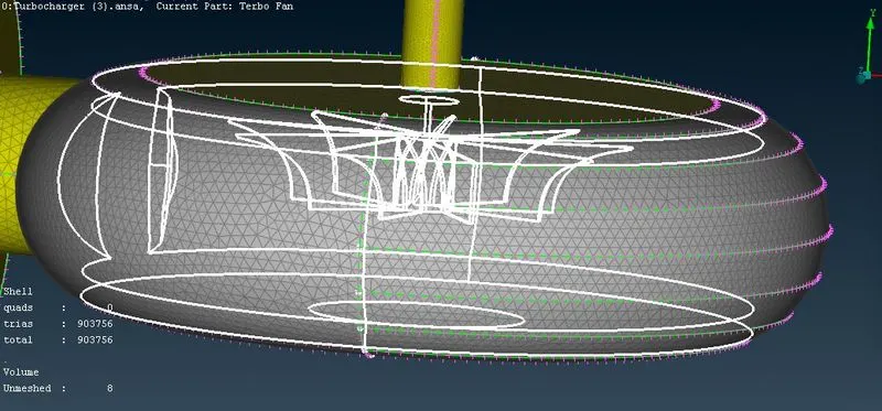
4, Auto Detected Volume, 27, Undefined, Unmeshed -- The thickness of turbo model.
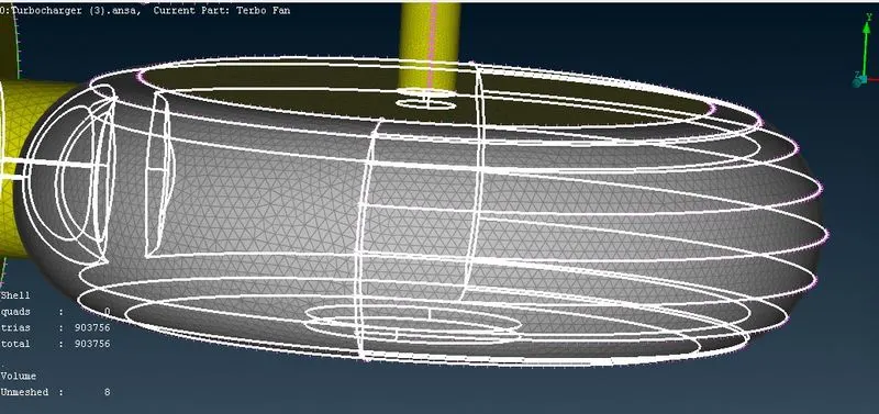
5, Auto Detected Volume, 28, Undefined, Unmeshed -- Thickness of inlet casing pipe.
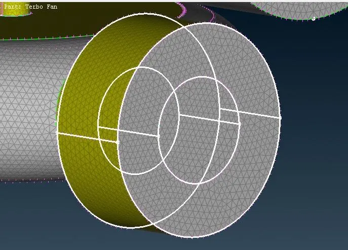
6, Auto Detected Volume, 29, Undefined, Unmeshed - Thickness of blade 1 , blade 2 , rotor-shaft and impeller
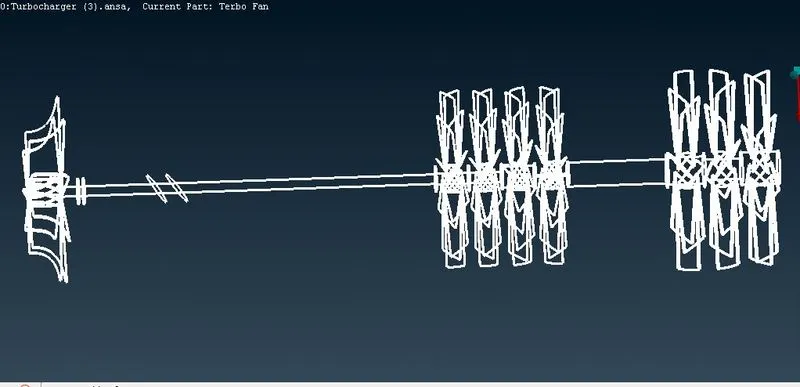
7, Auto Detected Volume, 30, Undefined, Unmeshed-- The volume where the fluid may flow
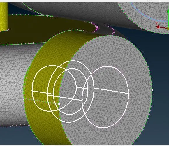
8, Auto Detected Volume, 31, Undefined, Unmeshed-- The volume of inlet casing pipe
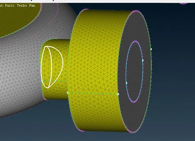
1. After the surface meshing is done, we can now achieve volume meshing.
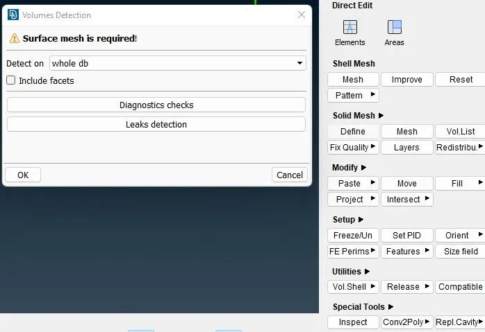
So, let's deleting the unnecessary parts or the thickness of our parent geometry
2. Under Volume meshing, choose define and select whole db in the pop up window.
Right click on particular part --> Remesh --> Tetra CFD
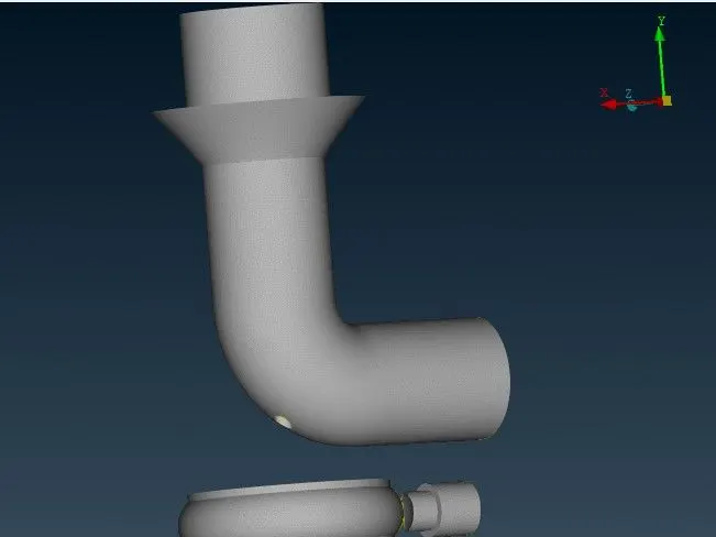
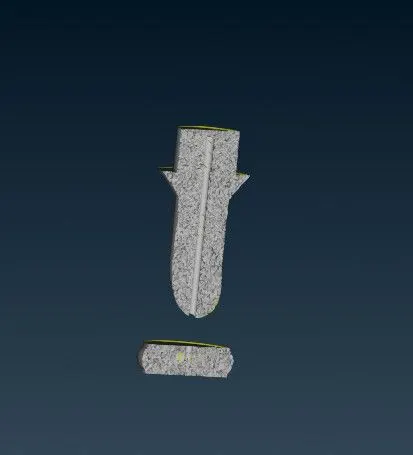
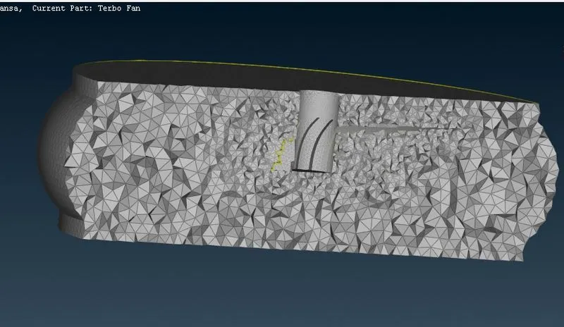
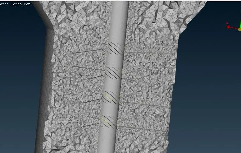
Completed model with volume mesh drive :
https://drive.google.com/file/d/12ScRhlD6ggKi_cECGtSmzZLHpIZnPPSD/view?usp=sharing
- Learning outcomes :
1. Checking for geometry errors and correcting the geometry using different geometry editing tools.
2. Deleting overlapping regions to improve mesh quality and avoid errors while volume meshing.
3. Correcting the triple cons and single cons accordingly as per the geometry requirements.
4. Using fine under auxileries helps in giving a finer surface finish at the connecting region.
5. Creating surface mesh individually and also maintaining mesh length range at the contact region between 2 different mesh lengths.
6. Identifying and creating volume mesh only for the fluid region part.
7. Tools to create volume mesh.
- Results :
1. Completed geometry clean-up with all the inlets and outlets closed to create a closed volume.
2. Surface Meshing achieved with different mesh lengths as per the question:
3. Volume mesh created for the fluid volume region along with cut sections to view the 3D mesh :
- Conclusions :
1. Achieved volumetric mesh of the turbocharger model.
2. Different mesh length size tends to give errors at the contact region of 2 different mesh length regions, therefore mesh ranges can be given to avoid erasing of mesh.
3. Volumetric mesh can be achieved only after creating surface mesh successfully, or else the geometry can give fatal errors while volume meshing.
4. Overlapping surface can be deleted using the universal delete option.
5. Unnecessary single and triple cone can be removed and editted using different tools such as cons project, topo, release and fine tools while geometry clean up.
6. Successfull volumetric mesh can be achieved only after correct geometric clean up and surface mesh.