Week 3 Challenge : CFD meshing on Turbocharger
CFD Meshing on Turbocharger
Aim/Objectives:
- To check geometrical errors
- To perform topology cleanup to remove errors in the geometry
- To assign PIDs
- To apply surface mesh of tria elements with provided target lengths for each component
- To deploy CFD mesh
- To analyze results of CFD meshing
Procedure:
A) To check for the geometrical errors and perform Topology cleanup
- Import the model or double click on given file to open it
- Select PID in Draw mode (At bottom toolbar)
- Click on tools (at the top toolbar) and select checks and then select geometry check
- Execute geometry checks on ‘visible’ and tick ‘single cons’ so as to check presence of single cons as well along with all other checks which are already ticked by default
- Errors in geometry indicate that there are many triple and single cons present in geometry of model and model is open from various places. So in order to make model closed we must fill holes by creating new surfaces wherever required and should close the model geometry.
- To make the process simpler we can disable shadow mode and enable wire mode whenever required, similarly we can enable or disable double cons.
- We can create new faces or can use fill hole (under cons) to create missing surfaces. To fill some holes on compressor casing and turbo casing, creating/projecting the hot points is necessary. After creating/projecting hot points, we can use ‘New’ option to create surface and check for alternates of surface possible. Choose correct and desired alternative.
- There are also overlapped surfaces at many places. Overlapping of surfaces can be identified using glitching seen on the surface. Overlapped surfaces should be removed wisely (Use of cross hedges is very important and selecting surface as entity instead of whole PID is also necessary). Boolean operation, especially ‘NOT’ operation is very useful in finding all intersection and overlapped surfaces.
- Extended surface can also be seen in geometry and it can be deleted by cutting the face using projection of con on the surface.
- Also there is intersection of two surfaces present on compressor casing. Intersection of two surfaces can be identified by presence of single con having multiple surfaces attached to it. Using ‘Intersect’ too under ‘Faces’ in Topo Deck, we can intersect the surfaces and delete intersected part/extended surfaces. (We need to provide two different surfaces after selecting the ‘intersect’ option.
- ‘Release’ and ‘Topo’ options under ‘Cons’ can be used to solve single and triple cons when creating or deleting surfaces doesn’t solve the cons.
- If we perform ‘topo’ on entire geometry we can see many triple cons present especially on inside components. Even though surfaces forming triple cons are material part of geometry we can delete some of them to make whole internal assembly as one volume since it will be useful in volumetric meshing. (As our aim is to focus on fluid domain, all material thickness can be considered as single volume.
B) Surface Meshing (2D)
- Before meshing we should assign PID in order to make each part of turbocharger model accessible easily
- To assign PID we should click on ‘properties manager’ option from toolbar then right click and follow ‘New’ PShell PShell to create new PID such as compressor casing outlet, compressor casing inlet, turbo casing inlet and turbo casing outlet. By doing right click on each PID name we can see apply option to assign PID. Similarly we can assign PID to already created PIDs.
- Once PID is assigned to all parts we can start meshing process.
- Firstly we should set minimum and maximum lengths as per target mesh length. To do that, click on quality criterion option and fill the values of min. and max. length and then click on ‘apply’, ‘ok’.
- Now click on Mesh parameters and select mesh type as ‘Tria’. Also input the targeted length.
- Select length in mesh deck and provide input of target mesh length in parameter as well as macros for each surface/PID
- Finally click on spot mesh in mesh generation and select surface/PID where we want to generate the mesh
- We can see that mesh has been generated over all surfaces except for those where some con is common for different mesh lengths. In such cases we can mesh surface again by providing quality criterions and mesh parameters as expected. We only need to leave ‘macros’ as default value (range of mesh length) so that mesh of range of length is created. Now we can see transition happening towards common cons.
C) Volumetric Meshing (3D)
- Click on volumetric mesh deck.
- Click on define. Now ensure that ‘whole db (database)’ is selected for auto detection. Click ok.
- Now ANSA will detect all closed volumes. Since we only need to concentrate on fluid flow, we can delete all other volumes where flow is not possible, i.e. volumes of thickness of materials of model components.
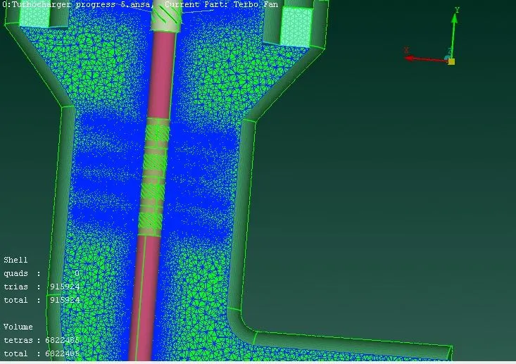
- Choose CFD mesh for all volumes before generating mesh. Once mesh is generated, we can see and confirm it by taking cut section. To do that choose cut plane from upper tool bar, click ‘New’, choose appropriate plane. Select centre point of surface where you want to have cut section and then model browser window opens. Select new to create new part. Now double click on new part and click ok on new window that opens up. We can see generated mesh in the cut section.
Learning outcomes:
- I have learnt how to do geometrical errors check in ANSA. I have also learnt about different errors that I might get as an output of the ‘checks’. I have explored how these errors can be eliminated by doing topology cleanup.
- I have learnt how to create and assign PID.
- I have learnt how mesh length affects quality of mesh(discussed in detail in conclusion part).
- I have learnt how to deploy volumetric mesh (CFD Tria) to a given model
Results:
Following is the link of meshed model
https://drive.google.com/file/d/1j2HCPi9QKE2cZD4nkdUGimeeeXoZZs1s/view?usp=share_link
Conclusion:
- We can see different mesh lengths at different surfaces and transition area on the surfaces in ‘mesh deck’
- Volumetric mesh of CFD Tria element type is deployed on the model.
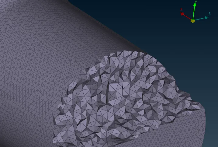
- In ‘volumetric mesh deck’ we can see quality of mesh created by taking cut section of model. Here also we can see transition and effect of mesh parameters on element size.