Week 2 Challenge : Surface meshing on a Pressure valve
Surface meshing of pressure valve
Aim/Objectives:
- To check geometrical errors in given pressure valve model
- To perform topology cleanup to remove errors in the geometry
- To mesh the model for 3 different target lengths (1mm, 3mm, 5mm) and ‘tria’ element type
- To compare results of all three cases and chose the best result
Procedure:
A) To check for the geometrical errors and perform Topology cleanup
i) Import the model or double click on given file to open it
ii) Select PID in Draw mode (At bottom toolbar)
iii) Click on tools (at the top toolbar) and select checks and then select geometry checks
iv) Execute geometry checks on ‘visible’ and tick ‘single cons’ so as to check presence of single cons as well along with all other checks which are ticked by default
v) Examples of errors shown after geometry checks are as follows
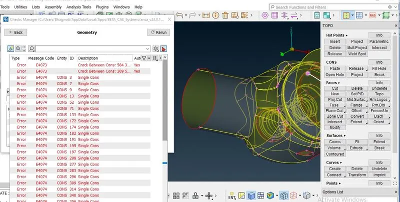
vi) Errors in geometry indicate that there are many holes and single cons present in geometry of model and CFD applications always need closed model. So in order to make model closed we must fill holes by creating new surfaces wherever required and should close the model geometry.
vii) To make the process simpler we can disable shadow mode and enable wire mode whenever required, similarly we can enable or disable double cons.
viii) We can create new faces or can use fill hole (under cons) to create missing surfaces
ix) When we create new face at bottom of pressure valve we can see triple con being created on the model
x) We can again check for geometrical errors and following is the result that we get
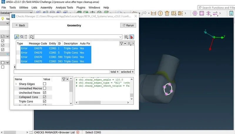
xi) As triple con formed can be neglected as error here we can confirm that topology cleanup is done.
B) Meshing
i) Before meshing we should assign PID in order to make each part of pressure valve model accessible easily (PID assigning is not necessarily required if target length of mesh is same for all parts)
ii) To assign PID we should click on ‘properties manager’ option from toolbar then right click and follow ‘New’ PShell PShell to create new PID such as outlet, inlet, body, spring, column, valve head, etc and then by doing right click on each PID name we can see apply option to assign PID. We can make use of various Boolean options as and when required to select different surfaces for assigning PID. Also we can make use of PID region or ‘Ent’ option to select proper surfaces
iii) Once PID is assigned to all parts we can start meshing process.
iv) Firstly we should set minimum and maximum lengths as per target mesh length. To do that, click on quality criterion option and fill the values of min. and max. length and then click on ‘apply’, ‘ok’.
v) Now click on Mesh parameters and select mesh type as ‘Tria’. Also input the targeted length.
vi) Select length in mesh deck and provide input of target mesh length in parameter as well as macros for each surface/PID(even we can select whole pressure valve if target length is same for all components)
vii) Finally click on spot mesh in mesh generation and select surface/PID where we want to generate the mesh
CASE I: For 5mm mesh length, target length should be 5mm (in mesh parameters, macros and parameter length) and min. and max. length are provided as 3mm and 7mm resp. in quality criterions.
CASE II: Similarly provide 3mm at all 3 target length options and provide min. and max. length as 1mm and 5mm resp.
CASE III Similarly for 1 mm target length, min. and max. length should be 0.5mm and 2mm resp. Here also target length should be selected for all 3 options.
Learning outcomes:
i) I have learnt how to do geometrical errors check in ANSA. I have also learnt about different errors that I might get as an output of the ‘checks’. I have explored how these errors can be eliminated to do topology cleanup.
ii) I have learnt how to create and assign PID. I have also learnt use of different Boolean options of ANSA
iii) I have learnt how mesh length affects quality of mesh(discussed in detail in conclusion part)
Results:
I have attached result of all 3 cases
(Link for .rar file: https://drive.google.com/file/d/19Xf9MCI6JIwhNtnoIT97t6CPm9H9Cf4p/view?usp=share_link)
Conclusion:
i) As we decrease mesh length, mesh becomes more fine(mesh quality improves), therefore 1mm mesh length gives best quality of mesh in the results.
ii) As we decrease mesh length number of nodes/mesh elements increase (this will result in more computational time in solver) and it results in larger file size(for 1mm mesh length my .ansa file is more than 20MB)
iii) When targeted mesh length is larger than any dimension of specific surface then element size will be larger and element will not fit on that surface (very bad quality of mesh)
iv) When a model has considerable difference in dimensions of different components then it is better to use different mesh lengths for different components to have a optimum solution.