Week 3 Challenge : CFD meshing on Turbocharger
EPORT
CFD Meshing on Turbocharger
THEORY
Turbocharger
In an IC Engine, a turbocharger (often called a turbo) is a forced induction device that is powered by the flow of exhaust gasses. It uses this energy to compress the intake gas, forcing more air into the engine in order to produce more powder for a given displacement.
Like other forced induction devices, a compressor in the turbocharger pressurizes the intake air before it enters the inlet manifold. In the case of a turbocharger, the compressor is powered by the kinetic energy of the engine’s exhaust gases, which is extracted by the turbocharger’s turbine.
The main components of the turbocharger are:
- Turbine – usually a radial turbine design
- Compressor – usually a centrifugal compressor
- Center housing hub rotating assembly
Application
Turbochargers have been used in the following applications:
- Petrol-powered car engines
- Diesel-powered car engines
- Motorcycle engines
- Diesel-powered truck engines
- Aircraft piston engines
- Marine engines
- Locomotive and diesel multiple unit engines for trains
- Stationary/industrial engines
- MODEL
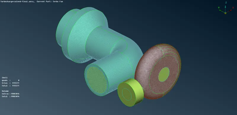
Surface meshing is performed with the given target lengths as per PIDs.
- Blade stage-1 = 1 mm
- Blade stage-2 = 1 mm
- Impeller = 2 mm
- Shaft rotor = 1mm
- Turbo casing = 5 mm
- Compressor casing = 5 mm
- Inlet casing cover = 5 mm
PROCEDURE
GEOMETRY CLEAN-UP
- When reading geometry in ANSA one should first check the topology.
- Switch to PID colour view mode. This displays the faces coloured according to their Property ID.
- Before one starts cleaning up the geometry of the model it is useful to perform a number of checks that are incorporated in ANSA. ANSA can identify and isolate on the screen the problematic areas that require the user’s attention. Check to locate geometrical problems of the model such as Unchecked Faces, Collapsed Cons, Triple Cons, Needle Faces, Overlap Faces, Cracks, and Single Cons. A number of errors are shown by the check manager, it is required to clean up the geometry before stepping up for meshing. These errors are shown in the geometry with highlighted red lines. The errors found on the model can be visualized by selecting the appropriate option from the focus toolbar. The FOCUS group contains all the functions that are used to isolate and control the visibility of selected entities in order to obtain a clear image of the working area of the model.
Area Selection Mode
- ENT: selection of individual entities; one by one.
- PID: selection of all the entities of one selected PID.
- PID Region: selection of the entities of an unconnected region of one PID.
- LOOP: Automatic selection of closed loops of edges/ CONS etc (useful for hole closure)
TOPO Deck
- To patch the problematic surfaces, choose a new face from the TOPO deck. Choose the surface type according to the surface shape required to be formed.
- Fill holes in the CONS section can also be used to patch a surface. It can be used for multiple patches at once.
- Inserting and projecting hot points are also used for complicated sections to be patched. Using hot points smaller less complicated geometry shape is created so that fitted faces can be used.
Creating new PIDs
PID function
- Select with the left mouse button the small triangular Face from its crosshatch. Confirm with the middle mouse button. The Properties window appears, so one can select the PID one wants to assign to the selected face. One can now view the faces coloured according to their Property ID.
- For this model, a number of PIDs are created Blade Stage_1, Blade Stage_2, Shaft Rotor, Turbo Casing, Inlet Casing Cover, Impeller, Casing Inlet, Compressor Casing, Casing Outlet, Bottom Casing Inlet, and Bottom Casing Outlet.
- Now assign mesh length and mesh each component one by one by considering one PID separated in the screen.
Shell Mesh
- Switch to the MESH menu. In the MESH menu, the Faces are now Macros Areas and the CONS are Perimeter Segments. The hot points are displayed as white dots.
- First, assign the mesh length. Mesh lengths are chosen according to the size of PIDs in order to attain the best possible mesh result.
- To assign mesh length make sure the value input will be done in four places. Firstly, in the Perimeter Module buttons, the inside length gives the desired mesh value in Perimeter and Macro respectively. Then, in Mesh Parameter and Quality Criteria, here we also have to insert values for maximum and minimum target length and also mention element type in the Mesh parameter section.
Volumetric Mesh
- The ANSA batch meshing manager is a powerful tool for versatile, controllable and predictable high-quality meshing with shell (surface, CFD, wrapping of 3D parts), or volume (solid components, CFD, HEXA interior) elements.
- Having first created the boundary layer elements, consider the definition of the Volume entities. This can be easily done with the function Volumes>Define [Auto Detect].
- All the Volumes defined manually or detected by ANSA are listed in the Volumes>List window.
- Check this list to monitor the type, Name, PID and status of the Volumes.
- One can always manage the Volumes in the model using the Volumes>List window, edit the volume, and delete the PID showing outer structure of the model.
LEARNING OUTCOMES
Error Faced
Collapsed cons
- Check geometry option showed four collapsed cons attached to compressor casing triple cons. It is fixed it using the fix option shown in the check geometry box after right-clicking on the error shown.
- The other procedure can also be used to manually release them, delete the extra hot points, use BREAK, and then TOPO.