Week 2 Challenge : Surface meshing on a Pressure valve
AIM: 1) To check for the geometrical errors and perform Topology cleanup.
2) Set three different target lengths as three different cases and mesh the model.
PROCEDURE:
TOPOLOGY CLEAN UP
- Topology clean up is basically used to check the geometry whether it is perfect to carry out the meshing process.
- We use 'Geometry check' option to carry out the topology clean up. It can be accessed from the top menu.
- Some checks that are present in ANSA are: Single con check, cracks check, overlap check, Triple cons check.
- We use 'Execute' command under Geometry check option to perform the basic topology check.
- After giving the execute command and if we find out that single cons are present basically we need to eradicate them.
- Single cons are represented in red lines.
- A single con indicates that there is no surface shared with them.
- Another way to Check single con is by turning off all the other options and enabling only the single con option in the menu.
- By pressing 'CTRL+SHIFT' and going to wire frame mode also we can get a clear picture of the single cons.
FACE SECTION
- By clicking 'New' option in the face section we can create a new surface.
- There are basically four surface type. They are Existing surface, Planar, Coons and fitted.
- Existing surface option is used to fill a hole present on a existing surface by selecting the cons
- Planar option also works on the same principle as Existing surface option.
- Coons is used to fill a hole on a existing surface.
- LOOP is a special tool which is basically enabled to select all the cons present in the loop instead of selecting them one by one.
- A hole can be filled by using Fill hole option under the 'Cons Section' by selecting the hole or entering the hole diameter.
- To select a con in the wire frame mode we need to click the con 'Two times'.
Creation Of PID
- We can create a PID by, right clicking ----> New ---> Pshell ---> Assigning the desired name.
- We can change the colour of PID by double clicking the colour option.
- PID region is used to select the surfaces that are in contact.
- The lock option is used to bring the model that was visible when enabling the option
- Pick option in the PID menu is used to check where the PID is present in the surface or geometry.
- If the bulb symbol is partially turned on only half of the geometry assigned to that PID is visible.
Meshing
- Basically the length of the mesh must be given in four areas.
- They are length section(perimeter and macros), Mesh parameters and Quality Criteria.
- Target length is necessary for the surface quality of the model.
- While giving the target length element type should also be given.
- Tria element type is used widely for CFD purposes.
LEARNING OUTCOMES
- For CFD analysis to be carried out all surfaces must be closed
- Length of selected cons to be same
- Triple cons shared by three surfaces
- Target length is necessary for surface quality of the model.
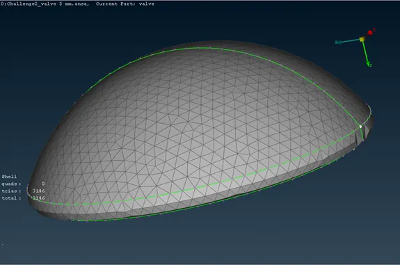
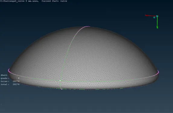
- Mesh length should not be given larger than the surface inorder to get the fine mesh. The compariosn is shown in the below images to validate the point
RESULT
The given Geometry was meshed according to given parameters for different target lengths.