Week 3 Challenge : CFD meshing on Turbocharger
OBJECTIVE
For the given model, check for the geometrical errors ,create and assign PID'S, Perform surface mesh and volumetric
mesh
Target length for different components are:
• Blade stage 1= 1mm
• Blade stage 2= Imm
• Impeller= 2mm
• Shaft rotor= Imm
• Turbo casing= 5mm
Compressor casing- 5mm
• Inlet casing cover= 5mm
PROCEDURE
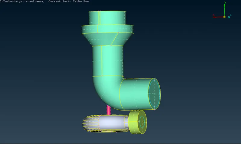
Step 1:Topology Cleanups
Go to geometry checks and select single cons, cracks, overlapped surfaces etc.
• Delete all overlapped Surfaces using delete option.
• Delete unwanted instersected surfaces
• Use of con projection tool, create cons on faces and delete extra surfaces.
• Fill and create faces for solving single cons.
• Delete unwanted triple cons.
• Close the inlet and out of compressor casing and turbocasing
Step 2: Create and assign PID'S
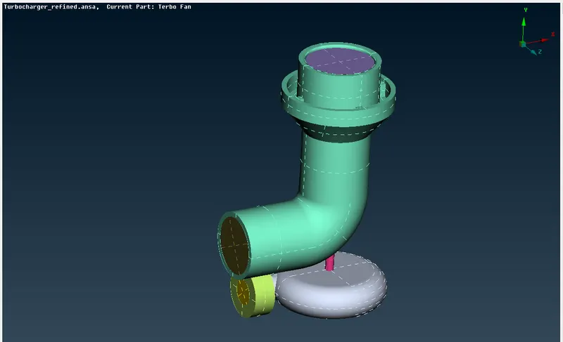
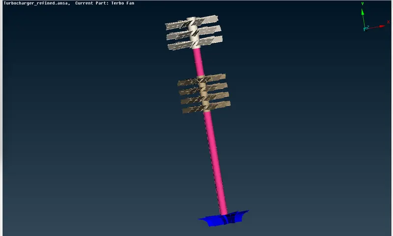
• Go to properties option.
• Create new PID'S and assign to different components as per the video.
• Delete empty PID's
Step 3: Surface Mesh
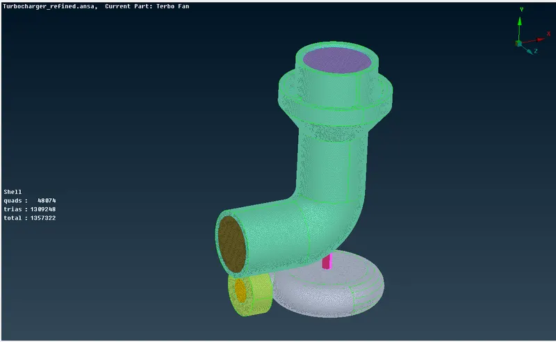
- Change the target length, minimum length and maximum length as per the given data.
- Do surface mesh on each part.
- Check for any unmeshed surfaces.
- If any unmeshed surfaces are present, mesh that surface seperately without giving perimeter and macros.
- Perform macros cut option to smooth the mesh.
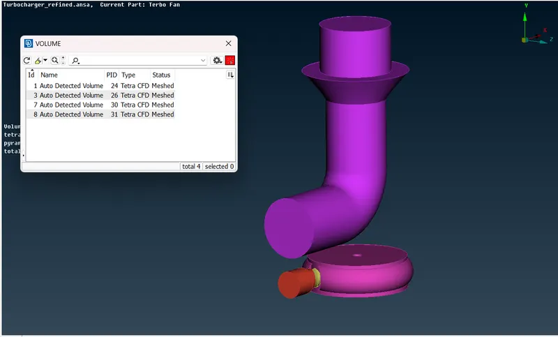
Step 4: volumetric mesh
- Click on define option in volumetric mesh. select whole db and click ok.
- From the autodetected volumes select only the required volumes and delete others.
- Right click on each list and do remesh.select tetra CFD.
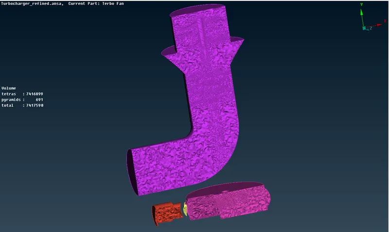
- Do volumetric mesh on all volumes and save the model
LEARNING OUTCOMES
• Understand how to use intersect tool.
• Understand how to perform geometry checks, creation and assign of PID'S and perform surface mesh.
• Understand how to perform volumetric mesh.
RESULT
In the given model, checked for the geometrical errors ,created and assigned PID'S, Performed surface mesh and volumetric mesh.
Geometry model link
https://drive.google.com/file/d/1SYbXFDcDUZLBCyg4U_VwovdBgdd5UzCz/view?usp=sharing
COCLUSIONS
Location where we had blades at that locations elements are coming smaller in size and away from blades size of elements keeps on increasing.It is because of different target length in surface mesh.