Week 3 Challenge : CFD meshing on Turbocharger
Aim:- Avoid Geometricals errors and do topo cleanup on Turbocharger Model. Create different PID'S and assigned to the model.
and perform surface mesh and volumetric mesh on turbocharger model.
Target lengths for surface Mesh:-
Blade stage-1 = 1 mm
Blade stage-2 = 1 mm
Impeller = 2 mm
Shaft rotor = 1 mm
Turbo casing = 5 mm
Compressor casing = 5 mm
Inlet casing cover = 5 mm
Procedure:-
1. TOPO geometrical cleanup:-
Here in the model found out the glitching of the surface. Giching is form when there is overlapping of surfaces. To check the errors go to TOPO option in faces. Drag the cross box around the model then tripple cons and single cons will be visible.
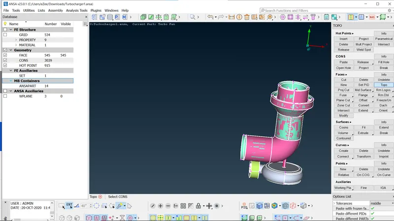
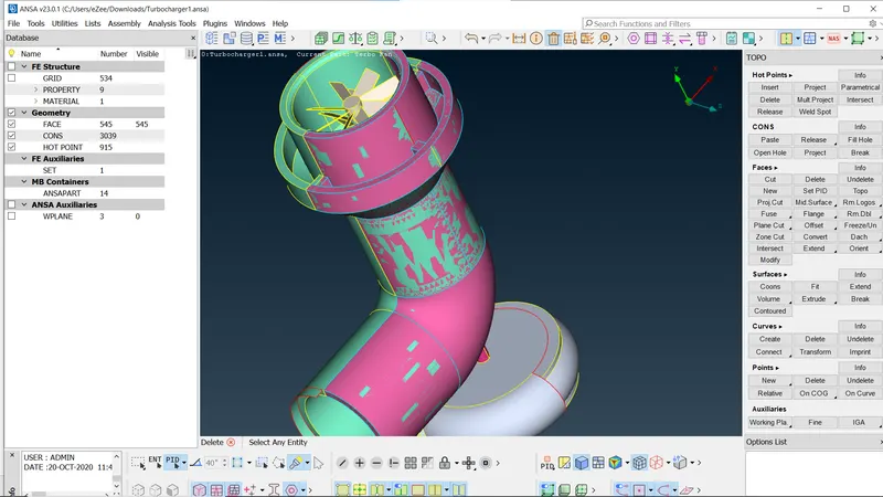
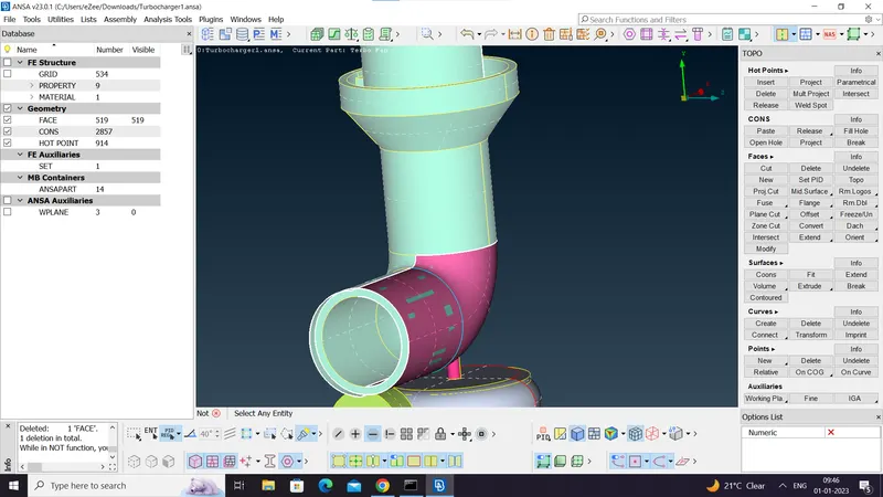
Here pink gleeching on the green surface is observed. Se we need to remove the pink surface. To remove the pink surface find out the pink cross edge of the surface.
use deleate command and find out the pink surface cross edge in order to deleate the surface. (The conclusion here is colour of PID nad cross edge of PID are same in colour.)
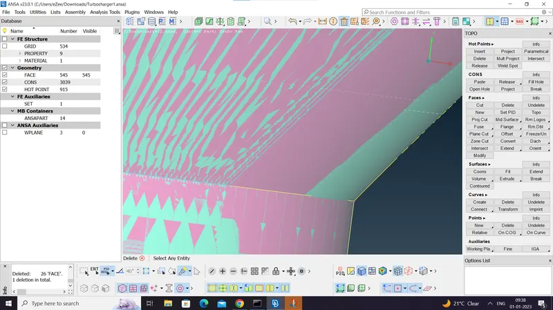
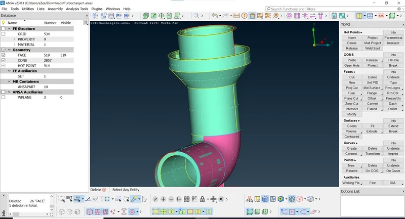
Here on bottom surface also there is gliching of pink surface. We hide the green surface using OR option. so the inner surface is visible.
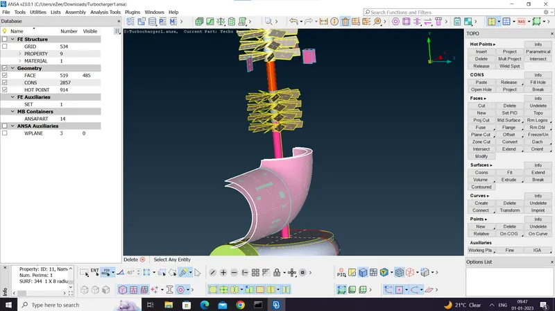
After removing the green surface. the two unwanted pink surface are present here. deleate these two suraces. and click on the ALL option.
so the all the hided surface will come back.
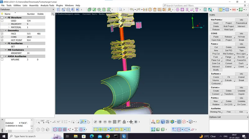
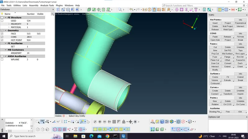
we delete this extra surface using delete + ENT method. click on delete then click on ENT and click on the surface. it will delete the surface.
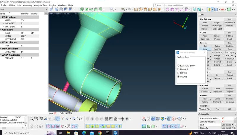
After deleting the surface we will patch the surface. go to NEW and hold it for a moment. select COONS option. cllick on the loop option. using loop select all the
cons at the same time. mddle click and it will patch the surafce.
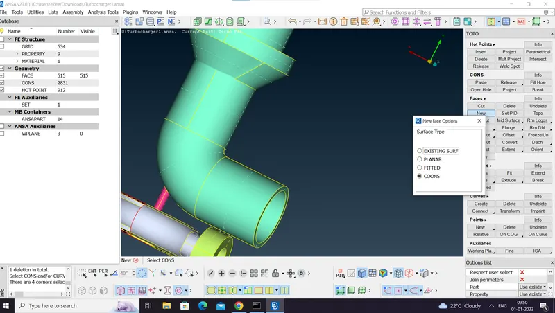
In top side. the red lines which is nothing but single cons. we have to patch the surafce. But the boxes are interfering in surface creation. Near boxes tripple cons are formed.
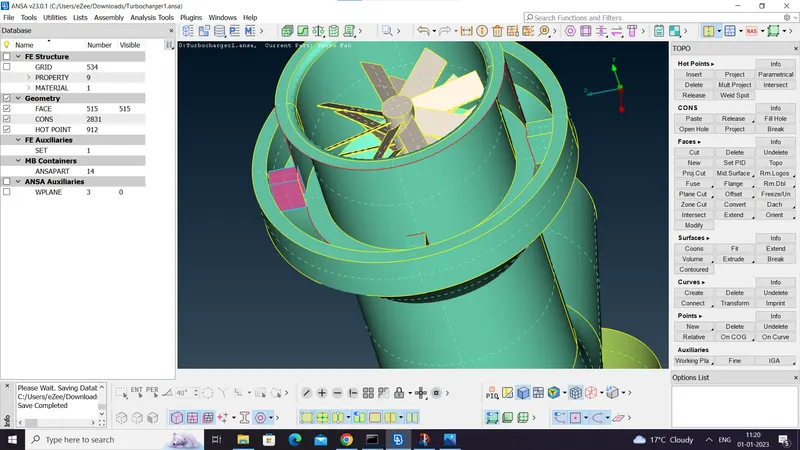
To delete the boxes we hide the green PID using OR option. delete the box using delete option. by click on delete and then click on surface then middle click.
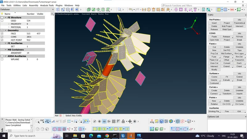
delete the box using delete option. by click on delete and then click on surface then middle click.
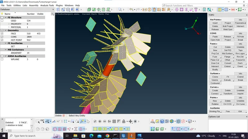
Now click on the all hided surface will come back. now trying to patch the surafce with coons option with loop command.
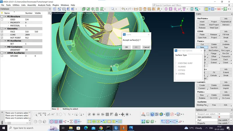
The preview of surface using loop command is not good. so projects the box point on the next surface edge using multiple projection.
click of multiple projection. select all the nodes one by one. middle click. select the edge.
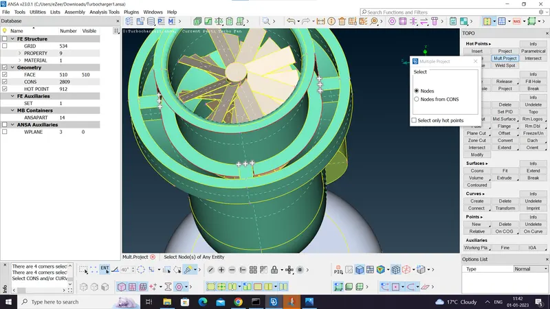
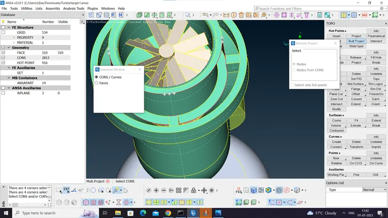
now using coons with the projected points create the surface near the boxes.
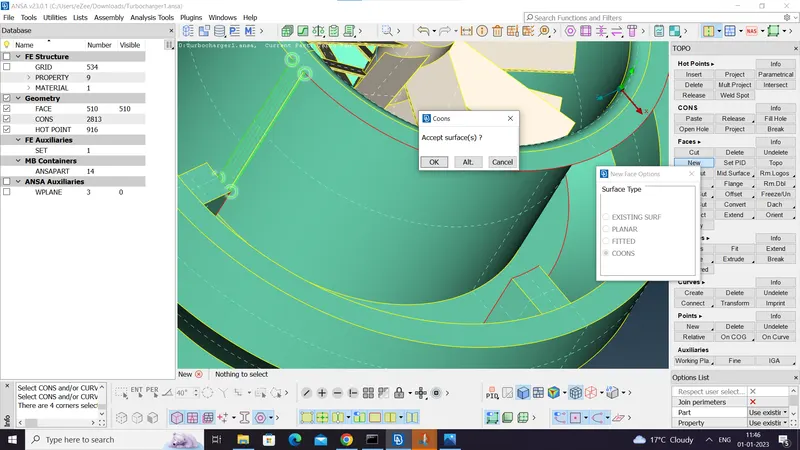
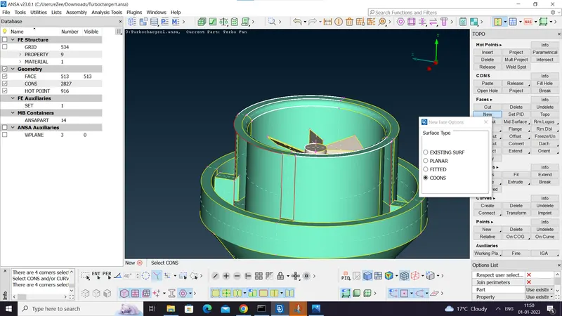
Finally patch the surface between the boxes using Fill hole. G o to fill hole. selct all the cons using loop. Middle click surface will be patched.
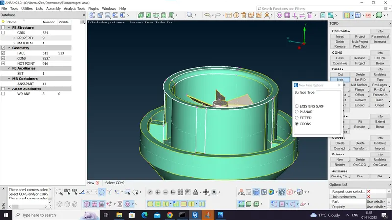
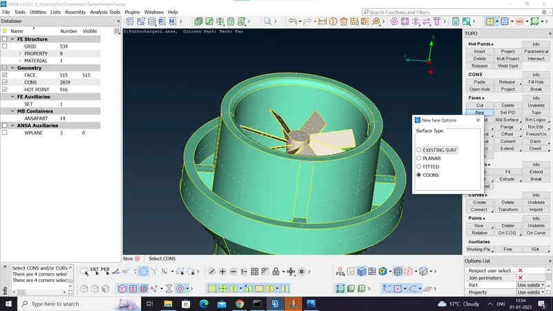
Check for error using wireframe model by Ctrl+shift . here there are single cons means either the surface is missing or left.
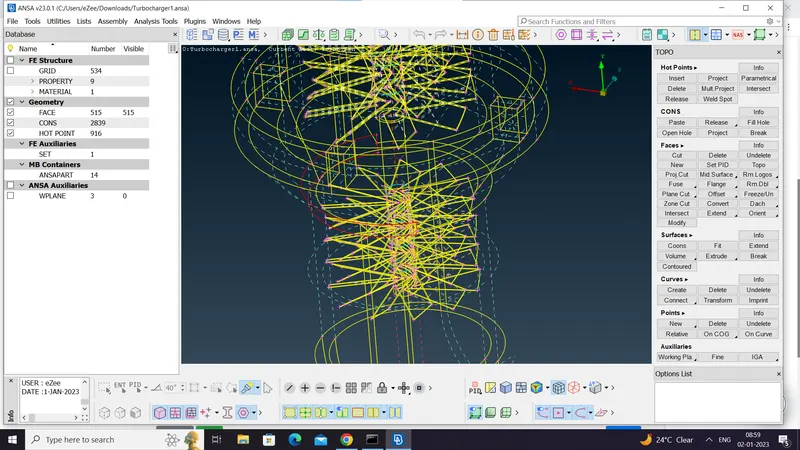
we hide the top and bottom surface using or (-) option to create the surface there.
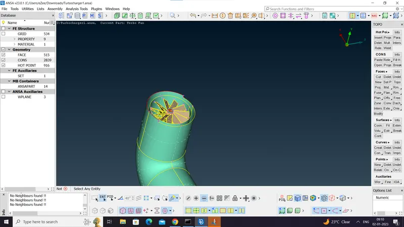
Here is is observed that the vertical surface is intersecting with the another surface. Join these two surfaces using intersect command.
click on intersect. it will ask to select the first surface. select the curved surafce first. then middle click.
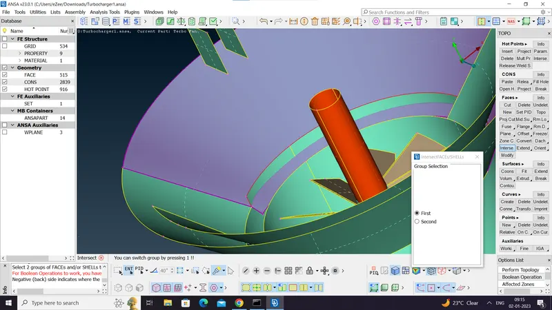
Now select the second surface and middle click. Two surface will be joined.
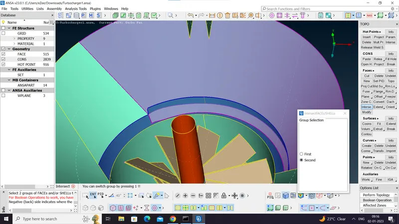
After interesecting the two surafces tripple cons are observed here. for better understanding go to wireframe mode.
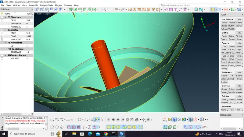
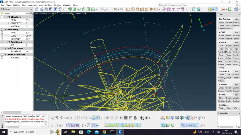
We delete the two surafces because tripple cons formed between these two surfaces and there are three surafce overlap.
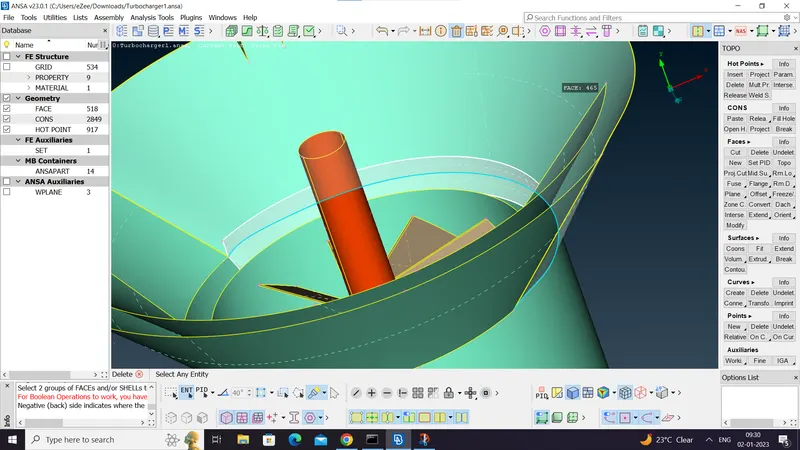
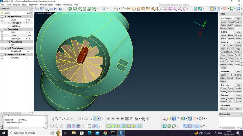
Near blade triple cons are formed. the blades are brown in colour but in middle of blade there is orange colour gliching. delete the orange surafce using delete option.
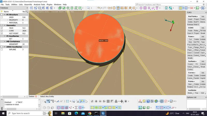
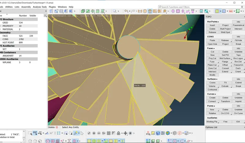
After deleting the orange surface still tripple cons are there. need to check is there another surface present below.
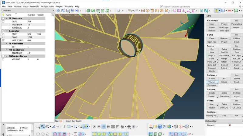
There is no another surface here stiil it shows tripple cons. in this case go to Cons. select the release option. then select the cons. it will convert it into three single cons.
Release option convert the tripple cons into three single cons and double cons into two single cons.
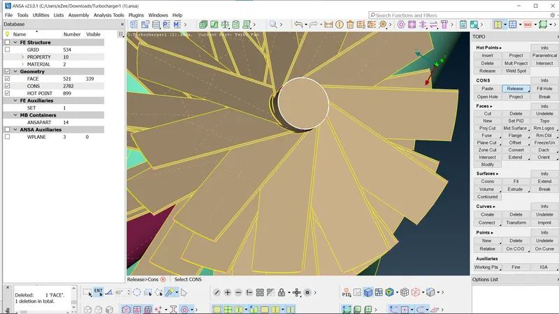
release option convert it into single cons. now we delete the additional hot points using hot points delete option. click on delete then select the hot points.
some hot points may not be deleted beacuse they are shared with other surafce.
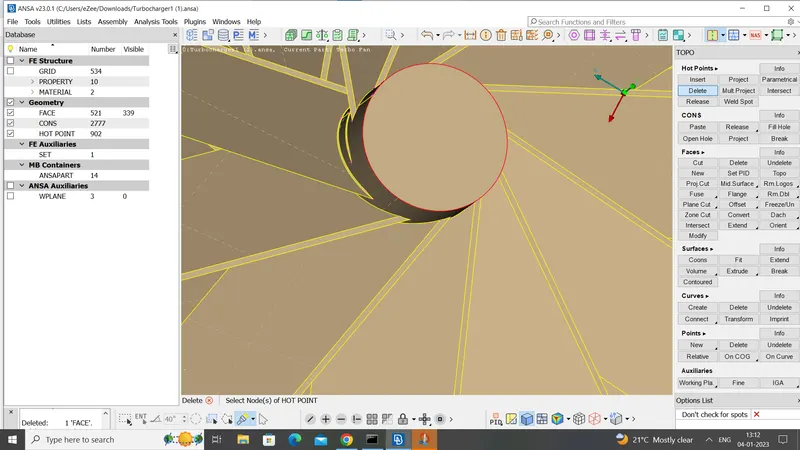
now use topo command because topo exactly apposite to the release command it will convert two single cons into double cons.
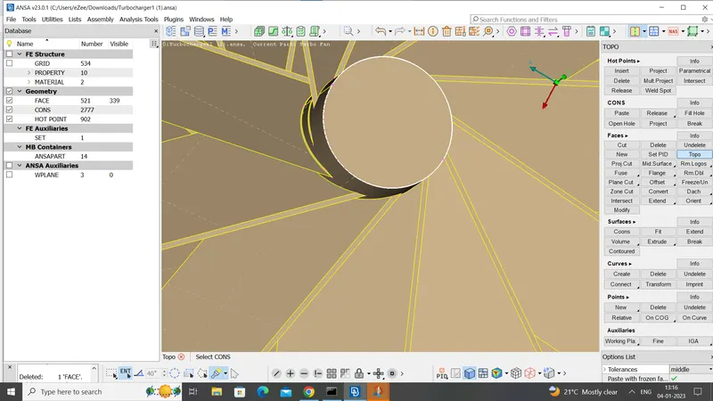
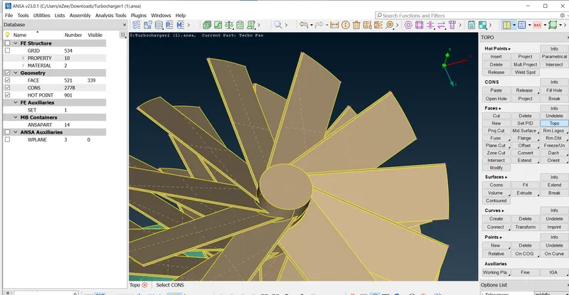
In bottom side also single cons are formed beacause surface is missing here. try to patch this surafce using Coons and loop option. Click on new surafce. select coons. selects cons using loop.
middle click. then it will patch the surafce.
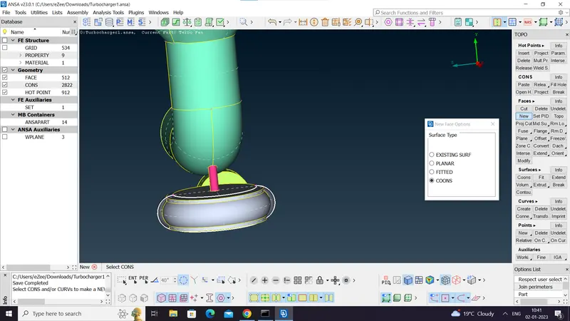
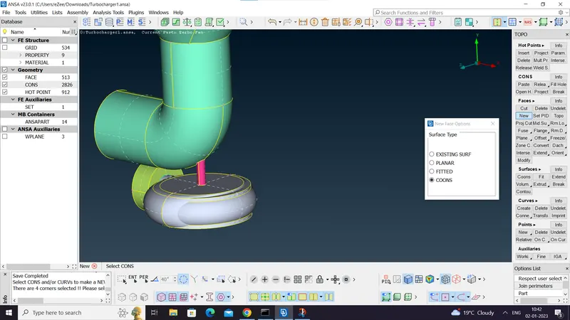
The surafce craeted using coons is not accurate try using Fitted option.
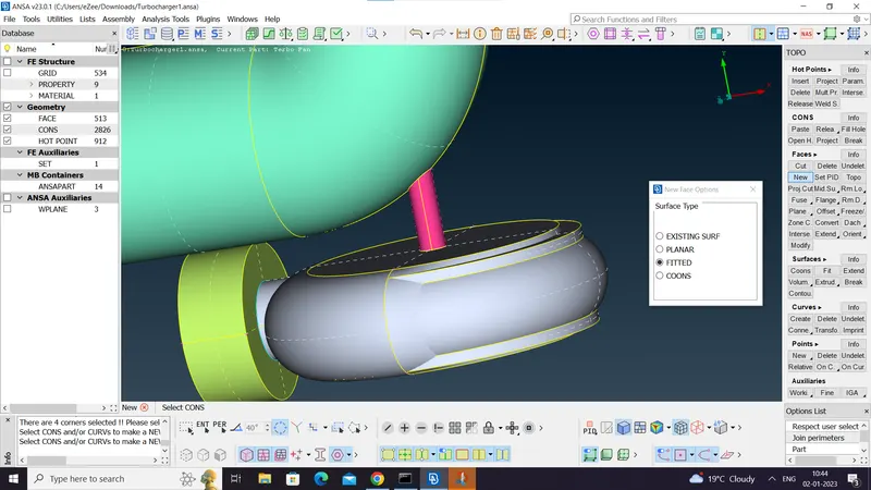
Suface created using Fitted option is also not accurate. we create multiple surafce using multiple hot points. For that use parametrical option. click on parametrical. then give length as 0.5 mm beacause it consider the selected line as 1mm and create hot points at middle.
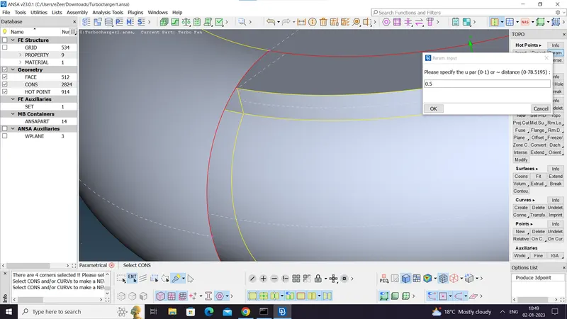
Create multiple hot points on both the apposite sides of line using parametrical option.
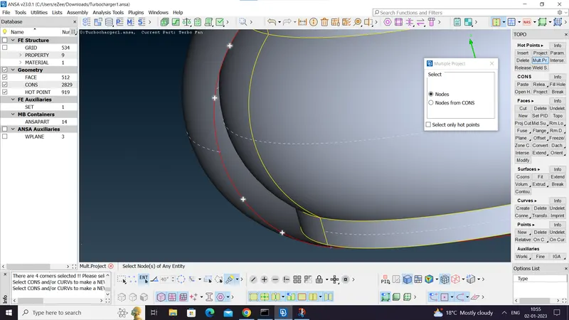
Now patch the surafce one by one using COONS nad ENT method. create the no of surface in order to create the smooth geometry of the surafce.
select coons option. select ENT option. select the cons and . Middle click it will patch the surafce. simillarly patch all the surface using created hot points.
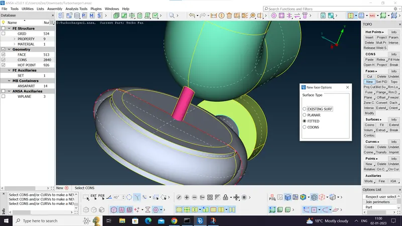
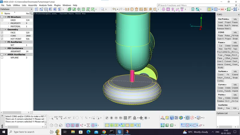
Now check the any unpatched surface is present or not. for that turn off doble and tripple cons. and turn off the shadow mode and wireframe mode.
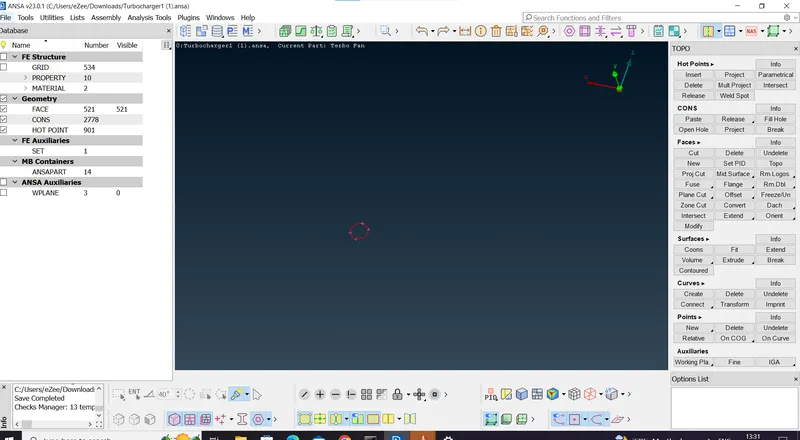
We can also find out this using geometry checks. Go to script. then select the checks option. in checks select geometry option. enable single cons option. and exacute it.
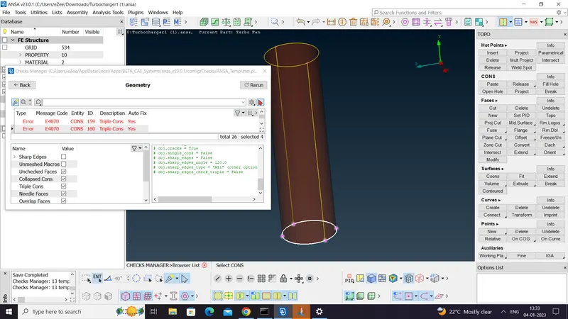
No we go to PID manager and hide the necessary PID's in order to fix the single cons.
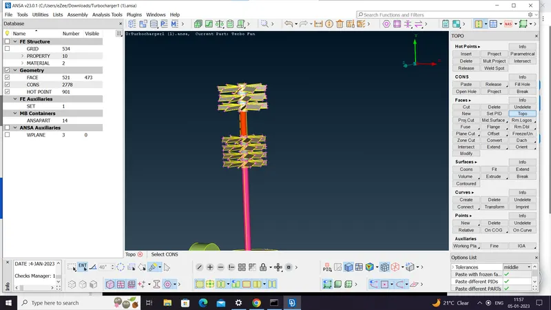
Here we try to fix that single cons using topo here. go to topo and select the single cons portion.
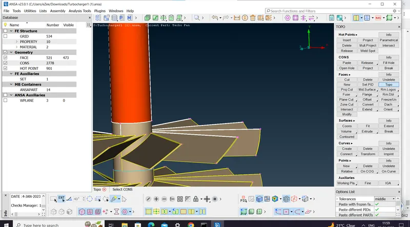
After using topo the single cons converted into tripple cons. now we are solving for tripple cons errors. first go checks. click on geometry.
execute it and find out the tripple cons errors and fix it.
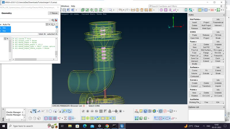
solve the bottom tripple cons errrors.
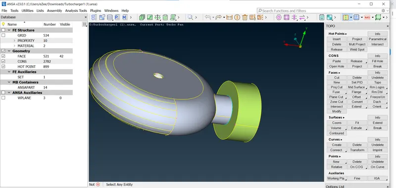
we isolate the tripple cons surafce. then using neighbours options we enabling neighbours. Sometimes 3 tripple cons is not an error it just an warning.
here the tripple cons are formed but there are shared eith two different entities so neglect this error.
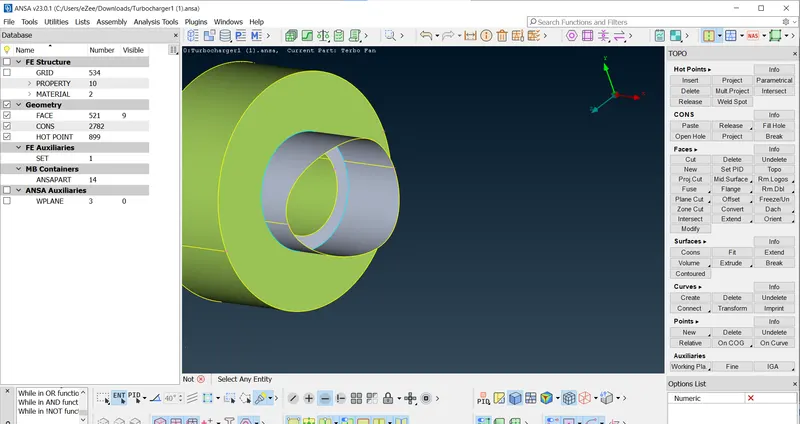
Now again hide the unnecessary PID'S and try to fix the blade shaft tripple cons errors. Here tripple cons are present on the shaft blade.
we hide the neighbouring surafce usinf or ENT option. and try to delete the additional middle surafce.
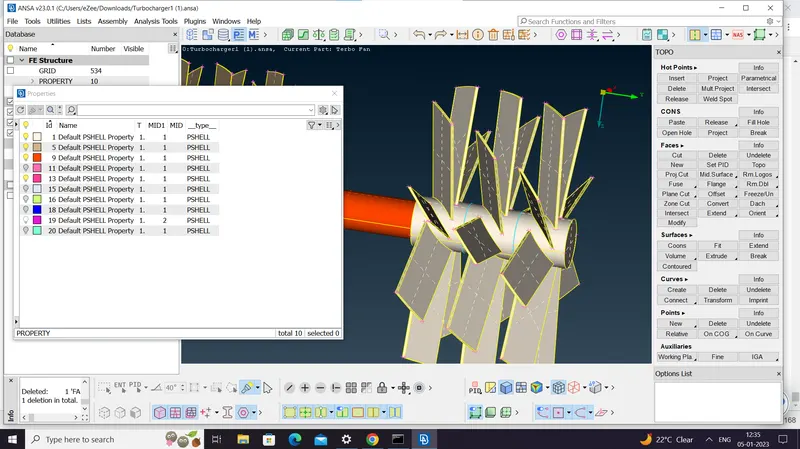
Now hide the adjacent surafce of shaft and delete the middle surface and continue this process and solve the tripple cons.
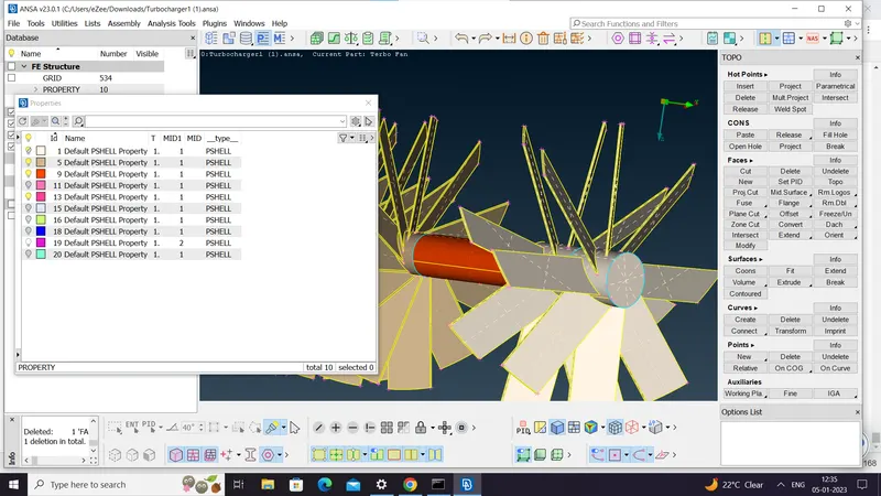
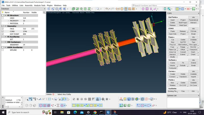
Here in the shaft near pink PID even if delete the extra middle surafces. there is gliching of pink and brown colour PID and tripple cons are formed there. the blades are brown in colour so the middle PID of blade
should also brown. when trying to delete the pink surface of gliching area whole PID of pink colour getting deleted. now we use projec method. go to cons then project. select the cons. then middle click. then select the surafce.
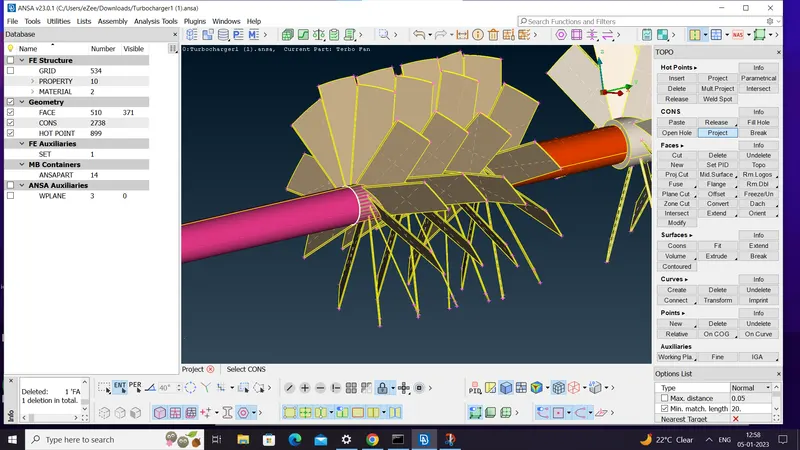
it will create the cut on the shaft. isolate the shaft and delete the cut part which is overlapping using delete plus PID region option.
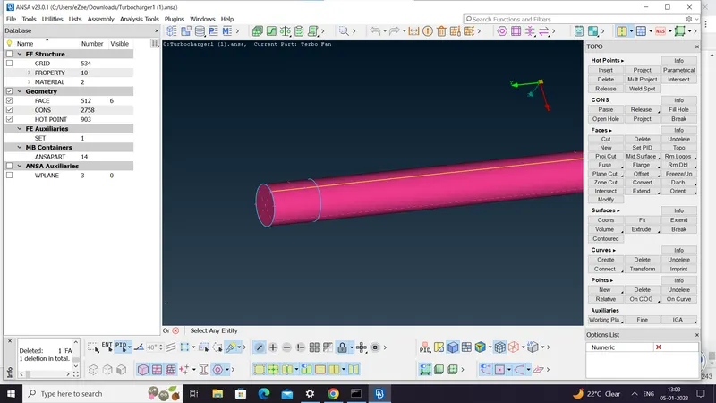
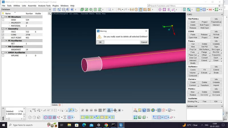
after deleting cut part click on all option.Now there is no gliching of surafce but still tripple cons are present there. we delete the middle addition surafce there.
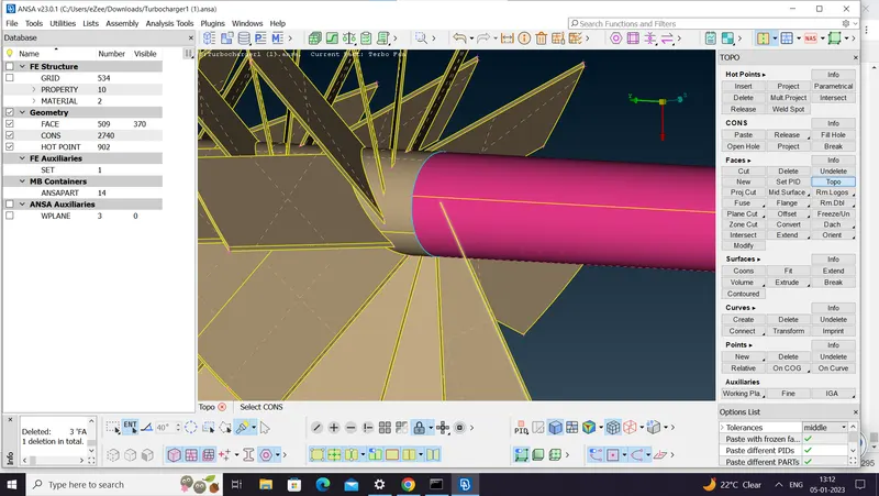
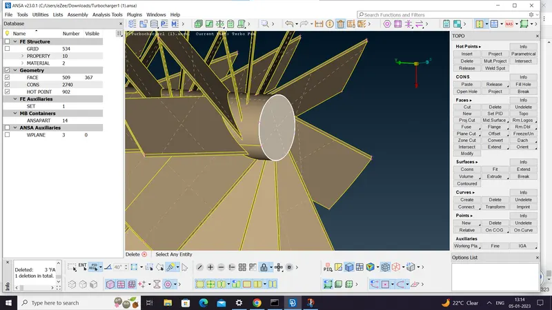
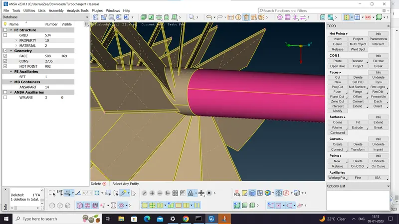
In bottom blade surface also tripple cons are present. we delete the addition middle surafce because tripple cons are formed there.
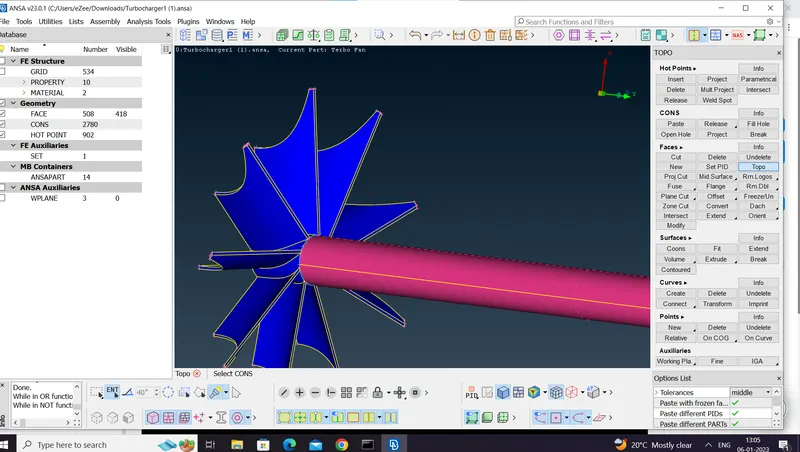
when we hide the shaft and try to delete the blade middle portion. the whole blade is getting deleted because of cross of middle surface also shared with the blade.
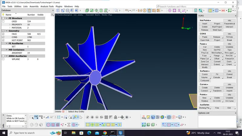
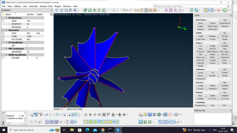
Now select the cut option. select the hot points and create the cut using two hot-points. now the circular surface is seperated from cons.
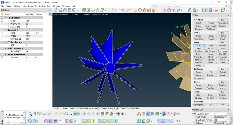
delete the middle surafce and pink rod surafce. thsi will make whole shaft as on entity.
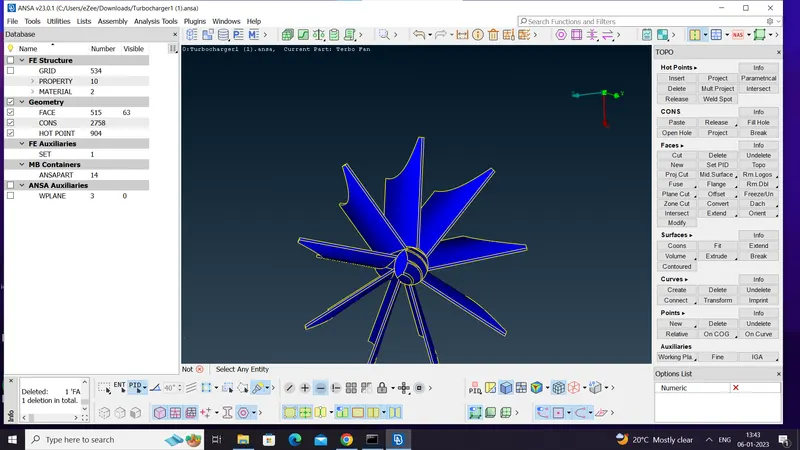
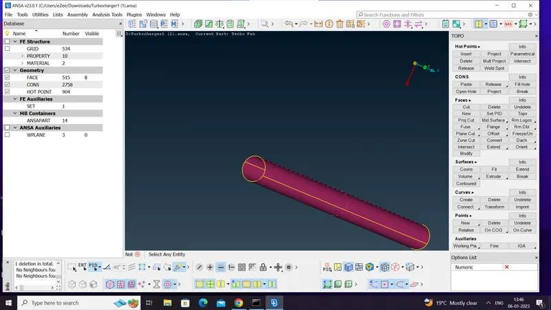
Now we again go to checks then geometry. there are no error than tripple cons which needs to neglect which is nothing but warning.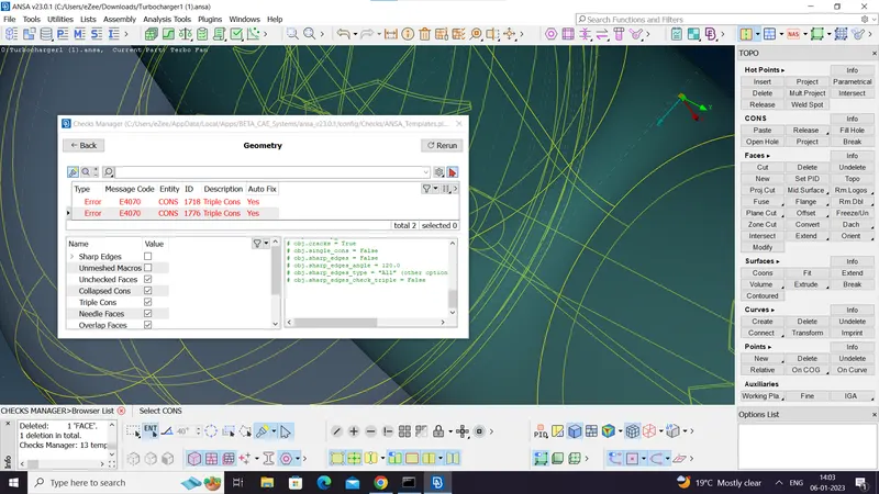
In order to perform the volumetric mesh the geometry should be closed. so patch the all the open surface in order to create close geometry.
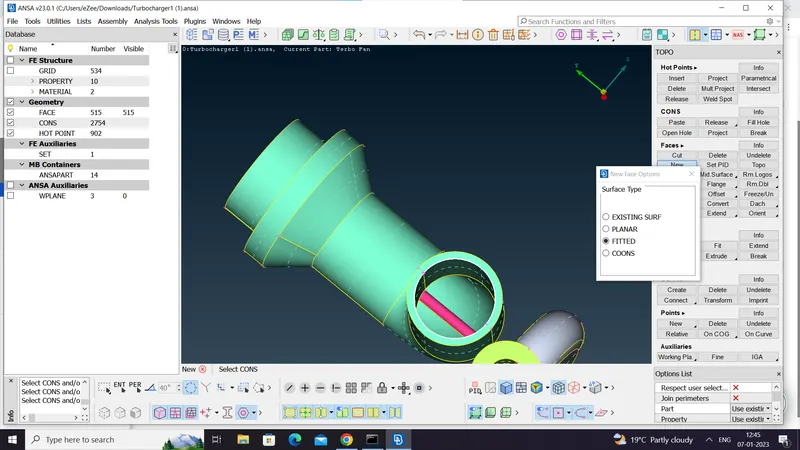
here the patch the surface using fitted option with loop commnad.
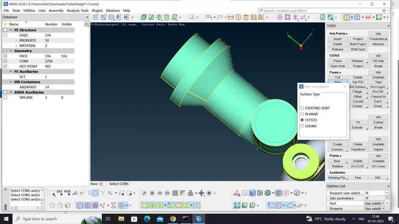
simillarly patch all the surafces.
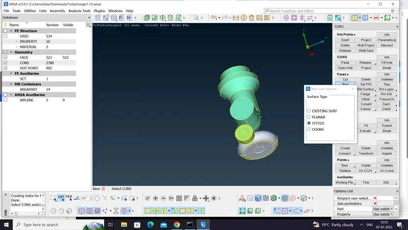
Now rename the PID'S before doing that we make one common PID for all the blade shaft. we assign the pink colour PID to the orange colour PID.
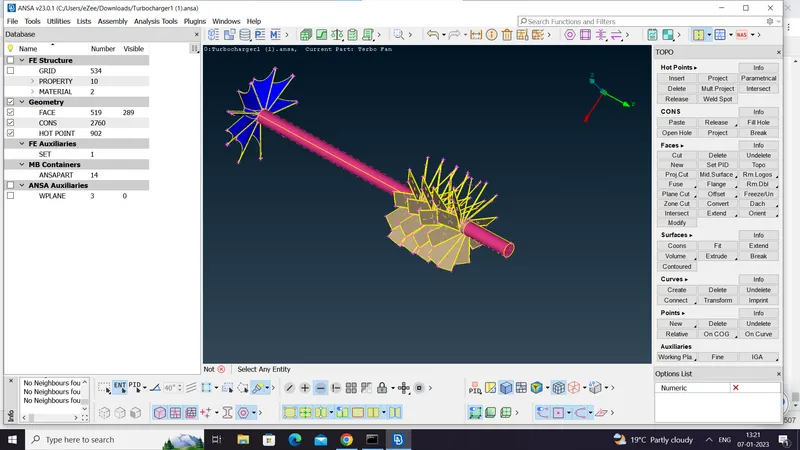
PID is now common for all the shaft. now delete the previous unnecessary PID. select the PID and delete it. it will shows us an error because we already replace the previous PID by another PID.
so no surface is left for PID. Now use compress method. select two PID'S and go to and click on compress option.
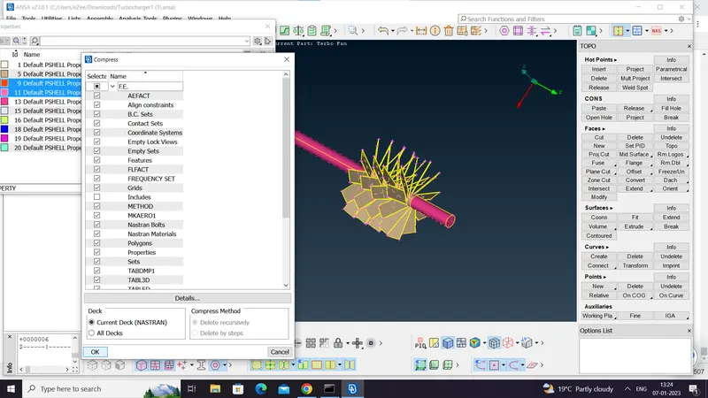
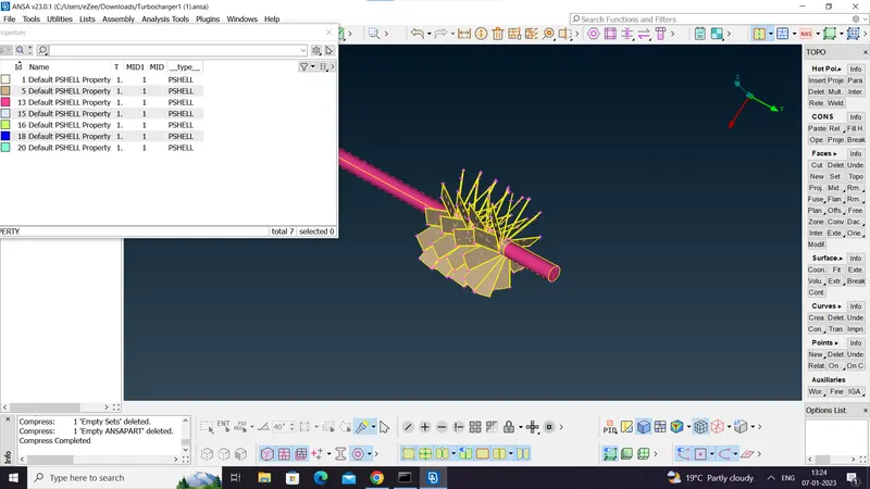
Now Rename the PID'S fo rdiffrent components also create new PID'S for casing inlet and casing outlet and assign these to the components.
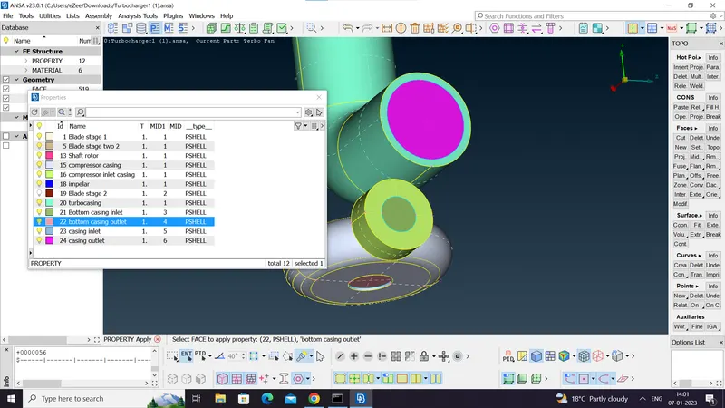
Meshing:- Now start the meshing. before going to surface meshing first do the volumetric mesh. In surface meshing use 2D elements called tria elements for meshing.
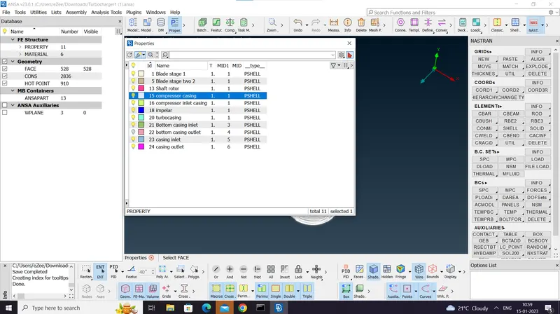
in volumetric mesh use 3D element for meshing. Start meshing using PID wise meshing. Start meshing with the compressor casing. Go to PID manger. click on compressor
casing PID and select show only.
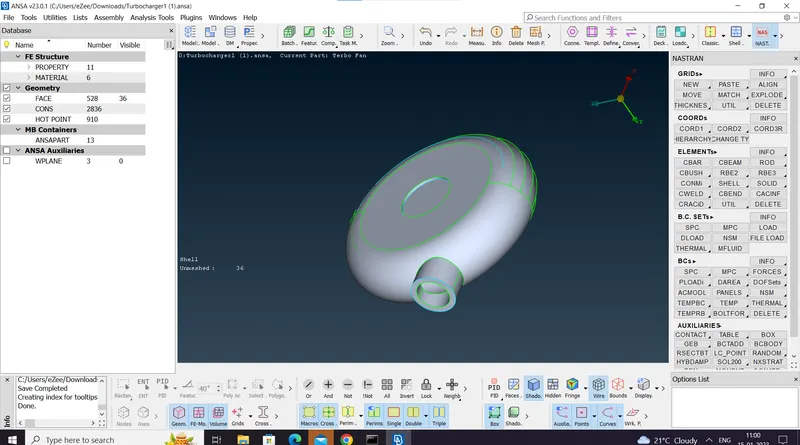
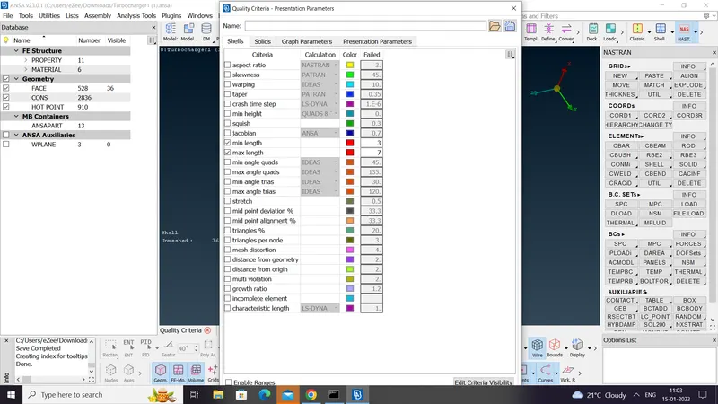
Go to quality criteria. give mesh length as 5mm for that give min length as 3mm and Max as 7 mm.
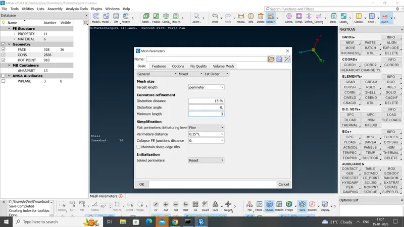
Go to mesh parameter and give target length as 5mm. min length= 3mm.
Go to perimeters and click on length give perimeter length as 5 mm. then select the object by cross selection. simillarly give macros length as 5mm select the object
by cross selection. Then middle click to confirm the selection.
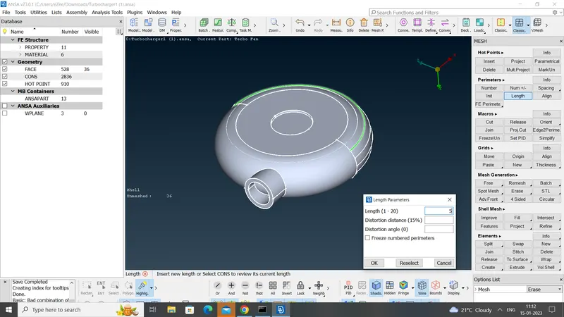
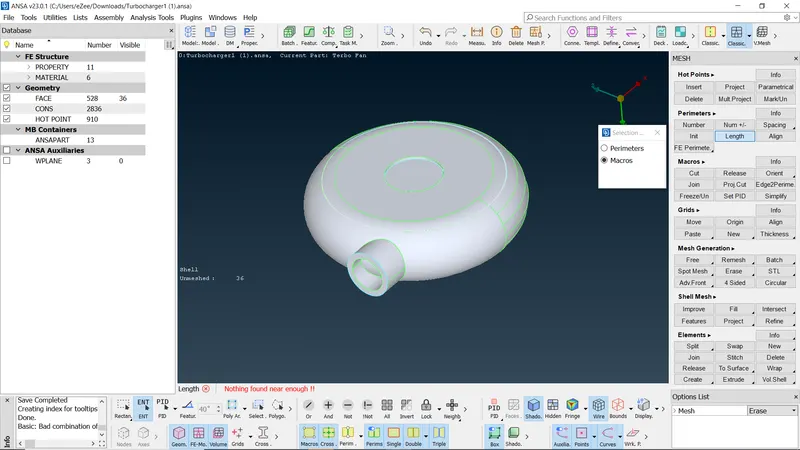
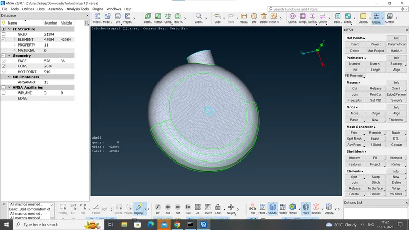
Simillarly mesh the mesh the remaining PID'S one by one. go to quality parameter give min and max target length. Also the give the element type as tria.
Go to mesh parameter give min and max target length. Then go to perimeter. click on length. give perimeter and marcos length to the object. then finally
go to spot mesh. select the PID it will mesh the object.
For turbocasing and inlet caing casing cover Target length= 5mm, Min =3 & Max= 7 mm.
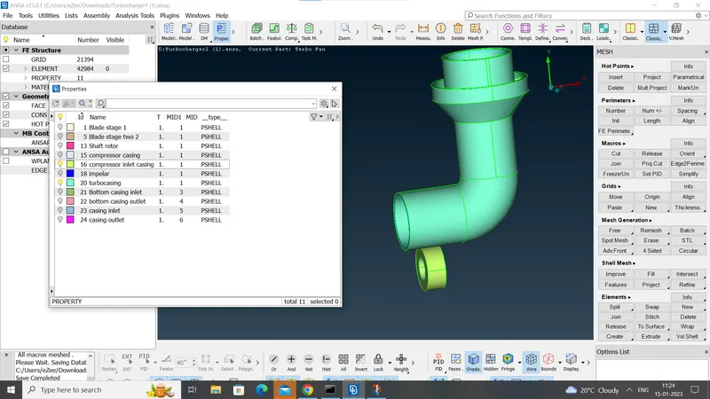
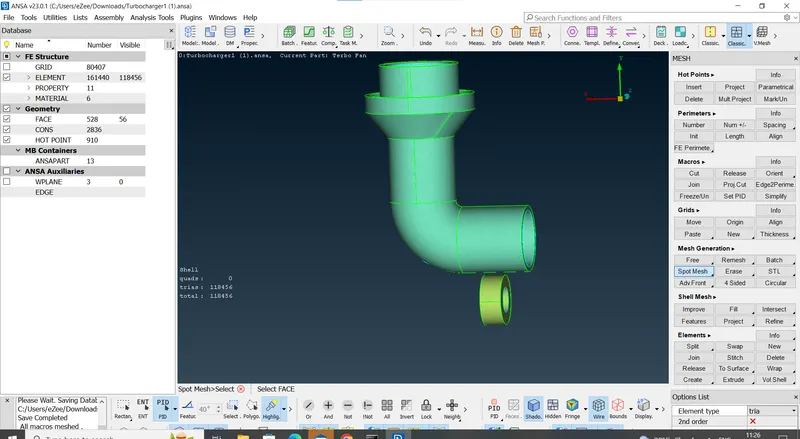
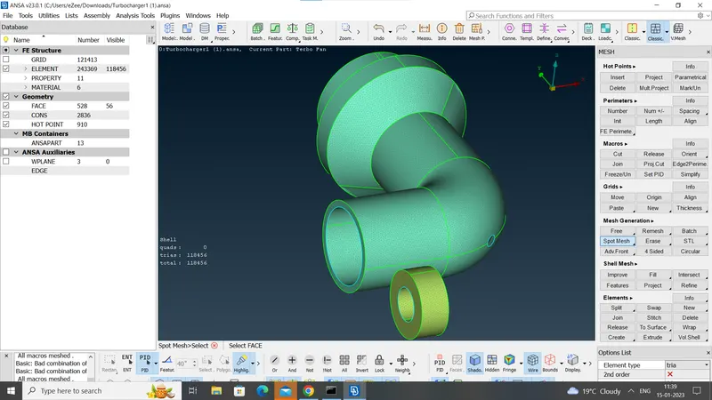
For impellar Target length= 2mm, Min =1 & Max= 3mm.
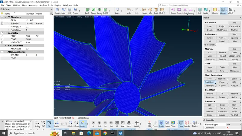
For shaft blade stage 1 and 2. Target length= 1mm, Min =0.5mm & Max= 2mm.
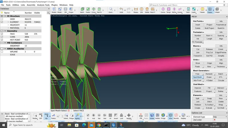
Now do meshing for bottom casing inlet and casing inlet and for casing outlet.
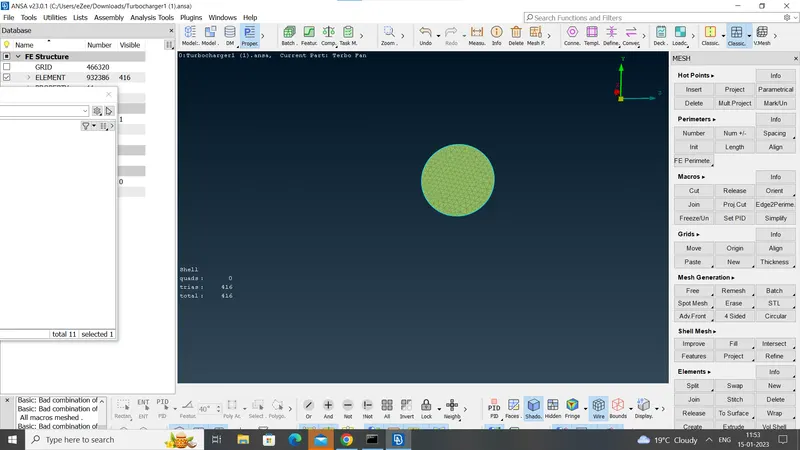
Now fix the meshing of turbocasing where there are two surface present one over another. first mesh the first surafce then isolate the first surafce.
then mesh the second surafce. We can right click on the unmeshed surface and click on show only it can also show the unmeshed parts of the surface.
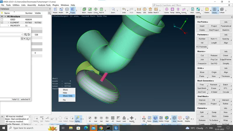
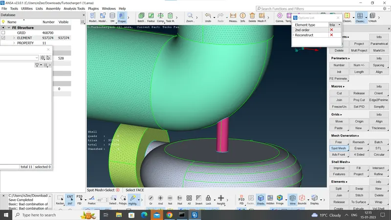
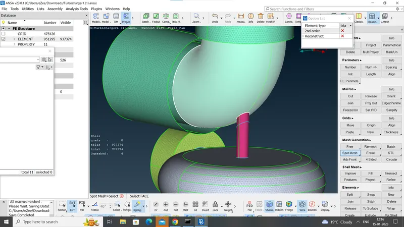
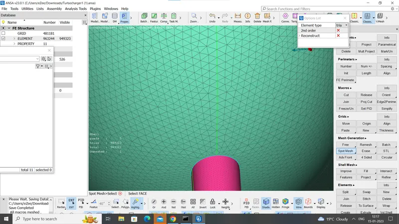
Here near the shaft rotor surface of turbo casing and compressor casing surface the transition of mesh is observed. The reason behind this is after meshing twodiffrent surface having diffrent mesh length. at the contact surface transition occue there means mesh length varry there. for that use macros cut option.go to macros. click on cut option. draw the cut of any shape around the transition in order to isoate it.
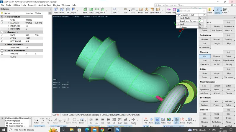
Volumetric Mesh:- In surface mesh we mesh the object using tri element which is nothing but 2D elements. and in volumteric mesh mesh the object using 3D element which is nothing
tetra element. For starting volumteric mesh go to define. click on it. select the whole db.
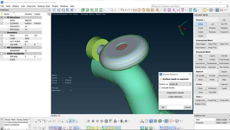
click on ok then it will show all error presents. Now then go to list. there are number of unmeshed surfaces. check the each surafce one by one. by right click on the surface
and click on show only.
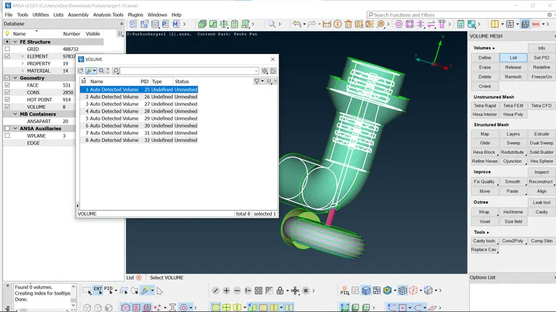
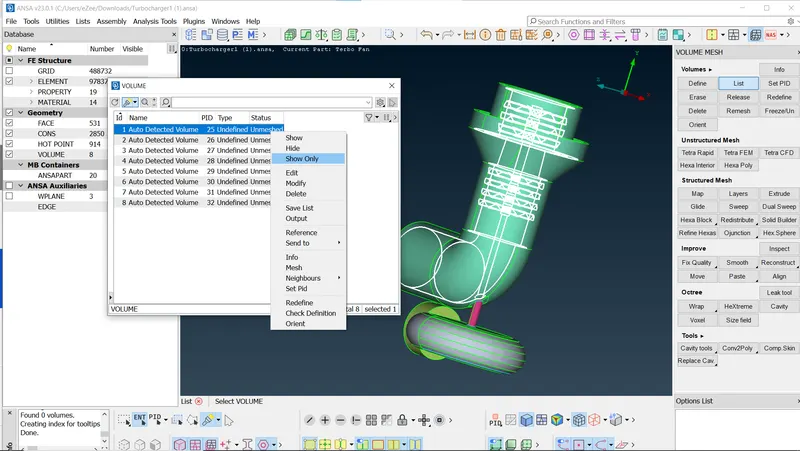
In volumetric mesh we need volume components for meshing. Not any need of thickness components and innerside components.
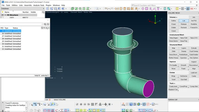
The above component is volume component of turbocasing which need to keep for volumetric mesh.
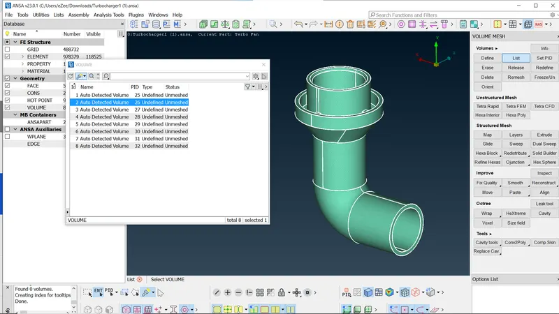
This is thickness component of turbocasing not need of thickness component because fluid not flow directly to thickness component so such component can be deleted.
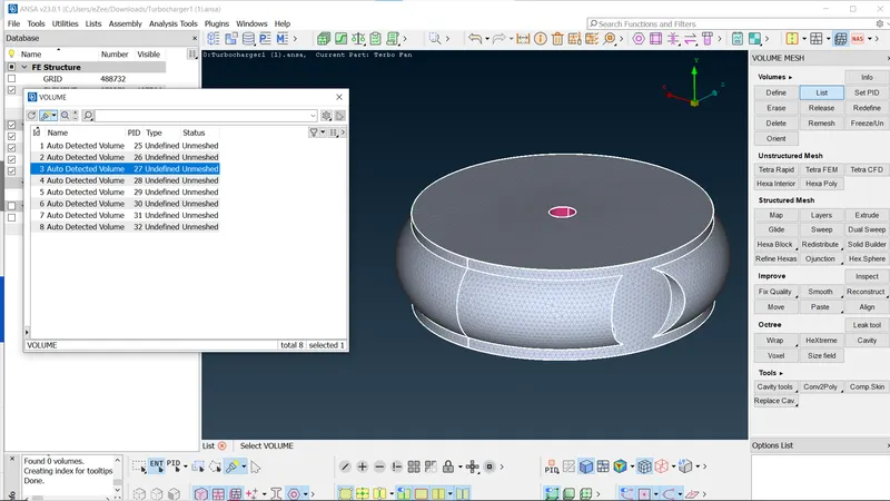
Compressor casing volume component need for meshing so need to keep it.
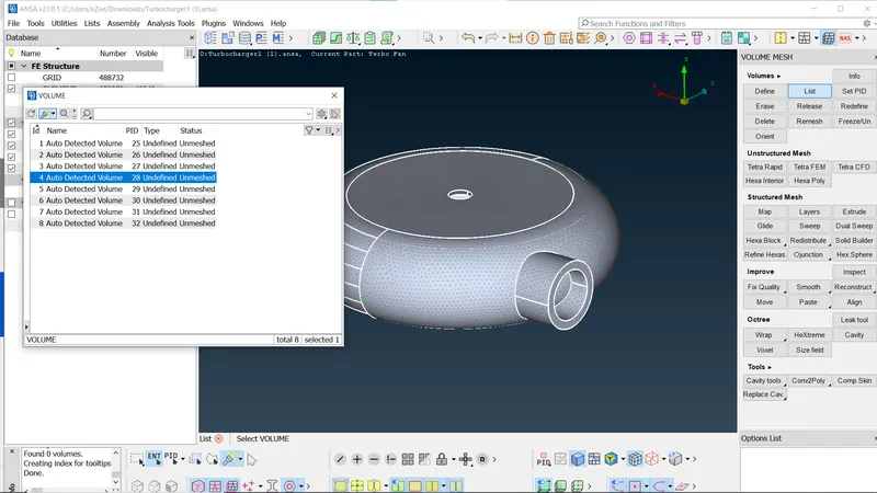
Thickness component of compressor casing need to delete.
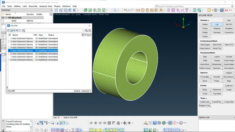
Thickness component need to deleted.
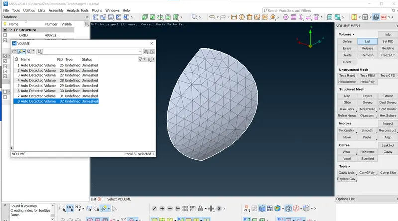
this surface need to keep for volumetric mesh.
on the list of surface which is showing as unmeshed. right click on the surafce.click on mesh it will mesh the surface. Or use Remesh option.
click on remesh option. then click on the surafces. and mesh the each surafce one by one.
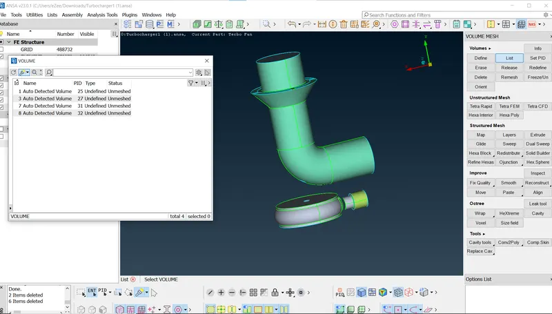
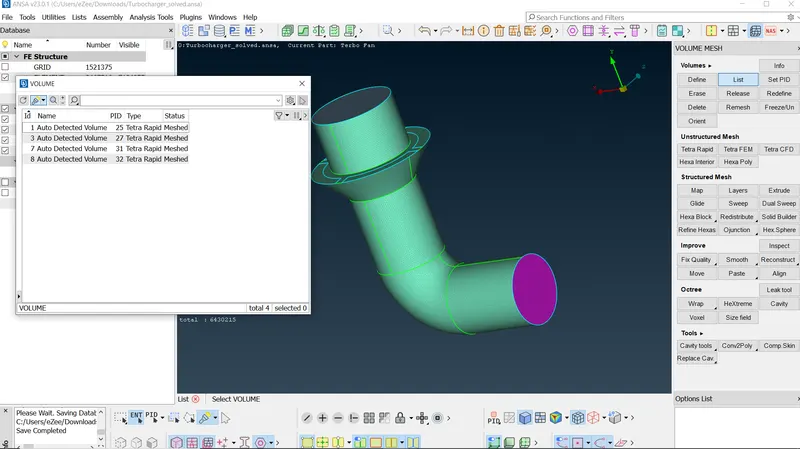
Final volume meshed component :-
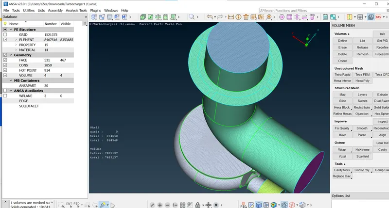
If we go to the topo. we saw the overlapped volumes on the objects. this is because the volume we created are now part of the volume of the object.
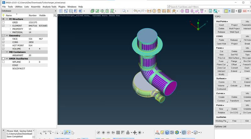
Here turn off the Geometry and FE mode so the gliching can be avoided.
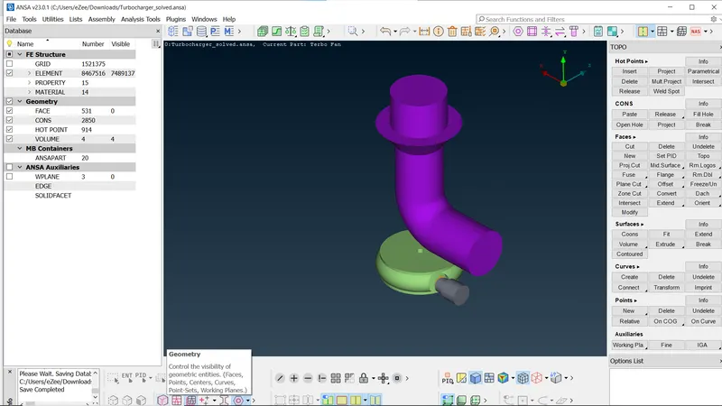
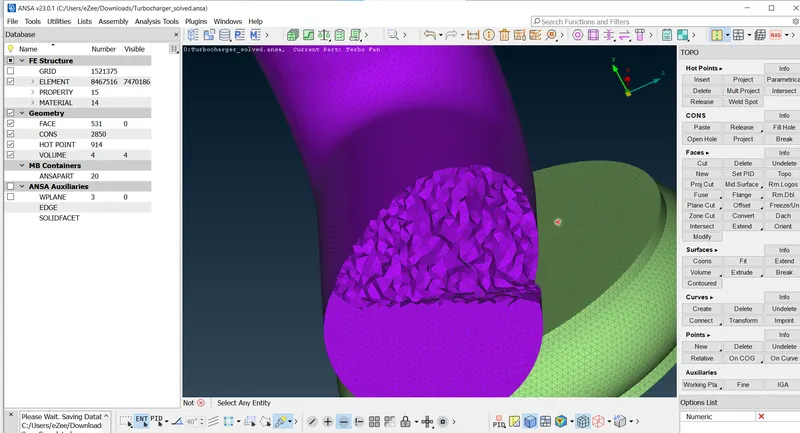
Using ENT and or option we can create small cut on the meshed surface here. It will show the elements presents inside the surafce.
All these are Tetra element of volume meshed surface.
Unable to submit the file so i have shared a file with my google drive folder:-
https://drive.google.com/file/d/1WK6D61SEWJM4Fxvx0B1SyNZdlAnZ8G_D/view?usp=sharing