Week 2 Challenge : Surface meshing on a Pressure valve
Aim:- For given Pressure valve work on geometrical errors and perform Topology cleanup. Perform meshing on the model and explain the meshing process for given target length.
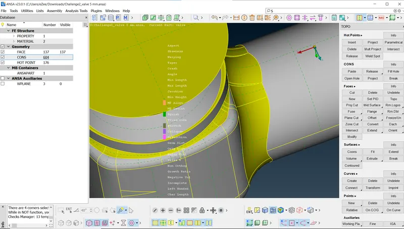
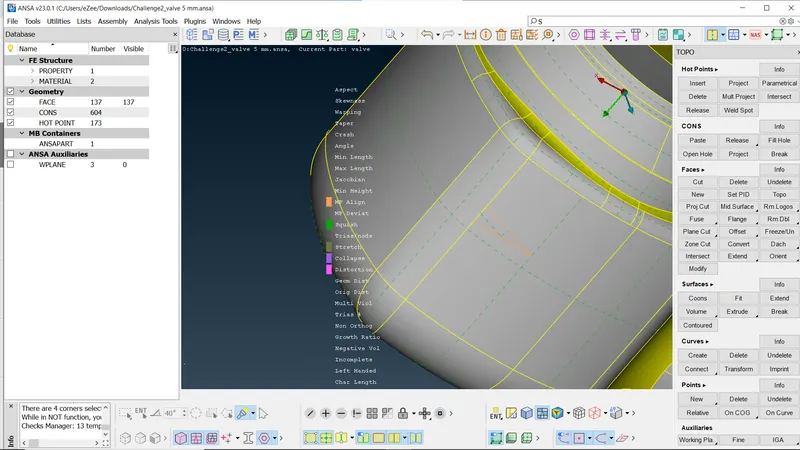
Topo and geometrical cleanup:- we want to perform the volumetric mesh for that first surafce mesh needs be done. For volumetric mesh the geometry should be closed in order to perform the meshing. In topo plane we patch the surface in order to create the close geometry using (Fitted,Coons,Fill hole) commands. After this process we check for CONS for single cons and tripple cons for the errors.
Single Cons:- Surface missing.
Tripple Cons:- Three surface presents.(Need to convert it into double CONS)
In the model we patch the surface by following process:-
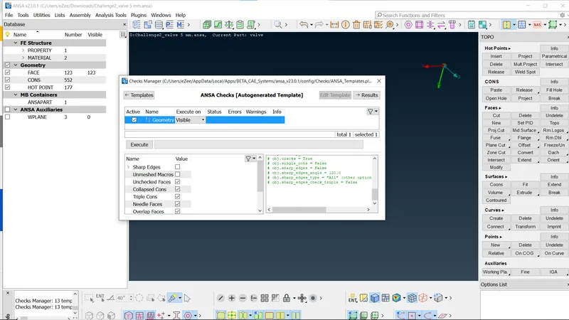
To check the errors go to scripts.Go to checks then click on geometry. in geometry go to templetes out of option select ANSA checks. Enable option and click on execute. then it will show errors. 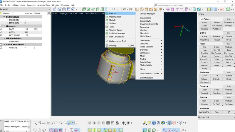
- Go to surface. Click on New and hold it for a time. Then select existed surface. select all the cons of patch one by one. Or directly select all the cons using LOOP tool.
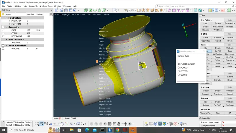
- After selcting the CONS select the surface by selecting the cross edge. then middle click. It patchs the surface.
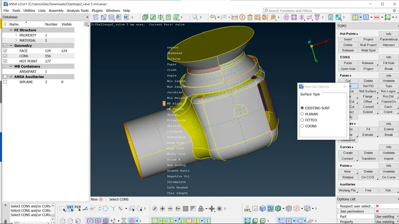
- Simillarly patch the surface using Fitted. select fitted. Select all the cons. middle click. it will patch the surface.
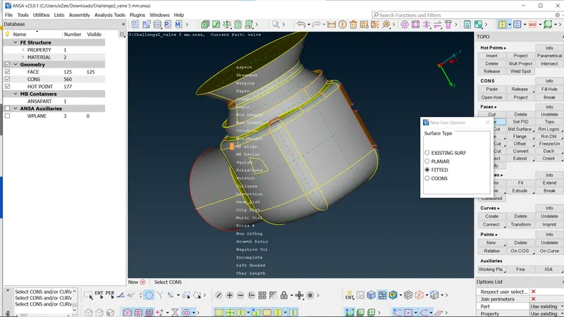
- Simillarly patch the outlet of valve using Fill hole. Go to cons. click on Fill hole after clicking select the hole then middle click. it will patch the hole.
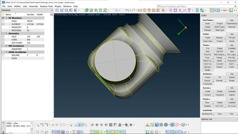
- We patch the bottom surface by Fitted. In order to do that go to wireframe mode (ctrl+shift) then selct the cons now this time selct cons one by one. First we select one side circular cons then complete the surface. simillarly we select other side circular cons using fitted create another surface. so here we create the surface in two shifts.
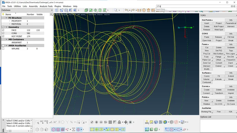
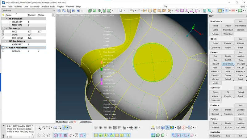
- Now we remove the patch surface lines using cut option. we also remove the lines which are close to each other for better mesh quality using cut method because we have given the mesh length as 5mm.
Meshing process:- Now we create PID. open PID manager. right click. click on NEW option. click on Pshell. give name for PID. by using this create multiple PID's for all components.
PID'S= inlet, outlet, body,bottom surface, valve head, spring, column.
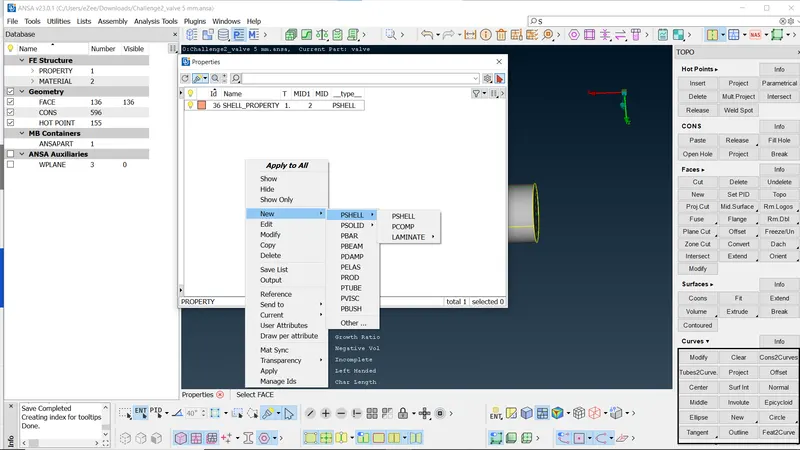
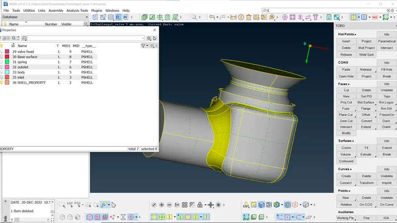
Now assign the PID by right click on PID. click on apply. select the surface to apply PID assign PID'S to all components.
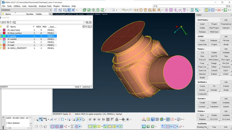
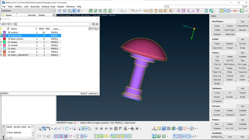
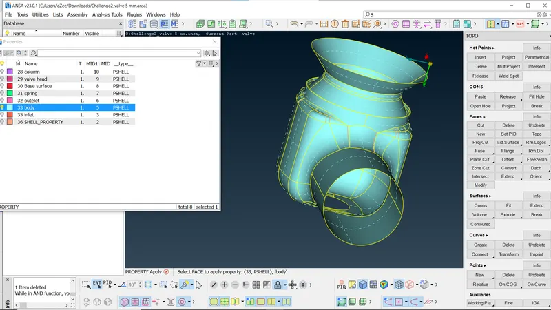
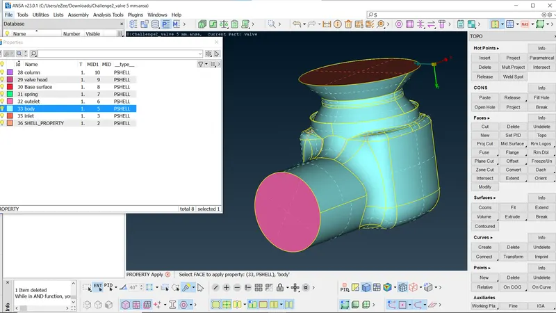
2. Now all PID's assigned. we again checks for geometry. For meshing our first target length is 5 mm. select mesh surface. Go to perimeter and click on length. select the perimeter. select the object by cross box selection. middle click. then give target length as 5mm. middle click. same way give macros lenghth as 5 mm.
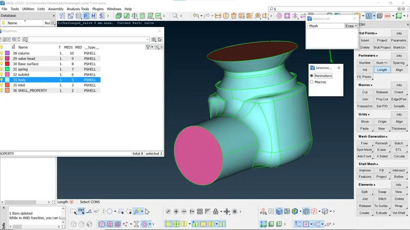
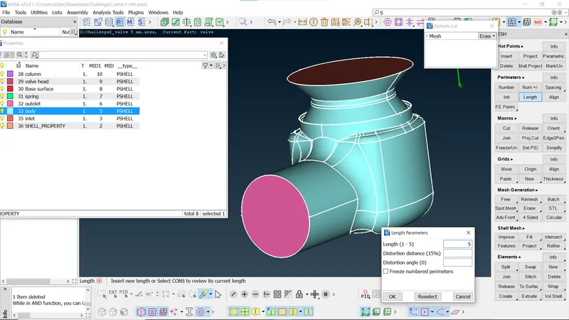
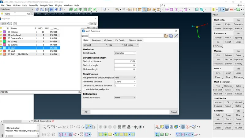
3. Go to Mesh parameter. give target length as 5 mm. and element type should be Tria.
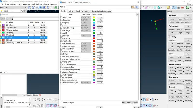
4. Go to quality parameter give target length as 5mm, min=3 and max= 7mm.
5. Go to spot mesh. click on it. Using ENT method assign mesh to each component or we can direcltly assign the mesh for whole budy using PID method.
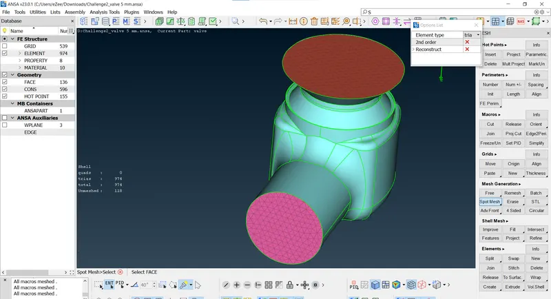
Final mesh model.
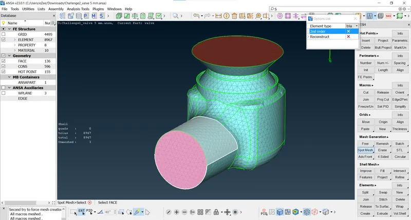
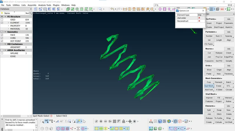
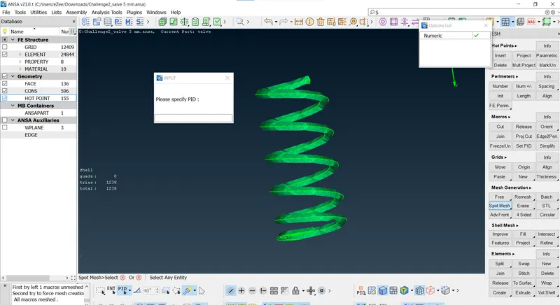
Meshing quality of spring is not good as target lenth is 5mm and component is small.
Target length 3 mm final mesh:-
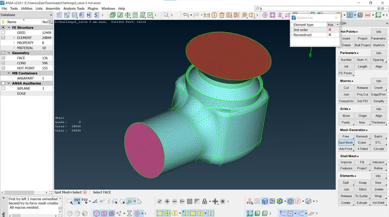
In 3 mm length mesh spring mesh quality is increased. also the number of trai elements also increased.
Target length 1.mm final mesh:-
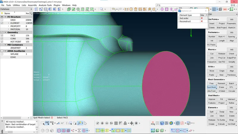
Result:- 3 mm and 1 mm ltarget length mesh having good meshing quality. The conclusion is quality of mesh depends upon the target length. If the target length is small number of elementswill be maximum and Quality of mesh is better.