Week 3 Challenge : CFD meshing on Turbocharger
CFD MESHING ON TURBOCHARGER
OBJECTIVE:
To Check for the geometrical errors to make appropriate volumes.
To Create and assign PIDs as shown in the video.
To Perform surface mesh with the given target lengths as per PIDs.
- Blade stage-1 = 1 mm
- Blade stage-2 = 1 mm
- Impeller = 2 mm
- Shaft rotor = 1 mm
- Turbo casing = 5 mm
- Compressor casing = 5 mm
- Inlet casing cover = 5 mm
PROCEDURE:
1) GEOMETRICAL CLEANUP
Open the given Pressure Valve Model into the ANSA application.
Make sure Cross Hatches should be ON, Drawing Mode should be PID and Module should be TOPO.
Before Meshing we have to clean up the geometry of the Given turbocharger Model
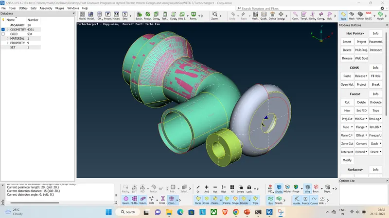
After opening the model in the ANSA software, it looks like some glitches present on the model. we have to do proper geometrical clean-ups on the model.
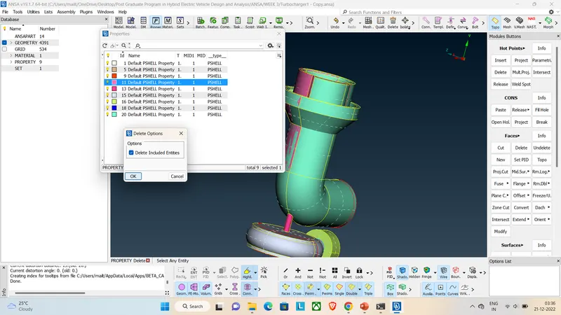
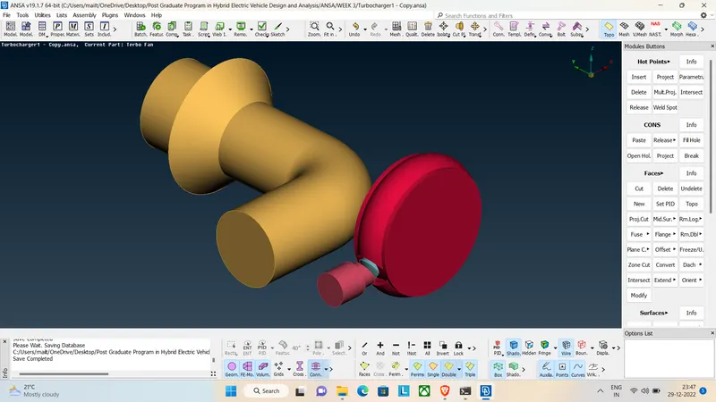
The pink colour surface makes the glitches over the model so we have to remove the surface by simply deleting the corresponding PID of the pink colour surface. now the model looks like there are no more glitches but some open portions present over the model (The model should be free from open portions during the meshing process)
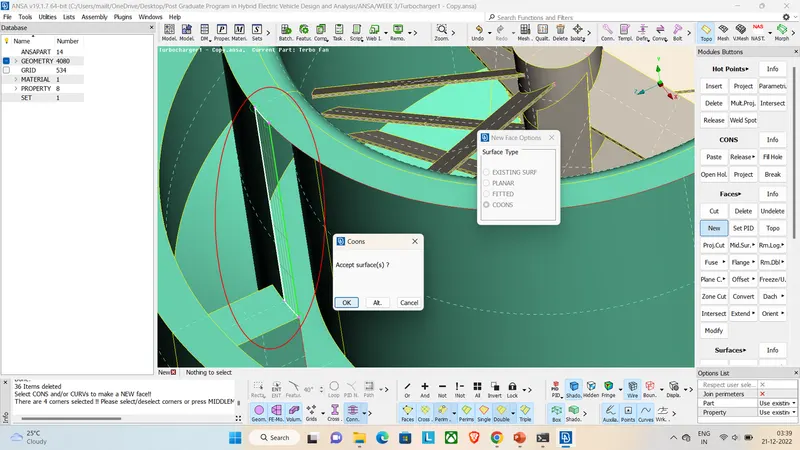
The above pictures show some open portion we have found out after deleting the pink surface, In this case we cannot directly create the new surface over the complex open portion so we have to create Hotpoints manually and project this Hotpoints to opposite cons then only we have to create the new surface by using this Hotpoints. (Refer the Red Marked area in the above picture)
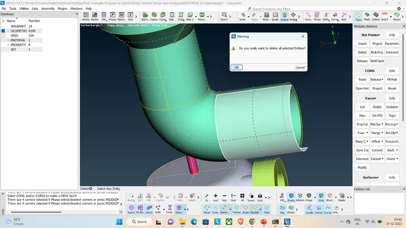
The above picture shows some portion needs to be trimmed because small portion of the surface extended there. for that we have to delete the surface by using universal delete option and create the new surface over there.
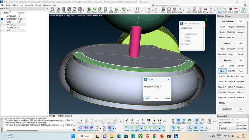
This one also another type of circular opening portion. we cannot create new surface using normal methods. we have to create Hot points over the circular portion of the cons then only we can make the surface by using this cons.
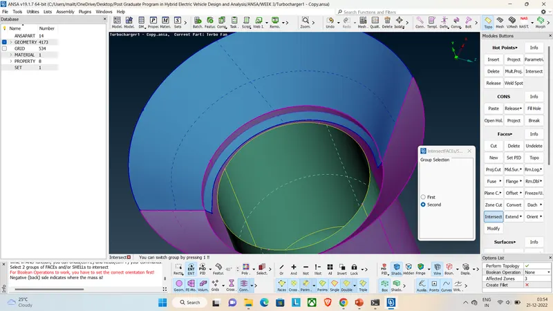
In the above case Two surfaces intersected with each other's so we have to delete the unwanted portion of the surface. by using Intersect option in the faces module we have to separate the intersected portion then easily we can delete the unwanted portion.
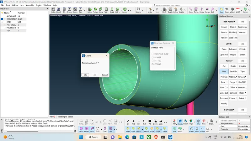
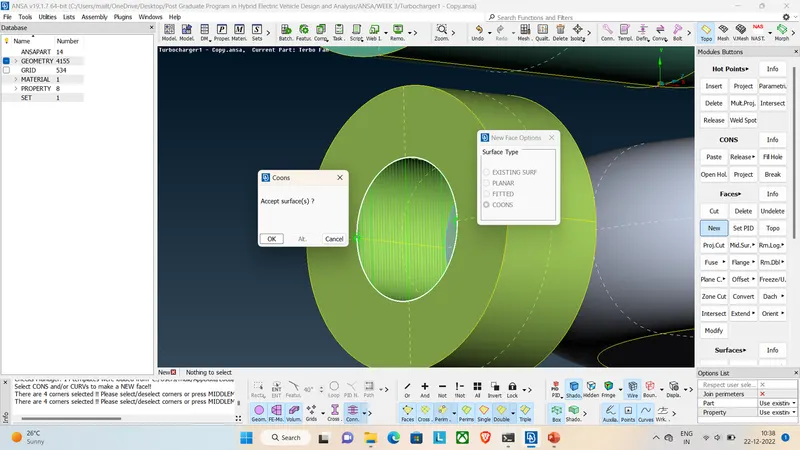
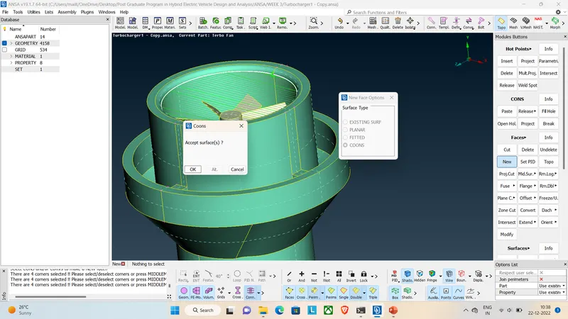
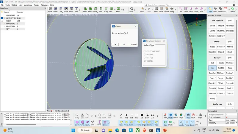
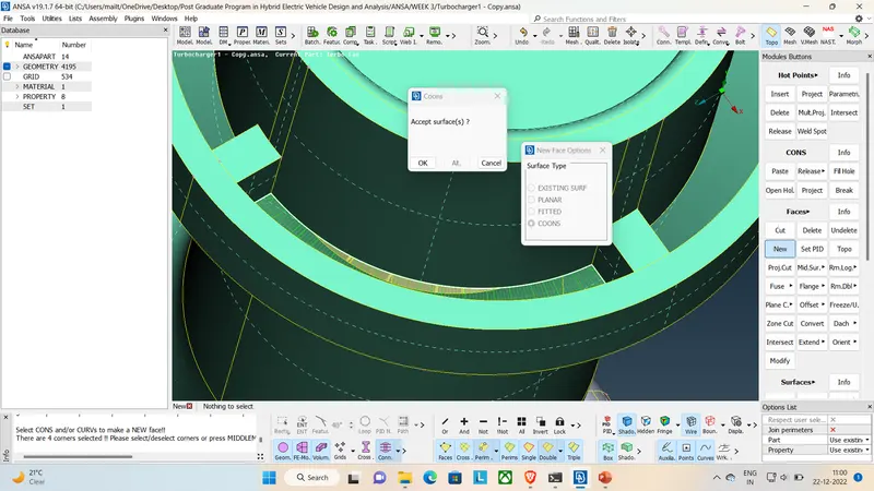
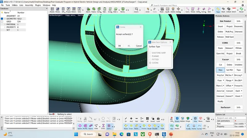
The above six pictures show the normal opening in the various positions and they all closed by normal new surface option or fill hole option.
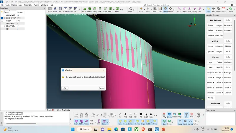
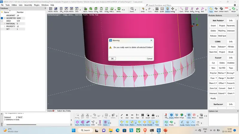
The overlap portions between the thickness portion of the turbocharger casing and the shaft shown in the above two pictures. This must be removed and to avoid single cons we have to project the cons in the shaft to turbocharger casing. Then we have to release the projected cons and Do Topo the Released cons. This will avoid the formation of the single cons over surface and make it triple cons. (Single cons not allowed during meshing but Triple cons allowed) similarly the shaft and the Blade Stage 1 & 2 have some overlap portion this can be solved by the same above method. (Images not included).
Another important thing is to assign all the Turbocharger components to its owns PIDs or New created PIDs. Unwanted PIDs should be removed or deleted.
Now we have 11 PIDs they are as follows,
- Blade Stage-1
- Blade Stage-2
- Shaft Rotor
- Turbo casing
- Inlet Casing Cover
- Impeller
- Bottom Casing Inlet
- Compressor Casing
- Casing Outlet
- Bottom Casing Outlet
- Casing Inlet
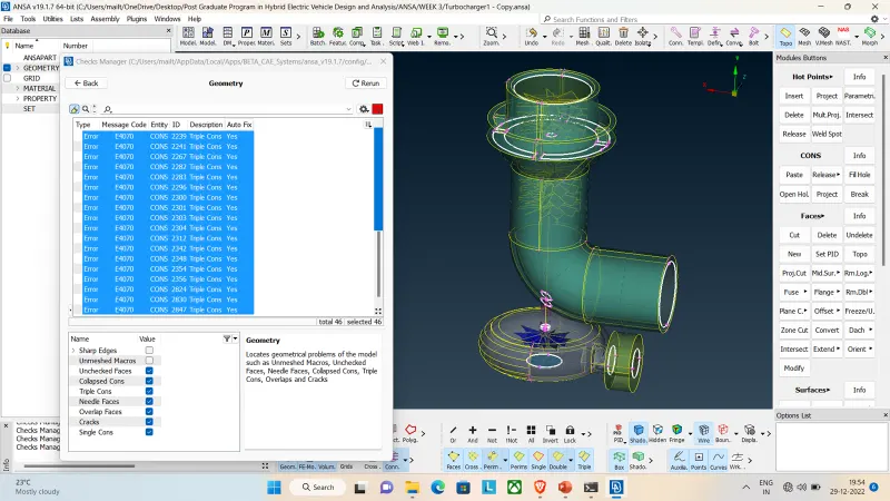
Now we almost done geometrical clean-up. Then we have to check for errors. the above pictures show there are some triple cons identified but they are not issues. so, we can now continue to Surface meshing.
2) SURFACE MESHING:
After we have completed all the geometrical clean-ups we can now do Surface Meshing.
Now we can perform surface mesh with the given target lengths as per PIDs.
- Blade stage-1 = 1 mm
- Blade stage-2 = 1 mm
- Impeller = 2 mm
- Shaft rotor = 1 mm
- Turbo casing = 5 mm
- Compressor casing = 5 mm
- Inlet casing cover = 5 mm
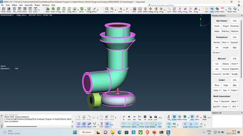
When we meshing, we have to make sure that meshing parameters, Quality Parameters are as per the below details. The details are given PID wise as follows,
- Blade stage-1 = Target length =1 mm, Min=0.5mm, Max=2mm,
- Blade stage-2 = Target length =1 mm, Min=0.5mm, Max=2mm,
- Impeller = Target length =2 mm, Min=1mm, Max=3mm,
- Shaft rotor = Target length =1 mm, Min=0.5mm, Max=2mm,
- Turbo casing = Target length =5 mm, Min=3mm, Max=7mm,
- Compressor casing = 5 mm, Min=3mm, Max=7mm,
- Inlet casing cover = 5 mm, Min=3mm, Max=7mm,
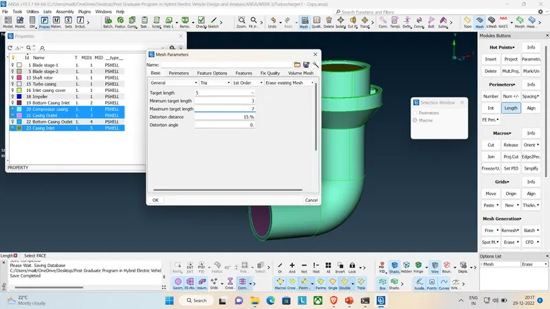
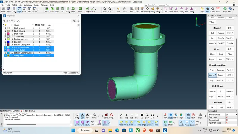
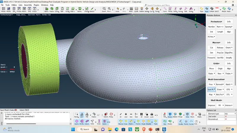
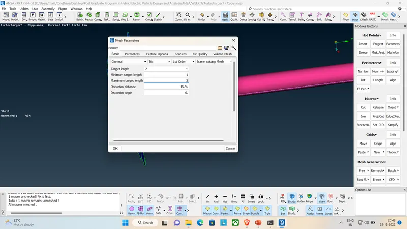
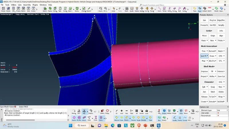
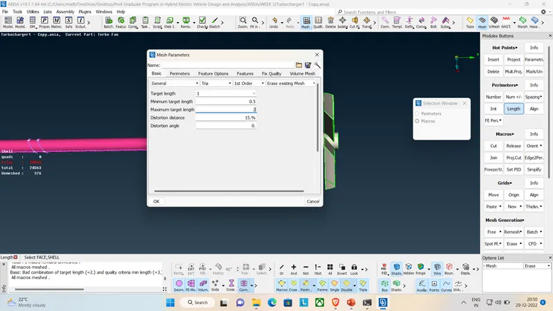
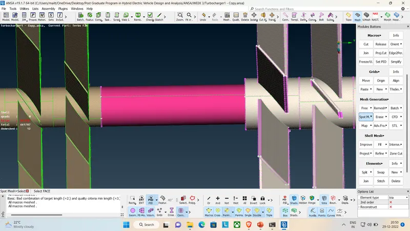
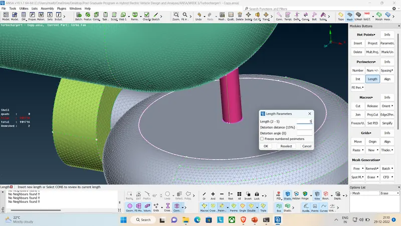
The normal Meshing Shown in the above Seven pictures. In normal Meshing we have to give length perimeters value and macro value of the surface. then we can do spot mesh on the selected PID as per the given Value.
However we done normal meshing there are some cases we cannot perform normal meshing.
These are referred in the below images,
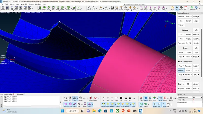
The above Picture shows there is some mesh got deleted after the surface meshing.
This is mainly because of the dissimilar mesh macro length of the two component PIDs. Here first we did mesh on the blue colour object (Impaler). as per the table Target Length =2mm but the pink colour component (Shaft Rotor) as per the table target length =1mm. that's why the macro parameters of the mesh (size of the mesh) not connected the two objects.
So, when we mesh this type of Dissimilar target length, after meshing of the first component do not change or give the macro value for the second component. refer the below images,
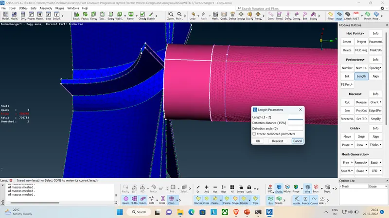
Here we should avoid giving value to the macro parameters (That should be 1~2 - first object - 2mm target and second object - 1mm target)
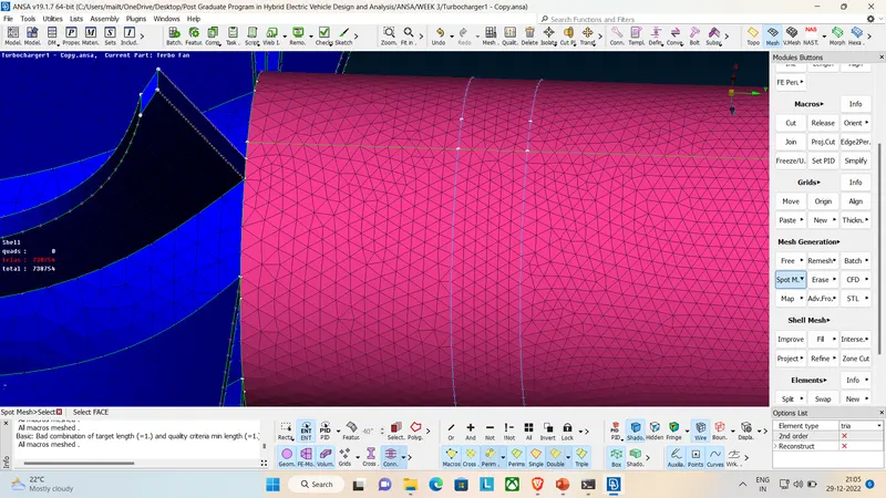
Now we have got all the portions Meshed. same case applicable for the turbo casing also. Turbo casing pictures are as below,
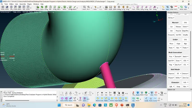
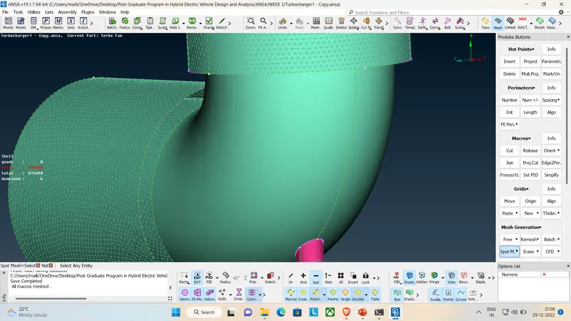
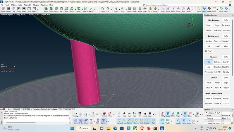
After we completed the meshing, me have to cut the macros like the below picture,
3) VOLUMETRIC MESHING:
After Saving previous works now we can perform Volumetric meshing,
To perform this operation, we have to enter the Volume Mesh Module.
Here in the Volumes -> go to Define -> Auto detect (now new small window will popup, here select the Whole Database)
It will perform the auto detect operation and gives you a list of Volumes available in the given Module.
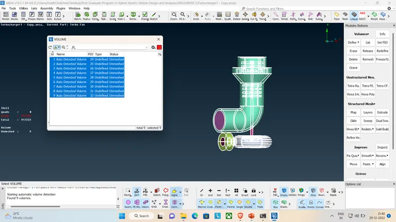
Here totally Nine Volumes have been detected. We don't need all of them. We need only the volumes to be the fluid will flow. so, we need to delete un wanted volumes by simply select the volume from the list and right click the mouse then delete (appear in the right click option).
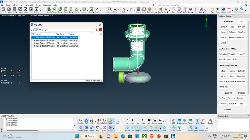
Now we have only Four Volumes that the fluid will flow. Their status also unmeshed. so we have to select the volume from the list and right click (option will appear) -> Remesh (small popup will appear) ->select Tetra CFD ->ok. Now the software will start to do Volume Mesh.
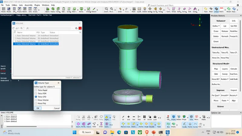
While Volume Meshing, we have to start from small Volumes.
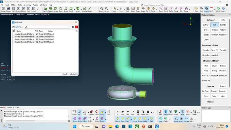
Now we can see the meshing status from the volume list (It will be type-tetra, status-meshed).
And check the below images after volume meshing completed. (For some representation how actually, they are inside).
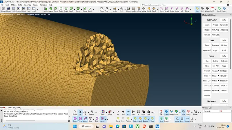
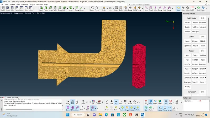
LEARNING OUTCOMES:
Usage of Hot points, Cons Projections, universal delete
Usage of face cut and Intersect
Usage of PShell (Create and Delete PShell, Assign entity to PShell)
Usage of Release and Topo
Usage of Fine option
Usage of length perimeters and macros
Usage of Spot mesh
Usage of Macros cut
Usage of Volume mesh (Define, Auto detect, whole database and visible, list of volumes, Remesh, Tetra CFD)
RESULT:
Thus, the required Target length and mesh length has been applied on the given Turbocharger model as per the given PID parameters.
CONCLUSION:
The Surface Meshing and Volumetric Meshing of the given Turbocharger model has been achieved using ANSA Pre-processor.