Week 3 Challenge : CFD meshing on Turbocharger
Aim: Volumetric mesh of the turbocharger
Procedure:
Before volumetric analysis there is need to check geometry and intersection errors.
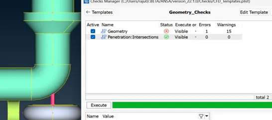
For Geometry check- check manager -select (geometry + intersection) – execute
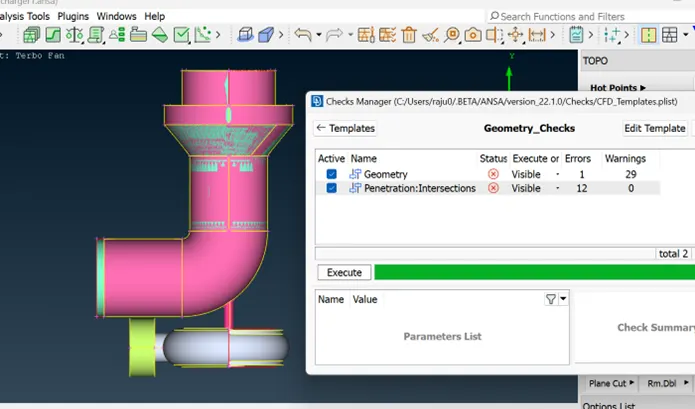
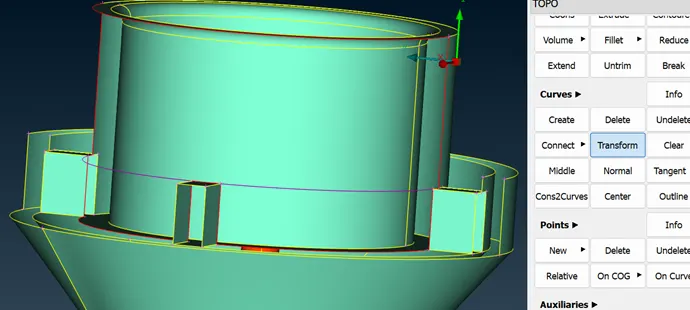
filling all errors of single cons surfaces using different options like
topo-faces-new-cons & fitted (or) Topo-cons-fill holes or curve transform- cons loop – create surface
delete/ create – unwanted/requires- faces.
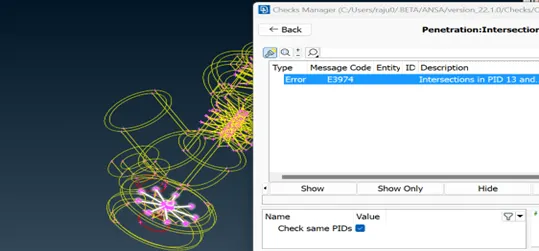
Use- intersection – select- first and second surfaces to create intersect face
Remove- patches/ glitched surfaces from PID option
For intersection errors- check manager -select (geometry + intersection) – execute
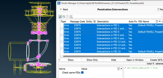
To isolate the intersect part of the shaft- create – triple cones – to create surface – repeat the procedure at required places.
Remove the triple cones and extra faces to maintain as single volume at blade stage 1 and blade stage 2- at extended face of shaft also.
Again check for the intersection errors and do the same procedure to isolate and remove the intersect part. Remove the unwanted hot points and hit top for geometry clearness
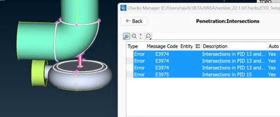
The extra face at and intersected shaft at impeller also delete and use cons transform to delete the single con errors and hit topo. Extra surface at turbine casing also deleted.
For volumetric analysis:
We are performing internal flow analysis, so we have to close the all opening in the component.
After that as per the given question the different mesh sizes has to provide for the each part of turbocharger.
Allocate the PID for each component like blade stage1, blade stage 2, turbine casing, compressor casing, inlet casing, impeller, shaft.
By using not PID – highlight – shaft , blade stage 1&2 for 1 mm meshing – volume mesh- define- remove external volumes – ok
Set perimeter length – max & min as 1.4&0.6 mm – ok – volume mesh – use tetra cfd – mesh -ok – goto mesh generation cfd- visible- freeze mesh.
Repeat the same procedure – for impeller- with perimeter length mix and min (2.3&1.6mm)- ok
For turbine casing, inlet casing and compressor casing- repeat same procedure with perimeter length mix and min (5.5&4.7 mm) – ok – generate mesh – freeze .
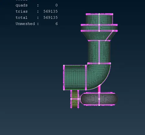
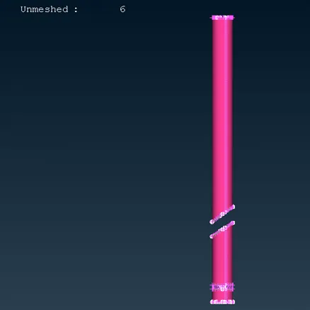
Enable all PID and unfreeze and check the component weather meshed properly or not with the cross section.
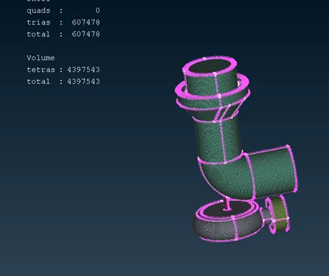
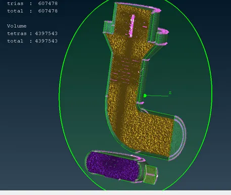
Results & Conclusion:
All the single con error are removed using surface error method by replacing surfaces with different methods. All the intersection errors are removed.
All intersected errors are removed carefully.
One triple con error is considered which is not negotiable. Total 607478 trais were generated after mesh generation.
Total of 4397543 trais were generated after volumetric mesh generation.
Learning outcomes:
During the geometry check new procedures with curve transform and copy with 3 points were learned. How to isolate and delete intersected part and faces with different approaches were learned. Allocate and compress PID, in mesh generation freeze should provide after conducting mesh after each part , otherwise after enable complete part the mesh was get confused at the junction of different mesh given to the components in turbo charger.