Week 3 Challenge : CFD meshing on Turbocharger
AIM: Volumetric Meshing for the required Volumes of a Model of Turbocharger using Ansa.
OBJECTIVE:
Perform surface mesh with the given target lengths as per PIDs.
- Blade stage-1 = 1 mm
- Blade stage-2 = 1 mm
- Impeller = 2 mm
- Shaft rotor = 1 mm
- Turbo casing = 5 mm
- Compressor casing = 5 mm
- Inlet casing cover = 5 mm
THEORY:
Turbocharger:
A turbocharger (technically a turbosupercharger), colloquially known as turbo, is a turbine-driven, forced induction device that increases an internal combustion engine's power output by forcing extra compressed air into the combustion chamber. This improvement over a naturally aspirated engine's power output is because the compressor can force more air—and proportionately more fuel—into the combustion chamber than atmospheric pressure (and for that matter, ram air intakes) alone.
Manufacturers commonly use turbochargers in trucks, cars, trains, aircraft, and construction-equipment engines. They are most often used with Otto cycle and diesel cycle internal combustion engines.
Turbocharger construction and flow of gases
A turbocharger consists of a compressor wheel and exhaust gas turbine wheel coupled together by a solid shaft and that is used to boost the intake air pressure of an internal combustion engine. The exhaust gas turbine extracts energy from the exhaust gas and uses it to drive the compressor and overcome friction. In most automotive-type applications, both the compressor and turbine wheel are of the radial flow type. Some applications, such as medium- and low- speed diesel engines, can use an axial flow turbine wheel instead of a radial flow turbine. The flow of gases through a typical turbocharger with radial flow compressor and turbine wheels
Volumetric Meshing using ANSA:-
METHODOLOGY:-
- Topology Clean up
- Surface Meshing
- Volumetric Meshing
- Topology clean up:-
first we have to import Geometry
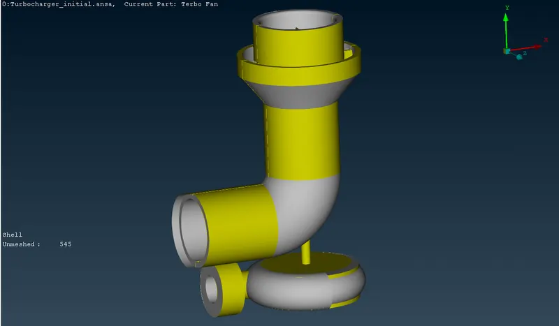
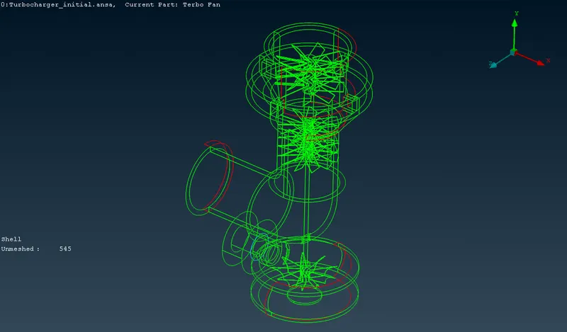
Switching to wireframe view,
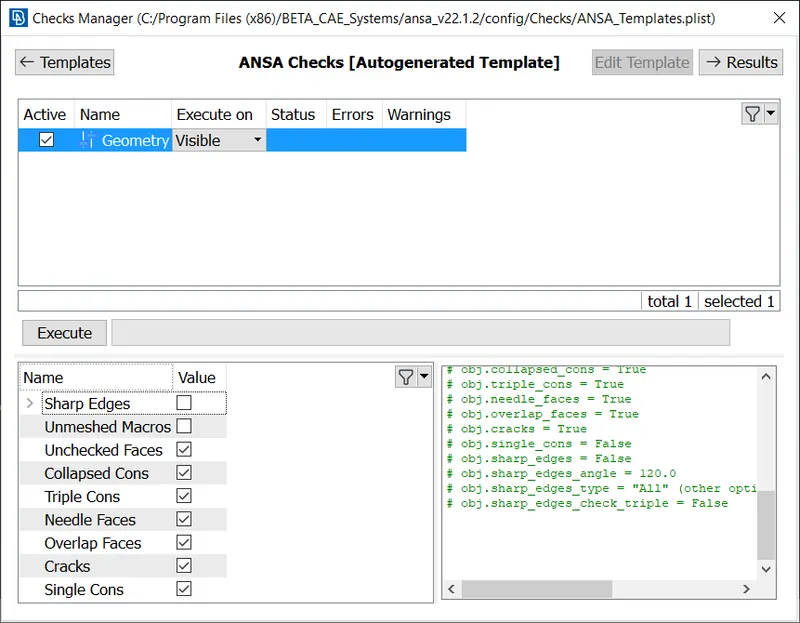
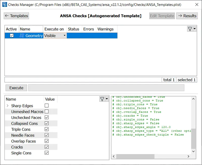
The geometry is checked using ANSA's inbuilt Geometry Checker tool, this is done by going to: Checks -> Geometry
The default checks are chosen, and the following errors are checked. The checking process is started by clicking the Excecute button.
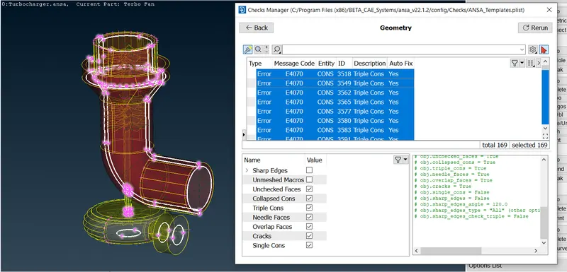
Upon execution, these errors were found:
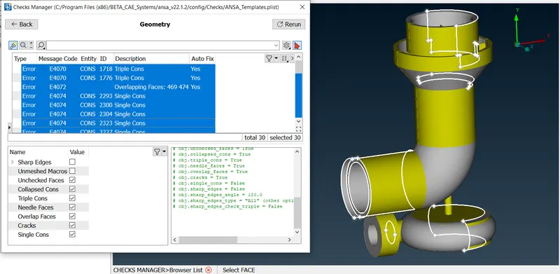
Upon further inspection, the errors are primarily of three types: single CONS, overlapped surfaces and extra surfaces.
These errors were rectified using the TOPO sidebar and all single CONS were removed.
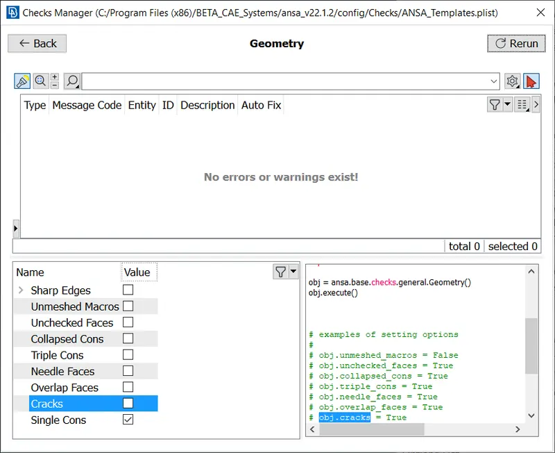
After all issues were fixed, the geometry checking tool was run again to only find these errors:
The results of the geometry checking tool are below:
The triple cons may seem like a serious error at first, but as seen from its location in the geometry, the triple cons are necessary to completely close the volume so that CFD meshing and simulations can be performed with the extrated volume.
No single CONS were found:
These are the double CONS:
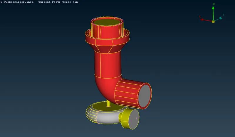
These are the triple CONS (in blue):
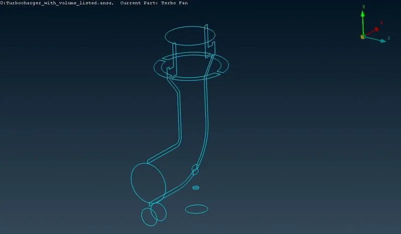
Creation of PIDs: PIDs are user-defined selections of geometry, commonly used to designate sub-parts of the geometry. Such as wheels, body, door, rear wings, etc. in a car. They are used to generate PID specific meshes, with different mesh properties for each PID.
The PIDs are created by going to Properties -> RightClick/New -> PSHELL -> PSHELL
PIDs are created and the geometry is selected using multiple tools available in ANSA, such as ENT selection, PID_Region selection, lock, not, !not and or.
All the following parts of the turbocharger were assigned a PID:
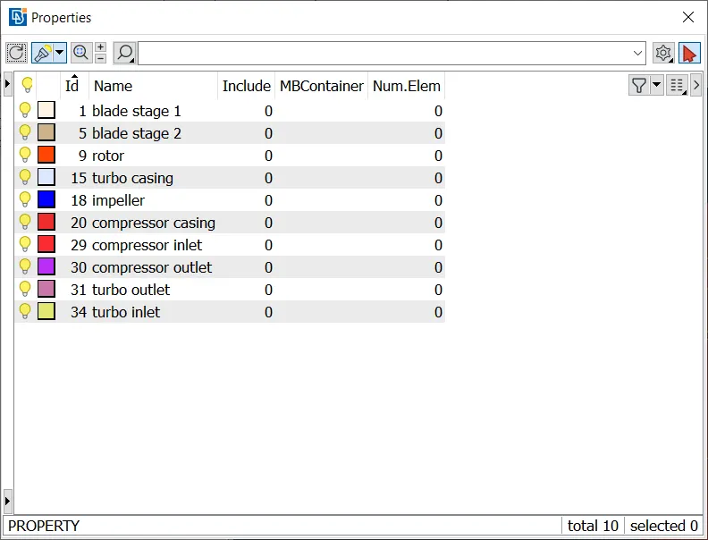
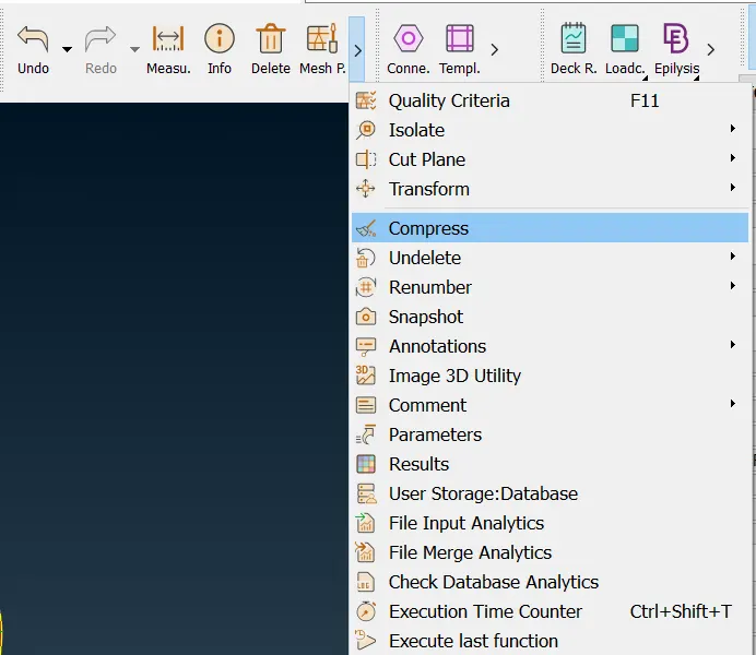
The empty PIDs with the default names were removed by going to: Compress -> Ok
Surface Meshing
The preproccesing to the actual meshing process is complete. The surface mesh will be generated first under Classic Mesh Model. The PIDs were grouped by mesh size. For each size: perimeters, macros, mesh parameters and quality criterion were defined as follow. The mesh is generated for the following parameters using the spot mesh, this is done by going to Mesh Generation -> Spot Mesh -> Visible
Mesh Size: 1mm
Parts of geometry/PID:Â blade stage 1, blade stage 2 and rotor
Go to Perimeters -> Length -> Perimeters, the whole geometry can be selected with the box select tool. After selection, the middle mouse button is pressed and mesh length (1mm) is entered.
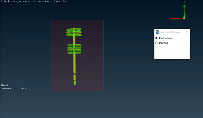
Entering mesh length in mm.
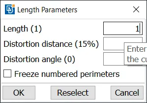
The same process is repeated for Macros as well.
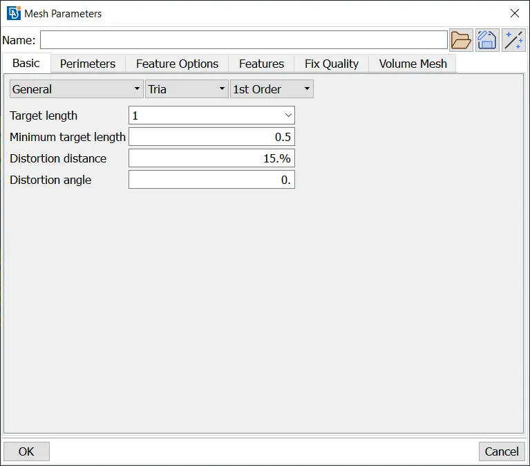
This is where the quality of mesh will be defined, this is done by going to: Mesh Parameters. The target length is entered as 1 and the element type is set to Tria.
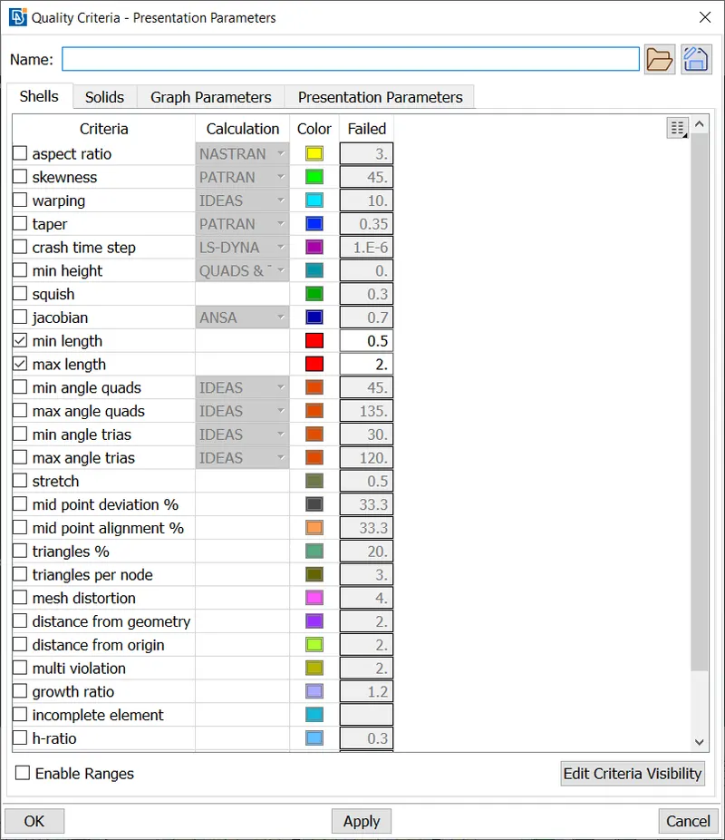
The quality of the mesh is defined in this step, this is done by going to Quality Criteria
Mesh Size: 2mm
Parts of geometry/PID:Â
Go to Perimeters -> Length -> Perimeters, the whole geometry can be selected with the box select tool. After selection, the middle mouse button is pressed and mesh length (2mm) is entered.
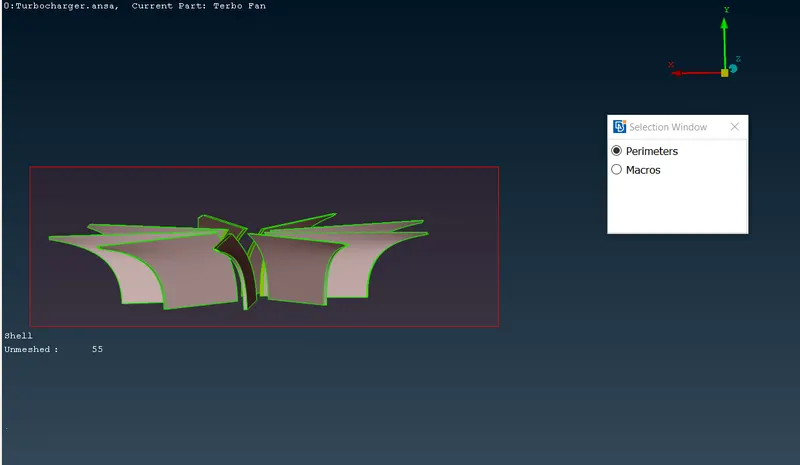
Entering mesh length in mm.
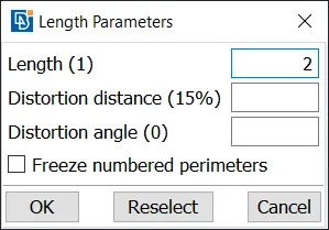
The same process is repeated for Macros as well.
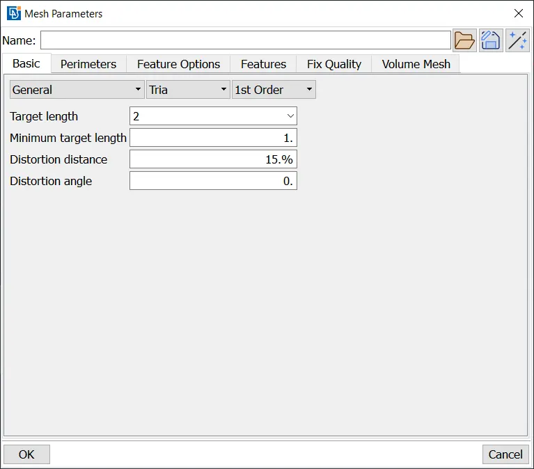
This is where the quality of mesh will be defined, this is done by going to: Mesh Parameters. The target length is entered as 2 and the element type is set to Tria.
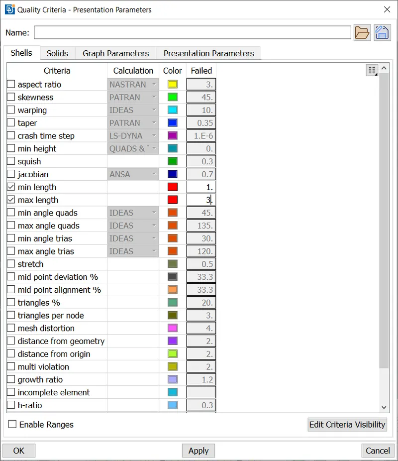
The quality of the mesh is defined in this step, this is done by going to Quality Criteria
Mesh Size: 5mm
Parts of geometry/PID:Â
Go to Perimeters -> Length -> Perimeters, the whole geometry can be selected with the box select tool. After selection, the middle mouse button is pressed and mesh length (5mm) is entered.
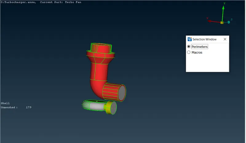
Entering mesh length in mm.
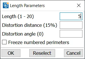
The same process is repeated for Macros as well.
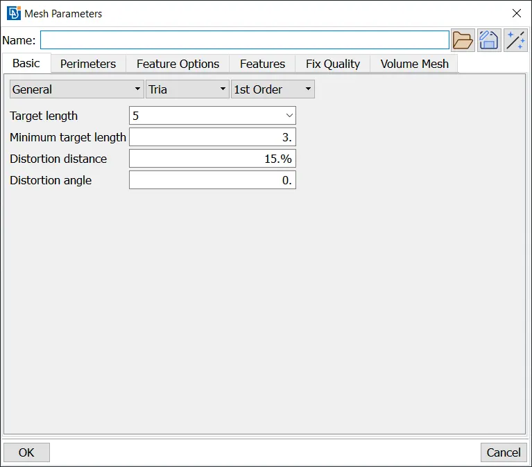
This is where the quality of mesh will be defined, this is done by going to: Mesh Parameters. The target length is entered as 5 and the element type is set to Tria.
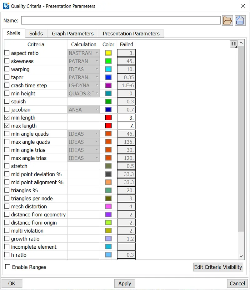
The quality of the mesh is defined in this step, this is done by going to Quality Criteria
Â
Regions where two different mesh sizes interact were not meshed using the above steps, hence they had to be remeshed using the same settings but without defining the length of the mesh for perimeters and macros. (Perimeters -> Length -> Perimeters)
Â
Volumetric Meshing
The surface mesh has been generated, now the volume mesh has to be generated.
Go to V.Mesh tab,
Volumes -> Define ->
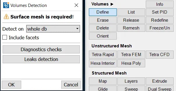
Click on OK, and ANSA will generate volumes automatically. These are the autogenerated volumes:
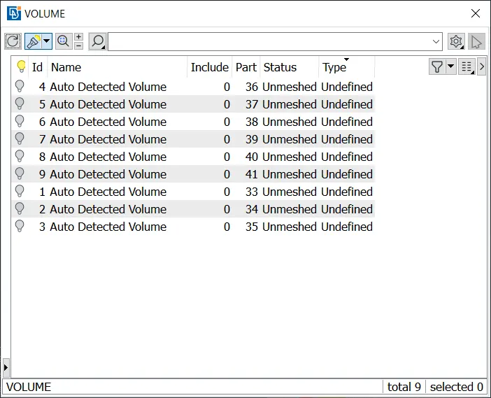
Click on each volume and view its preview, the required volumes (volumes where fluid flow will occur) are renamed and the other volumes are deleted.
After deletion, these volumes remain:
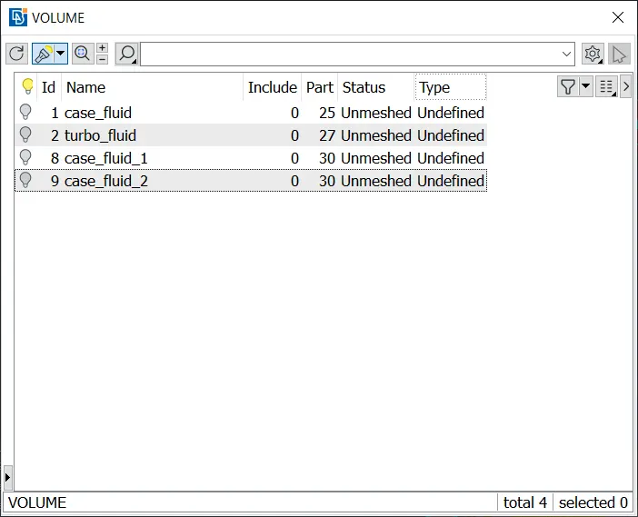
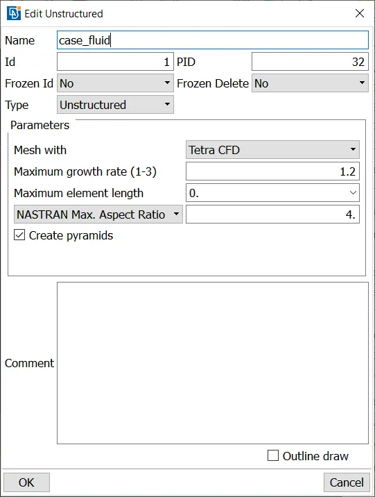
Double click on each volume and change "Mesh with" to Tetra CFD. Tetra is the shape of the mesh's elements and CFD is the application.
Right click on each volume and click Remesh, this will mesh the volume with the selected element type (Tetra CFD)
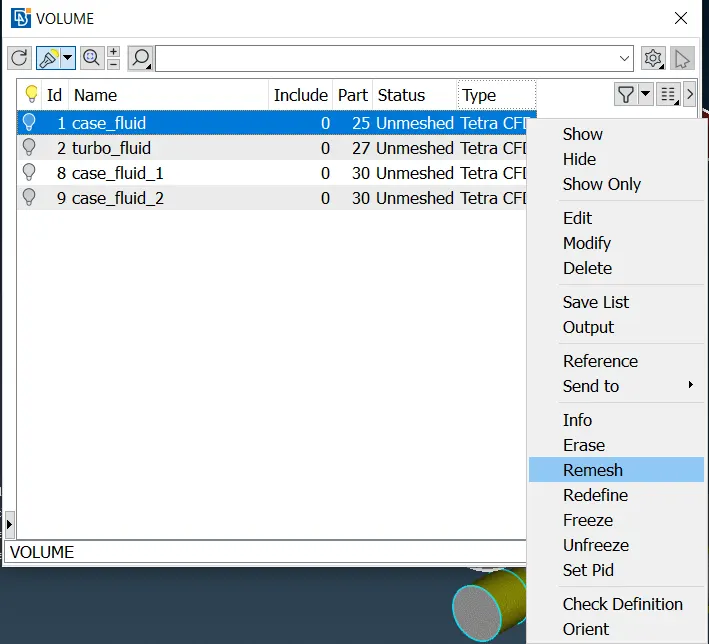
This process may take a while to complete, and ANSA may not respond.
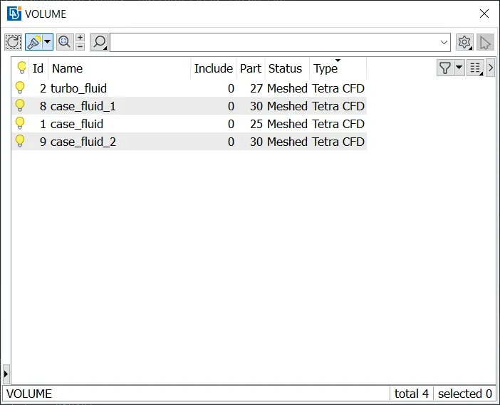
After all volumes are meshed, this is the resulting list of volumes:
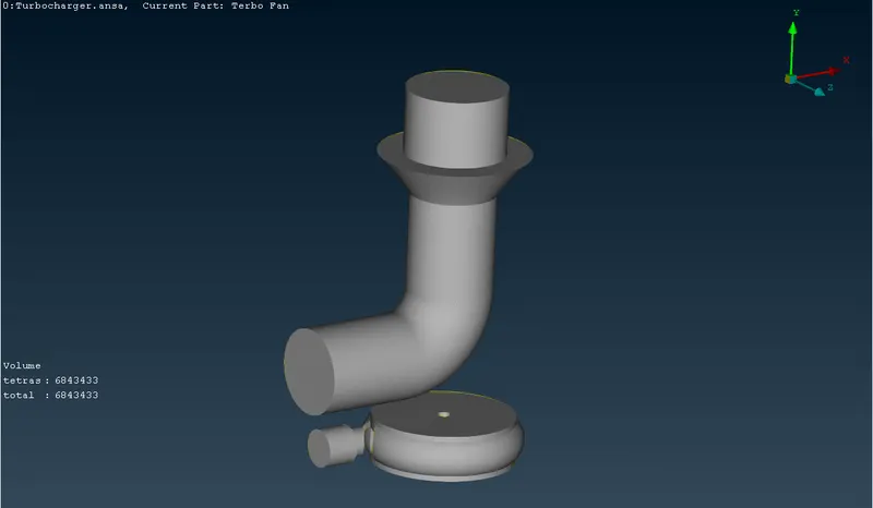
The mesh is ready and can be viewed:
The volumetric mesh contains 6.8 million cells, all of them are tetras.
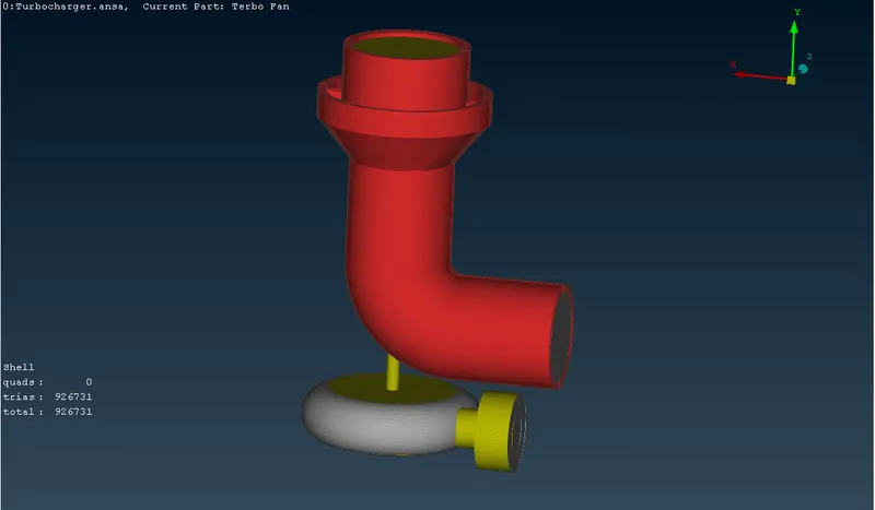
The surface mesh contains 926731 cells, all of them are triads.
Zooming in,
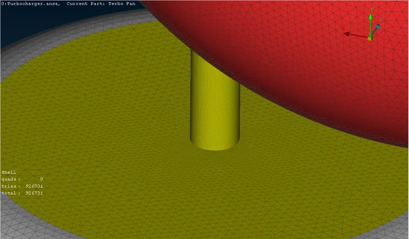
Cross Sectional View
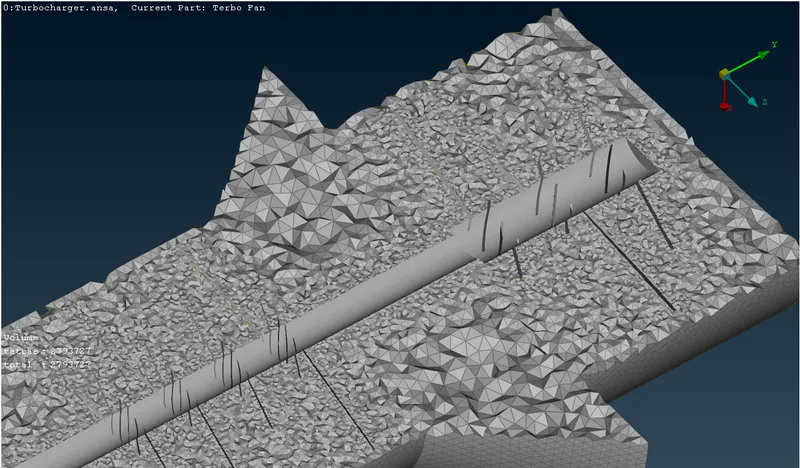
The sizes of the elements are smaller near the blades where the mesh sizing is 1mm, and the mesh elements are larger near the walls of the outer case where the mesh size is 5mm.
Conclusion:
- Geometry Clean up is carried out by removing the all the errors, interfacing components and overlaping components.
- Volumetric Mesh is done by uisng tetrahedral Mesh and using the above picture.
ANSA FILE : https://drive.google.com/file/d/1hf7YgbNWMcluGN_LyHibU2A6Hyi_cSSl/view?usp=sharing