Week 3 Challenge : CFD meshing on Turbocharger
Aim/Objective:
To carry out surface mesh with the given target lengths as PIDS and volumetric mesh for the required volumes of the turbocharger
Procedure:
The turbocharger model needs to undergo topology cleanup, surface meshing and volumetric meshing before it is ready for CFD simulation.
Topology Cleanup/Geometry Cleanup
In this step of the CFD solution, the geometry is made clear of any single cons, triple cons, intersections, overlapping surfaces, and additional surfaces that would make it difficult for volumetric meshing. The regions with single cons are cleared using coons by either projecting new hot points so that the coons option produces a desired surface. The regions were a single con is present due to intersestion of two surfaces is treated using the intersection option under faces and the protruding faces are deleted.
The regions with double-colored glitches are cleaned by deleting PID by region. In this way all the pink overlapping surfaces are deleted. Further the regions in the shaft with triple cons are cleared by deleted unwanted surfaces that would prove to be a hindrance for volumetric meshing. In the shaft, the area where the pink and brown surface is overlapping is cut using the project option under faces, making it easy to delete the pink surface for ease in meshing. The blue region at the end of shaft is treated by using cut option and delete the unwanted blue surface.
Geometry checks for single cons and triple cons were and checked and the necessary actions where taken were triple cons was not necessary and all single cons were removed. The model was closed at all ends to ensure, it was water-tight model that was fit for volumetric meshing Further PIDS were assigned to the different regions and they include
- Blade stage-1
- Blade stage-2
- Impeller
- Shaft rotor
- Turbo casing
- Compressor casing
- Inlet casing cover
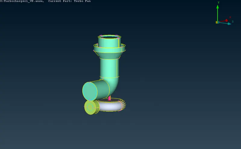
Figure 1. Image of the turbocharger after geometry cleanup
Surface Meshing
In surface meshing, the specific PIDs were meshed according to given target length. Regions with similar surface mesh target length were meshed together. For example the turbo casing, compressor casing, and the inlet casing cover had target length of 5mm so they were meshed together. But it was noticed that after meshing certain regions other meshes disappeared this was because of the sudden changes in the mesh length. The transition of the target length specially in the connecting regions have to be smooth so the length in macros had to be adjusted so that the mesh didnt disppear and the transition was smooth.
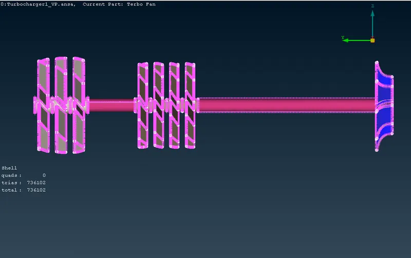
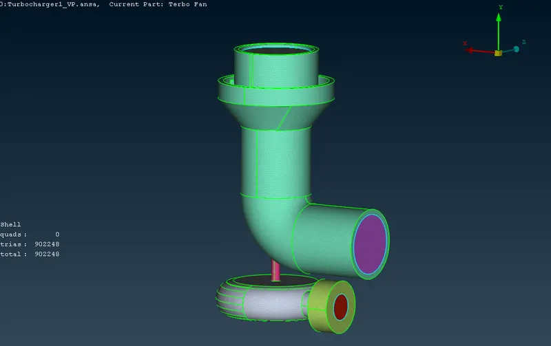
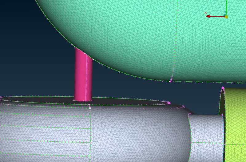
Figure 2. Images illustrating surface mesh on different regions of the turbocharger.
Volumetric Meshing
After completing the surface mesh, the geometry was ready for volumetric mesh. By using the define option, ANSA software automatically generates a list of regions that are good for volumetric mesh. The user has the option to delete the ones that showcase the inner volume and not the volume of the solids. In this way, we end up with 4 regions which are fit for volumetric meshing. By right clicking the region in that list and clicking on Tetra rapid or CFD mesh, the volumetric mesh for each region is created.
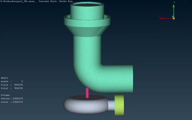
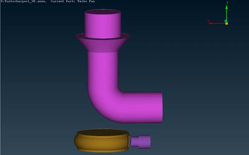
Figure 3. Volumetric mesh of the turbocharger (left), and the inside volume (right)
Learning Outcomes:
From this geometry cleanup, surface meshing and volumetric meshing challenge, it is evident that for a good volumetric mesh, unwanted surfaces needs to be deleted and there should be smooth transition of target length from one PID to the other so that the CFD solution is close to accurate. Further, it is essential to ensure that overlapping surfaces are removed to avoide penetration which can be a problem while carrying out volumetric meshing.
Result:
Surface meshing, No. of elements= 902248
Volumetric meshing, No.of elements = 2908535
Conclusion:
There are several steps to be completed before a good quality volumetric mesh can be achieved. First is geometry cleanup and the next is surface mesh. The number of elements in volumetric mesh will be much larger than in surface mesh.