Week 2 Challenge : Surface meshing on a Pressure valve
Aim/Objective:
To perform the preprocessing steps - geometry cleanup and mesh generation on a pressure valve for three different cases of target length i.e., 1mm, 3mm, and 5 mm using trias as the element type. From the three different cases, the best case is identified.
Procedure:
- Topology Cleanup
The initial step is to clean the geometry for single cons, holes and other irregularities that might create issues while meshing and for CFD simulation. The regions with single cons will be highlighted in red, regions with double cons in yellow, and triple cons in blue. The single cons are filled using coons or fitted or planar as per the geometry. Extra care should be taken while selecting certain surfaces as entities or loop. Faces with same curve length can be selected using loop while the ones with different lengths should be selected via entities to ensure the holes or gaps are covered perfectly.
Once the holes and grooves are cleared, the geometry check should be carried out to see if there are any additional areas that are being missed out before proceeding to the next step that is meshing. Also, areas with very small length, should be combined with other surfaces or cut (which appears in orange) so as to ensure that the mesh generation flow is smooth.
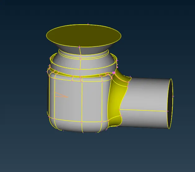
Figure 1. Topology Cleanup of the Pressure Valve.
The next step is to assign PIDS to different parts of the pressure valve which are
1. Body
2. Inlet
3. Outlet
4. Dome
5. Column
6. Base
7. Spring
Once this step is completed we enter into the next step i.e. Meshing
- Mesh Generation
Case I : Target length=5mm
In this case, the target length is chosen as 5mm and trias is selected as the element type. Further under quality criteria, the maximum mesh quality is taken to be 5.5 and minimum as 4.5. Under Perimeter, the length tab is selected and for both perimeters and macros, the length is taken as 5. Now under meshing either spot mesh or CFD mesh is selected and the mesh is generated.
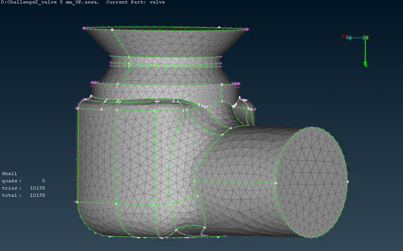
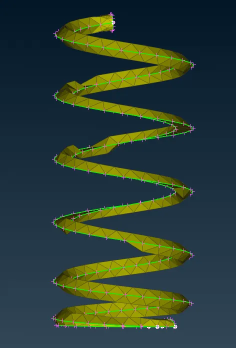
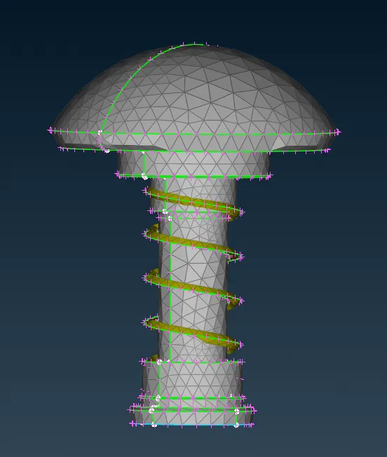
Figure 2. Mesh generated for Pressure Valve with Target Length = 5mm
Case II: Target length=3mm
In this case, the target length is chosen as 3mm and trias is selected as the element type. Further under quality criteria, the maximum mesh quality is taken to be 3.5 and minimum as 2.5. Under Perimeter, the length tab is selected and for both perimeters and macros, the length is taken as 3. Now under meshing, either spot mesh or CFD mesh is selected and the visible regions are meshed by spacing them out.
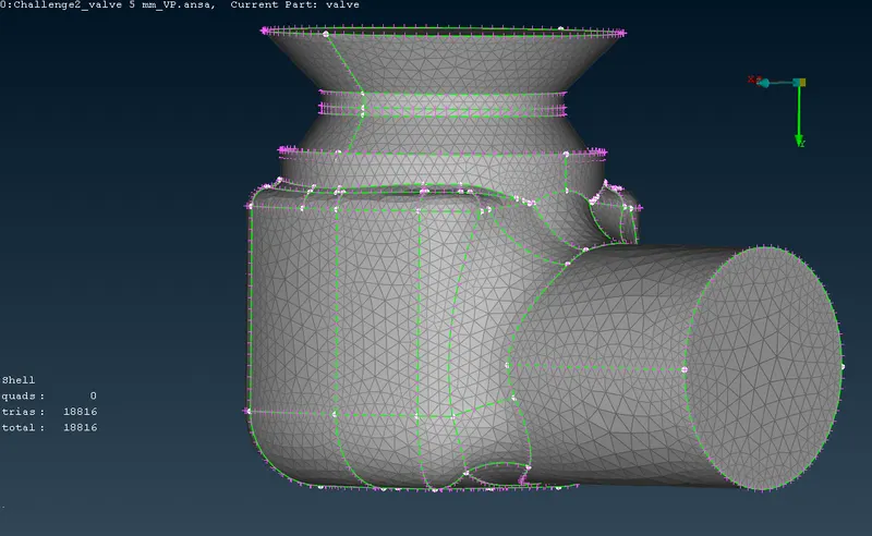
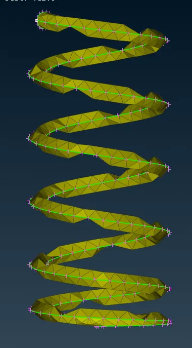
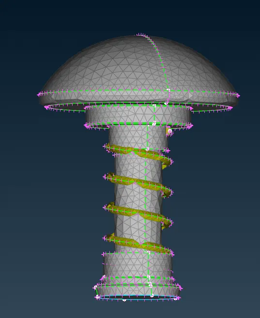
Figure 3. Mesh generated for Pressure Valve with Target Length = 3mm
Case III: Target length=1mm
In this case, the target length is chosen as 1mm and trias is selected as the element type. Further under quality criteria, the maximum mesh quality is taken to be 0.8 and minimum as 1.2. Under Perimeter, the length tab is selected and for both perimeters and macros, the length is taken as 1. Now under meshing either spot mesh or CFD mesh is selected and the visible regions are meshed by spacing them out.
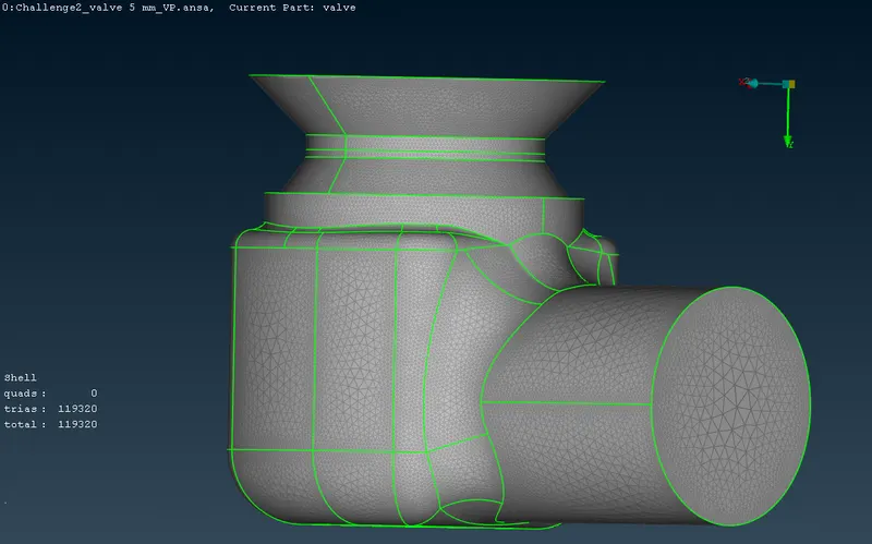
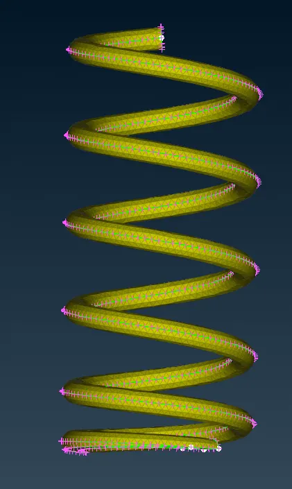
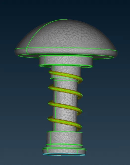
Figure 4. Mesh generated for Pressure Valve with Target Length = 1mm
Learning Outcomes:
From the above three cases with three different target lengths, it is clear that as the target length reduces, the spring surface is captured more neatly and effectively. Further, aligning or spacing the meshing from inside out helps in having finer mesh around the walls where the physics is more complex and needs to be simulated with accuracy. As the target length decreases, the number of elements increases and the time taken for meshing also increases. This is the reason why engineers conduct mesh sensitivity test before opting for very small target lengthto ensure that a balance between resource and accuracy is achieved
Further, a good geometry cleanup and PID naming has helped in easing the meshing process.
Result:
For Case I: Total Elements = 10158
For Case II: Total Elements = 18816
For Case II: Total Elements = 119320
Conclusion:
From this challenge, it is evident that the mesh target length should be chosen accurately because it have an impact on the final CFD solution. Moreover, the geometry clean up should be carried out effectively to allow easy meshing process.