Week 3 Challenge : CFD meshing on Turbocharger
Aim: CFD Meshing on Turbocharger
Procedure:
Correcting the geometry and removing overlapped surfaces
- Open the model in ANSA.
- Check for errors using Checks>Geometry. Select ANSA Check from the dialog box and select the following checkboxes: Unchecked Faces, Collapsed Cons, Triple Cons, Needle Faces, Overlap Faces, Cracks, and Single Cons.
- Click on execute and check for the geometric errors listed by the software.
- Fix the geometric errors, i.e., remove the Single CONS and unnecessary Triple Cons using NEW function in Faces Section of TOPO Module.
- Use the property dialog box to locate the overlapped surfaces and delete the entities directly.
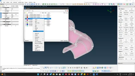
Completing the bottom casing geometry
- Notice that the bottom casing has a hole which can’t be corrected by using the NEW function.
- Here we use parametric function on the smaller edges of the loop to create new hot points there by reducing the size of new surface that we will create next.
- The NEW function is now able to work properly on these smaller sections and we can fill the hole in 8 iterations.
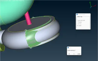
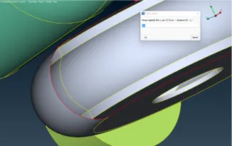
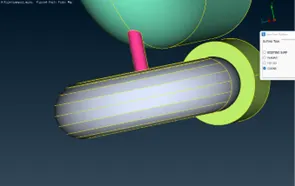
Creating intersect to remove single cons.
- Notice the following geometry in the given model. As we know that a Triple con should be present at the intersection of the 2 surfaces visible here. Although, the surfaces seems to pass through each other.
- To amend this issue, use the INTERSECT function in the FACES section of TOPO module and create an intersection on the line where the two surfaces meet. Using this function, the software is able to define the extensions as separate surfaces.
- Now delete the extensions to remove the Single Cons observed on the extensions as well as remove the Triple Con on the intersection.
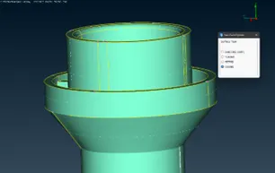
Fixing the single cons at the top of Compressor Casing
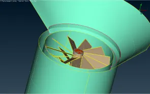
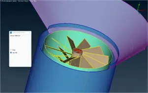
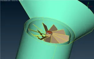
- Notice that the hole can’t be fixed using NEW function, due to the irregularity of the single CONS.
- Use the Project function, in Hot points section, to project the available hot point on the upper single con.
- Now several smaller sections are available for creating new surfaces. Use this smaller sections to fill the hole and remove the single cons.
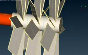
Removing extra surfaces from rotor shaft and creating new cons to fuse the geometrical constructs
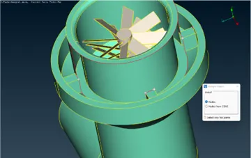
- Hide the outer casing using NOT function.
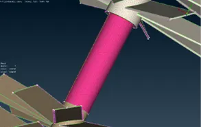
- Notice that there are several triple cons on the rotor shaft. These triple cons represent extra surfaces present at those points. Hide the shaft wall using not option and remove these extra surfaces.
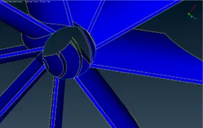
- At the impeller-rotor joint, deleting the intersecting surface removes part of the required geomentry. So, using the Project function in COONS section, create an extra surface on the impeller and remove the intersecting surface. Removing these intersecting surfaces helps in assuming the entire rotor shaft as a single volume which is useful for volumetric mesh.
- Use the same Project option to fuse the rotor geometry with casing geometry at relevant intersection points.
Labelling the PIDs
- Open the properties module from the top toolbar.
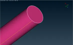
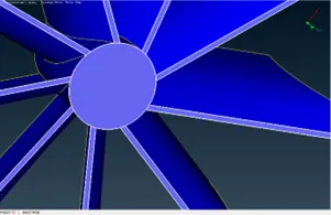
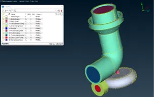
- Create 11 new elements, as shown in the figure below, using Right click>New>PSHELL>PSHELL. Specify the color and name of each element as per requirement.
- Assign the PID to respective parts of the Turbo Compressor as shown below. This will enable in easier selection of parts for meshing.
Meshing the Turbo Compressor surface
- Select the mesh module.
- Click on length function in perimeters.
- Select perimeters>Select model>Set the mesh length.
- Select Macros>Select model>Set the mesh length.
- Select Mesh Parameters from tool bar above set mesh length and select element type as tria.
- Select mesh quality>Activate minimum length and maximum length options> Set them according to your mesh length.
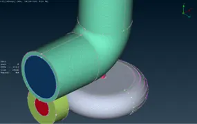
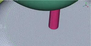
- Using the properties dialog box activate the PIDs one-by-one and use Free mesh>Visible function to mesh the geometries.
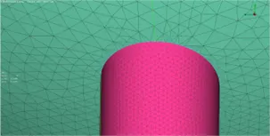
- Repeat the process for other parts of the geometry by changing the mesh length every time.
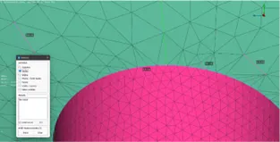
- Remesh the geometries at intersection to remove any discrepancies occurring due to mesh length contradictions.
Deploying Volumetric Mesh
- Go to the volumetric mesh module.
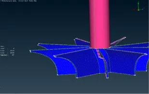
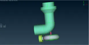
- Enable the Define function and let the software autodetect volume from the whole database of PIDs.
- Hide the volumes related to the thickness of the geometry.
- Now, apply volumetric mesh on the remaining volumes one-by-one using Tetra CFD meshing tool in Unstructured mesh section of Volumetric mesh module.
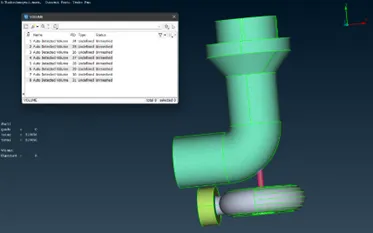
Learning Outcomes: Learn to deploy volumetric mesh. Observe the influence of mesh length on surface mesh deployed at intersection points of rotor-compressor casing, rotor-bottom casing and rotor-impeller.
Result:
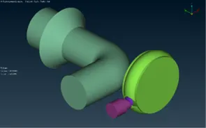
Deployed Surface mesh on the given turbo charger geometry with the following specifications:
- Blade stage-1 = 1 mm
- Blade stage-2 = 1 mm
- Impeller = 2 mm
- Shaft rotor = 1 mm
- Turbo casing = 5 mm
- Compressor casing = 5 mm
- Inlet casing cover = 5 mm
Subsequently, deployed volumetric geometry using Tetra CFD function on the given geometry.
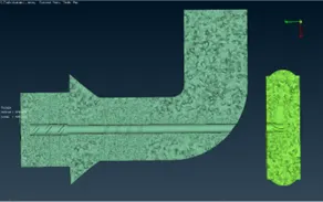
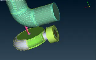
Conclusion: Volumetric mesh was deployed over the provided model of Turbocharger using ANSA.