Project 1 : CFD Meshing for Tesla Cyber Truck
Aim: Deploying Volumetric Mesh on Tesla CyberTruck
Procedure:
Cleaning the Geometry
- Open the given model of Tesla Cybertruck. All the CONS are observed as Single Cons.
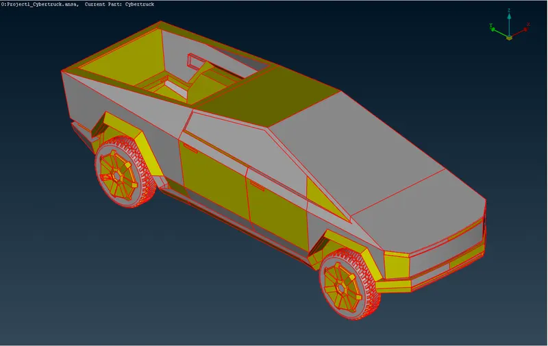
- Perform TOPO on the entire model from TOPO>Faces>Topo.
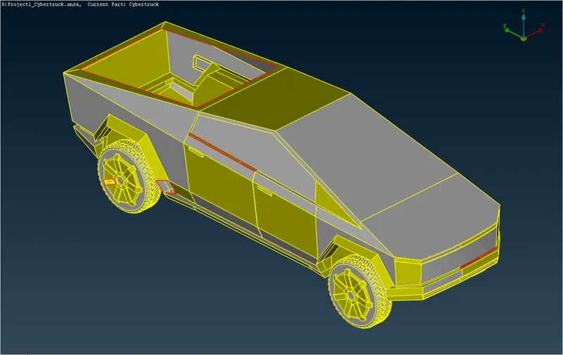
- Several single CONS are still present.
- As the model is symmetric delete half of the model and clean geometry of the other half.
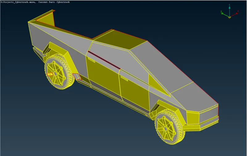
- The model should look like below after clean up.
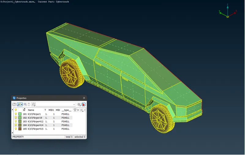
Cleaning the Geometry of tires
- The tires are joined with the body in the model leading to formation of a Triple CONS at the joint.
- Delete these extra surfaces so that the tire and body constitute a single internal volume. This will help us in easy deployment of volumetric mesh at later stage.
Assigning PIDs
- Assign PIDs to various parts of the geometry as defined below:
- Tail Light
- Roof
- Headlight
- Windows and Shield
- Body
- Wheels
This will make our work easier while deploying surface mesh.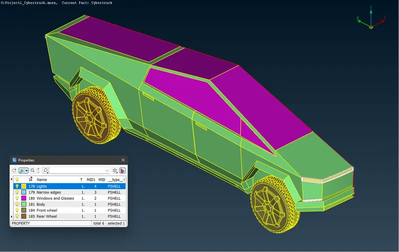
Deploying Surface Mesh
- On the above toolbar open the dropdown menu by clicking on the arrow on the right side of NAS.
- Select OPENFOAM from the dropdown menu.
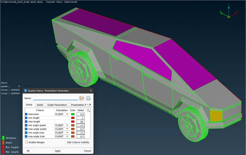
- Open the mesh quality dialog box.
- Click on the edit criteria visibility button and select the following criteria:
- Skewness
- Min length
- Max length
- Angle Shells
- Unselect the other criteria and click on OK.
- Set the Calculation to FLUENT for the relevant criteria seen in the mesh quality dialog box.
- Set the color for all the parameters to easily detect which criteria is failing in the surface mesh. Click on Apply>OK.
- Select entity mode from the lower toolbar and enable hidden view mode.
- Deploy surface mesh on the various PIDs defined above with the given specifications:
PID Target Length Minimum Length Maximum Length Tail Light 4 mm 2 mm 6 mm Roof 11 mm 2 mm 20 mm Headlight 11 mm 2 mm 20 mm Windows and Shield 11 mm 2 mm 20 mm Body 11 mm 2 mm 20 mm Wheels 3 mm 1 mm 5 mm - Deploy the surface mesh on the PIDs by isolating them in the following sequence: Wheels > Tail Light > Roof > Headlight > Windows and Shields > Body
- After deploying mesh on all the surfaces, isolate the body PID>Set the quality criteria and mesh parameters accordingly>Open the Length dialog box from perimeters menu in surface mesh module and select perimeters. Select all the edges which are not shared with Tail Light and Wheels. To accomplish this, select the entire body by clicking the left mouse button and dragging the cursor over the entire geometry. Now enable other PIDs and deselect the perimeters shared with Tail Light and Wheels PIDs. Click on middle mouse button and set length as 3 mm. Set macros length and deploy the mesh using spot mesh>visible. A surface mesh is deployed on the entire body with the mesh length varying along the perimeters shared with other PIDs.
- Fix any other off elements observed in the geometry.
Applying symmetry on the surface meshed model to obtain the complete car
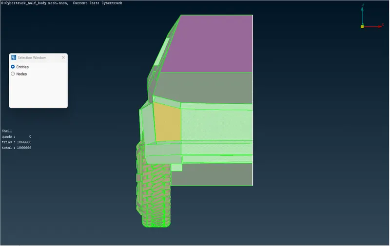
- After successfully deploying the surface mesh, Click on Transform > Copy on the top toolbar.
- Select the entire part of the model that is to be mirrored.
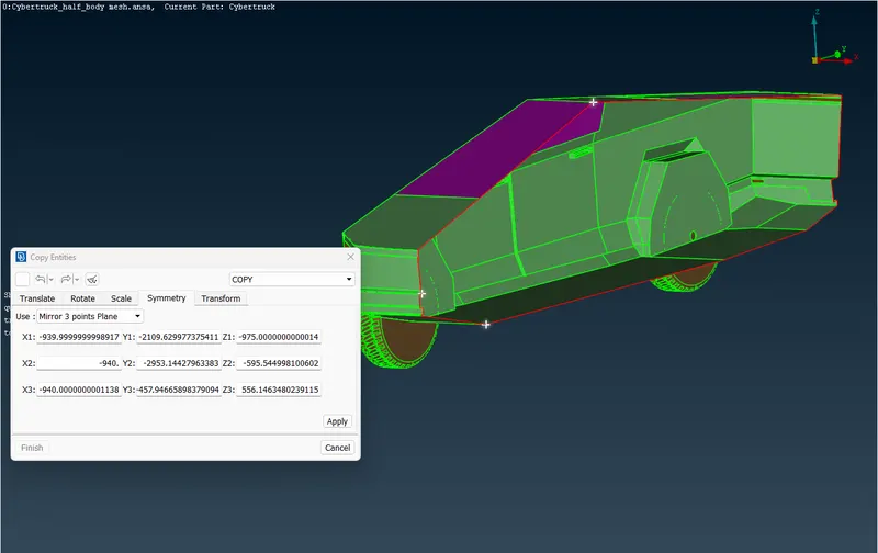
- A dialog box will open. Go to symmetry tab. Set Use to Mirror 3-point plane. Select any 3 random points on the open surface/single cons of the car. The locations of these points are specified in the dialog box. Click on Apply.
- A new dialog box opens. Set PID: No Offset; Part: Same Part; Set: None. Click on OK and then click on Finish after checking the geometry. The entire geometry is now mirrored.
Preparing wind tunnel and deploying surface mesh on the wind tunnel
- To prepare the wind tunnel enable TOPO mode.
- Measure the length of the car which comes to around 5960.77.
- Select “relative” option in Points menu. Select the middle point located at the bottom of the model.
- Set the relative co-ordinates for new point with dz = -1 and Distance = 65.
- Using the points created in step 5 create new points at dy = +26823.47 and dy = -38745.00.
- Using the points created in step 5 create 4 more points x = 6000 and x = -6000.
- Join the points, create in step 6, using Create option in the Curves menu.
- Create a surface using New option in Faces menu and delete the curves and points created earlier.
- Create a top surface using Offset option in Faces menu. Set the offset distance as 4275. The top surface is created.
- Create the lateral surfaces using edges of the available surfaces and new option from Faces menu.
- Assign PIDs to all the surfaces.
- Mesh the top surface with mesh length 100, max length 120 and min length 80.
- Mesh the bottom surface with mesh length 20, max length 30 and min length 10,
- Select the spacing option in perimeters menu of Surface Mesh module.
- Set biasing as geometric, Factor as 1.1, Dstart as 20 and Dlimit as 100.
- Select the 4 edges of the lateral surfaces.
- Deploy the spacing factor.
- Deploy surface mesh using spot mesh>Select and selecting the 4 lateral surfaces.
- Proceed to deploy volumetric mesh.
Learning Outcomes: Gained necessary expertise for surface meshing of a Tesla CyberTruck model. Learned about new functions, such as symmetry, use of curves to mark location of Cons, and preparing basic geometry such as cube in ANSA.
Result: A surface mesh was successfully deployed on the given Tesla CyberTruck model. The following constraints were used for deployment of surface mesh.
Conclusion: The given model of Tesla CyberTruck was successfully meshed with given mesh length specifications.
P.S.: As the size of ANSA file is more than 100 MB so, instead of attaching the ANSA file, I have hereby provided the google drive link for the same.
Link for ansa file: https://drive.google.com/file/d/1lGAMvbvn0OWto-HJK-56OysJtpLjv_si/view?usp=sharing