Week 3 Challenge : CFD meshing on Turbocharger
Aim:
To perform volumteric mesh for the required volume of Turbocharger.
Procedure:
Step 1: Open the Turbocharger model in ANSA 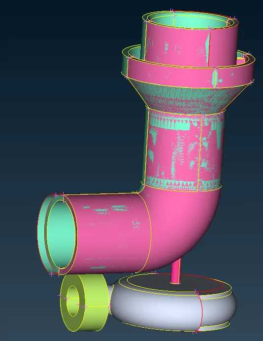
Step 2: Perform Geomteric checks using Checks --> Check manager --> Geometry_Checks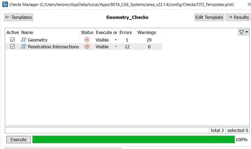
Step 3: Remove the overlapping surface using PID Property manager by deselecting the Overlapping color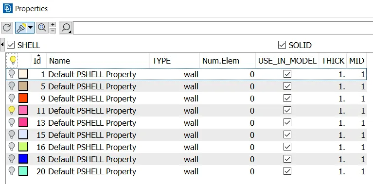
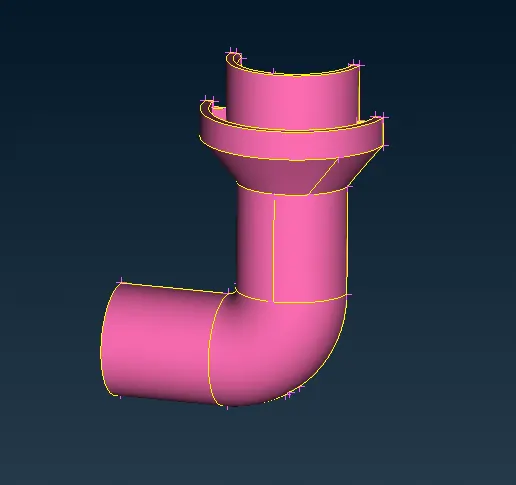
Step 4: Now delete the respective PID from the property manager window
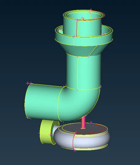
Step 5 : Now create a new faces / delete the unwanted faces from the turbocharger model inorder to remove the single cons.
Inorder to create a new face,Go to Face --> New --> Coons option selecting the respective entities / to delete a face, go to Face --> Delete by selecting the entities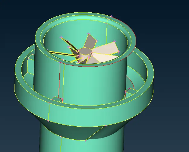
Inorder to solve the above single cons, select Curve --> Transform by selecting the curve from the above single entity to form a curve.
Select the entity , middle click and then select the hot points based on the direction of arrow shown. After this, curve will be created, which will act as a guide to create the new face
Once created the face, delete the curve from Curve --> Delete option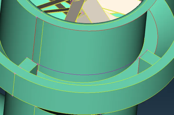
Before Deleting curve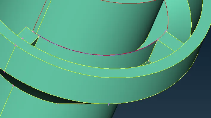
After deleting curve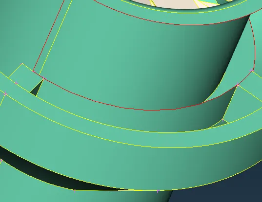
Step 6: Follow the above steps to clear the geometry errors.
For the below single cons, create a middle hotpoint and then select global transform option --> Copy --> Select the entity face required to mirror
Then select the middle mouse button and click symmetry --> Mirror 3 point plane (select the three hotpoints) to create a symmtry entity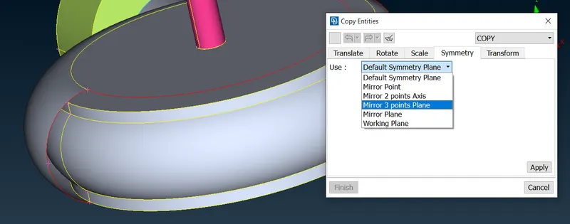
Step 7: Do geometry check again to indentify the Errors to cleanup
After this need to remove the intersection between the parts in model.
Usually, remove the intersection using global delete option 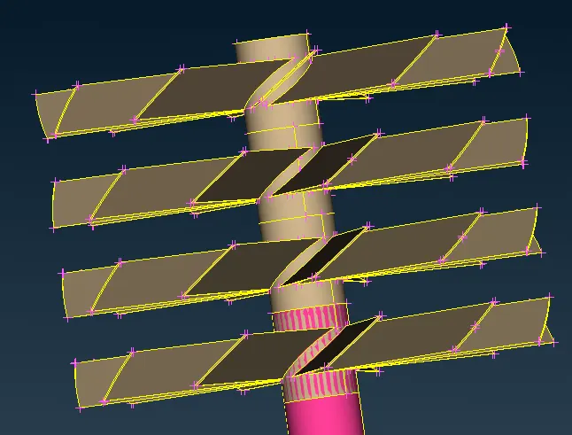
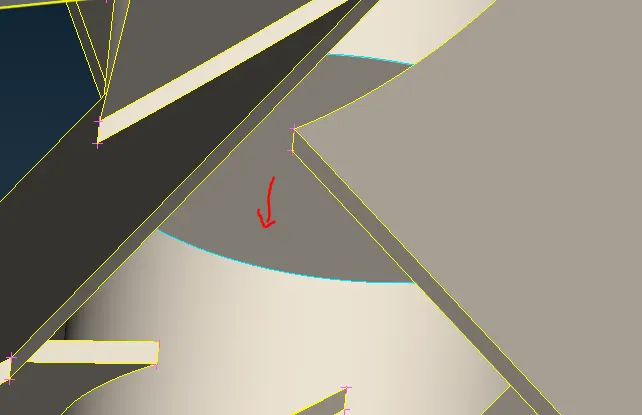
In the above image, shows that the particular face have triple cons which means three faces intersecting each other. But naturally it should not have three faces, and also inorder to have the FVM process in CFD, only single volume is acceptable. So need to delete the highlighted face (red arrow) completely 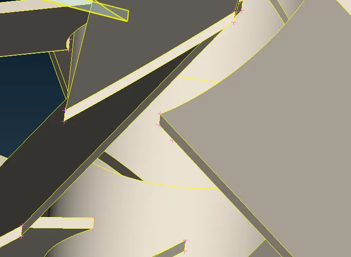
Follow the above steps until it completely resolves the geometric errors
Step 7 : After this, update the PID's name properly and assign it to the respective child parts in model. After this, do the surface mesh using CFD Mesh generation option by providing spacing option
Need to provide the min and max target length based on the inputs for the respective part
While doing this, use freeze option to freeze the surface mesh for same mesh type and length(inorder to avoid the mesh flow error since due to the different mesh length)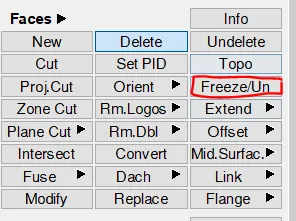
Step 8 : After doing surface mesh, need to go to the volumetric mesh deck and click define option to find out if ther volume is properly closed or not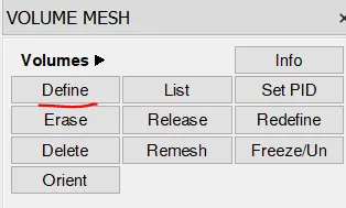
Then delete the exterior surface from the volume and then click Unstructure mesh option to assign the Tetra CFD / Tetra Rapid volumetric mesh and then right click select remesh option to mesh the surface into volumetric mesh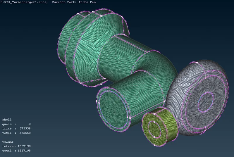
After this select cut plane, and click New --> Default XY and select somewhere in the model and then a new window pops up. In that select, New --> Part and then double click the part image to make a cut plane in the part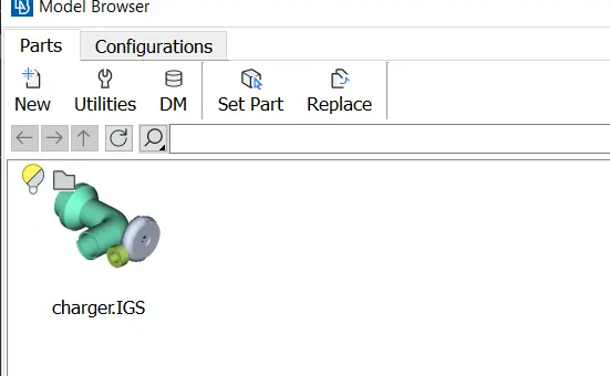
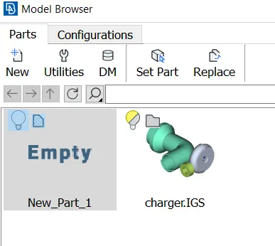
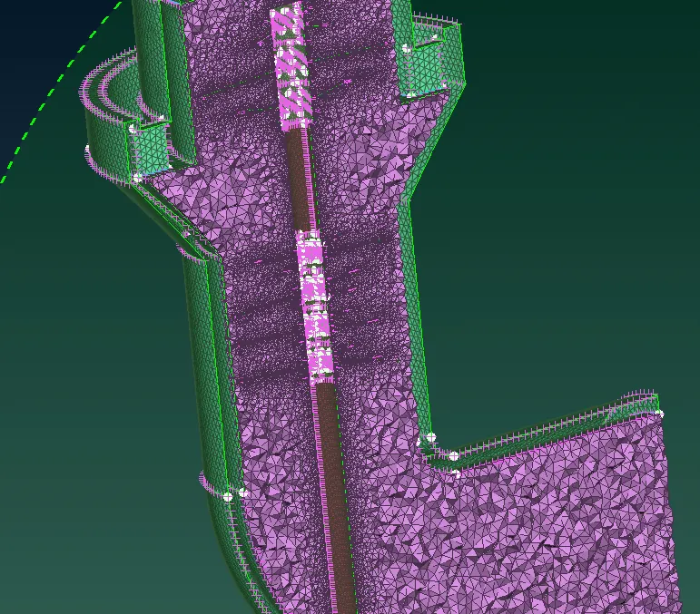
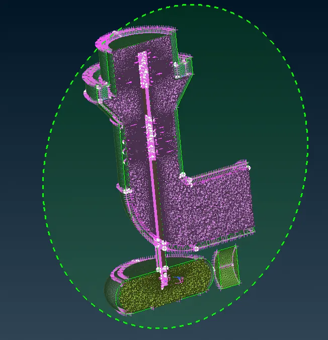
Now the final volumetric mesh based on the cutting plane XY is shown below