Week 3 Challenge : CFD meshing on Turbocharger
AIM:
- Make a volumetric mesh in the turbocharger's given geometry by first cleaning the geometry and removing any flaws, then making a surface mesh so we can proceed with the volumetric mesh, and finally selecting the required volumes and creating a volumetric mesh in those volumes.
OBJECTIVE:
- For the given model, check for the geometrical errors and perform Topology cleanup accordingly. Set three different target lengths as three different cases and mesh the model.
- Blade stage-1 = 1 mm
- Blade stage-2 = 1 mm
- Impeller = 2 mm
- Shaft rotor = 1 mm
- Turbo casing = 5 mm
- Compressor casing = 5 mm
- Inlet casing cover = 5 mm.
INTRODUCTION:
- ANSA is a computer-aided engineering tool for Finite Element Analysis and CFD analysis widely used in the automotive industry. It is developed by BETA CAE Systems. ANSA maintains the association between CAD geometry and the FE mesh.
PROCEDURE:
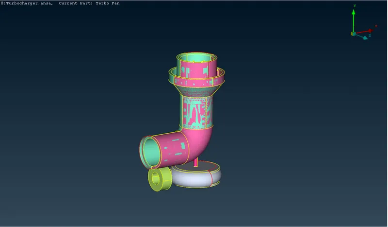
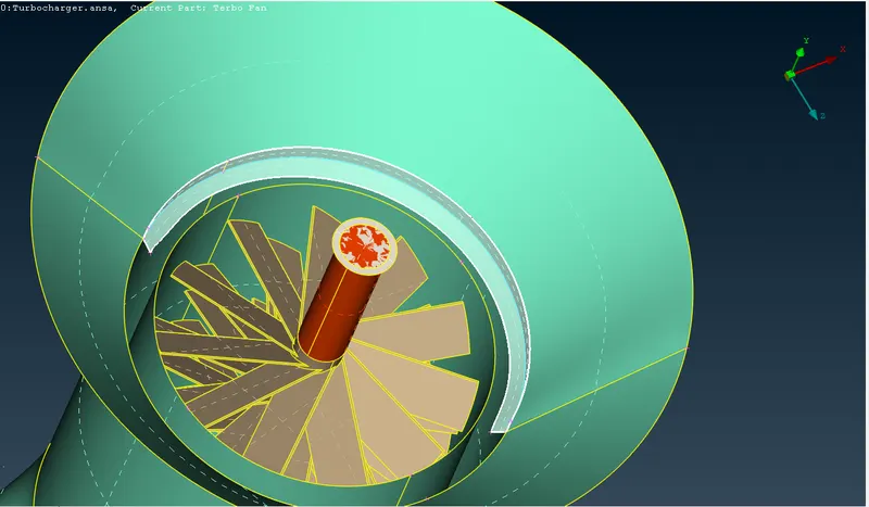
- OPEN THE MODEL: Open the model in ANSA as you see in the below image.
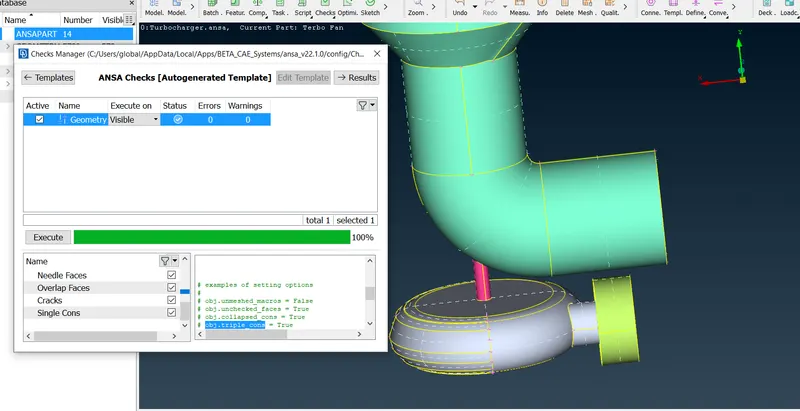
- As we can see the geometry has many flaws so we need to correct all on them. The major ones we are looking for are as follows
- Overlap faces
- Single cons
- Triple cons
- Duplicate surfaces or missing surfaces.
Given Geometry,
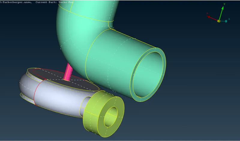
- These are the single cons we need to fix so let’s fix them one by one. The front red con we need to delete one face and create a new one as shown below,
- Make a volumetric mesh in the turbocharger's given geometry by first cleaning the geometry and removing any flaws, then making a surface mesh so we can proceed with the volumetric mesh, and finally selecting the required volumes and creating a volumetric mesh in those volumes.
- Now we can select the pink PDI easily and delete it like this we need to use the appropriate option to remove the flaws from geometry correctly.
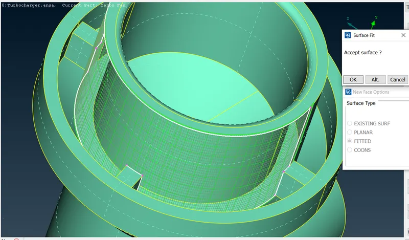
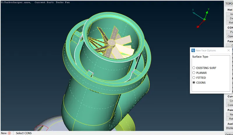
- For the second problem, the face we need to make must be in some separate parts as shown. For that, we need to use a multi-project for projecting the hot points and creating surfaces one by one.
- By checking the geometry we can spot the errors and can clear it.
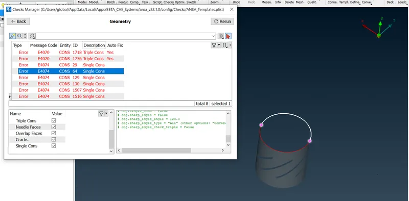
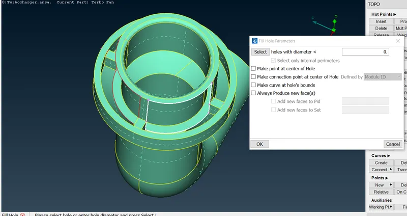
-
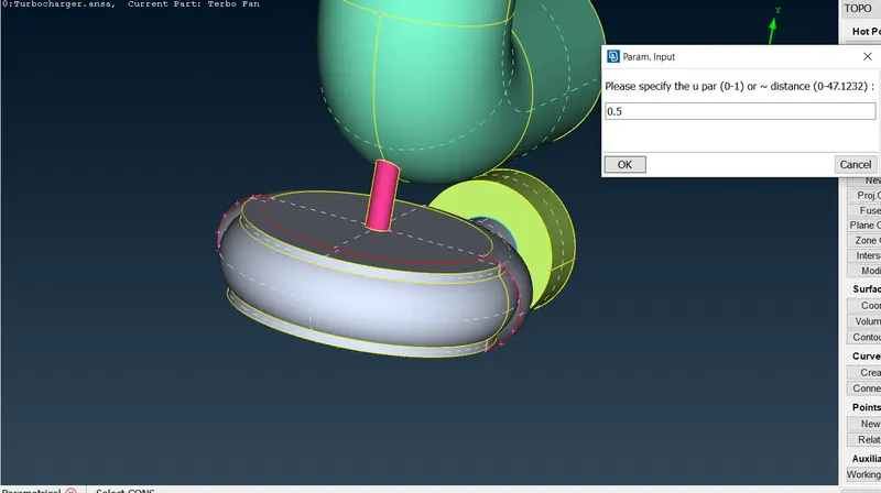
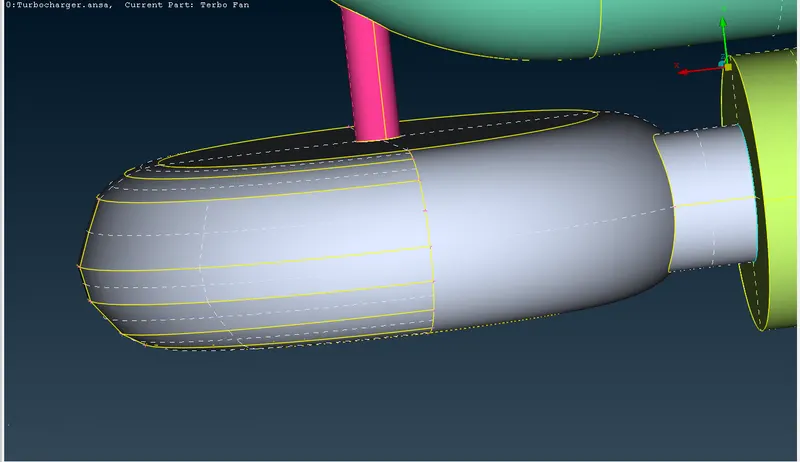
Like this, we need to face one by one and complete the entire hole. At the bottom, we cannot make the phases entire at one time as the ANSA doesn’t predict the correct faces so we need to divide this one as well,
-
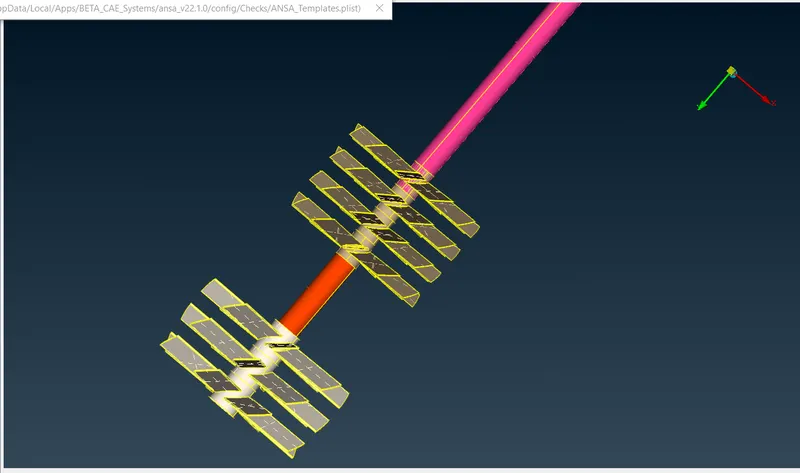
The intersection option will itself show the option to delete the exceeding surface, Also, there are further clean-ups to make the geometry ready for meshing for many overlapped surfaces and unwanted surfaces, like in the shaft of the rotor we need to make the entire shaft in a single volume it will help us in volumetric mesh so we need to delete all the surfaces in the between.
- Now we need to check overlap surfaces under all the surfaces we may find some in the rotor shaft and we need to cut the shaft in some places by using the project cons option and delete option.
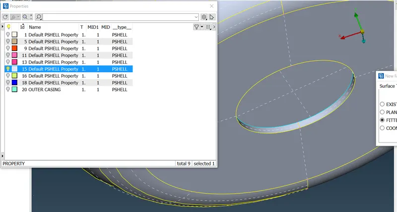
- Now we can name the PIDs as required,
MESHING:
- Now, our surface mesh sizes are as follows,
- Blade stage 1 = 1mm
- Blade stage 2 = 1mm
- Impeller = 2mm
- Shaft rotor = 1mm
- Turbo casing = 5mm
- Compressor casing = 5mm
- Inlet casing cover = 5mm
- Now in ANSA we usual put the target length in 3 locations Mesh parameter, Quality criteria and length in which we select macros and parameter
- In this geometry there will be many macros where the edge will be shared by two types of target length in such cases, we need to keep the target length in macros and parameters in length option fluting between the two separate target lengths.
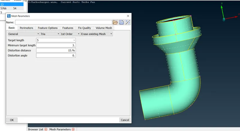
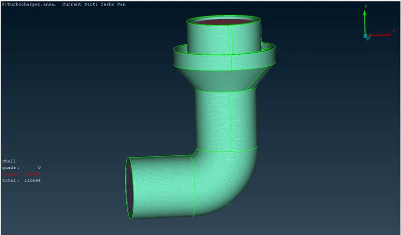
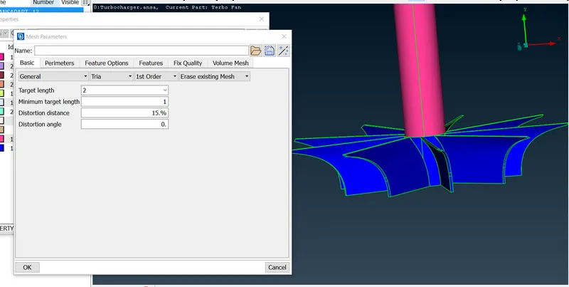
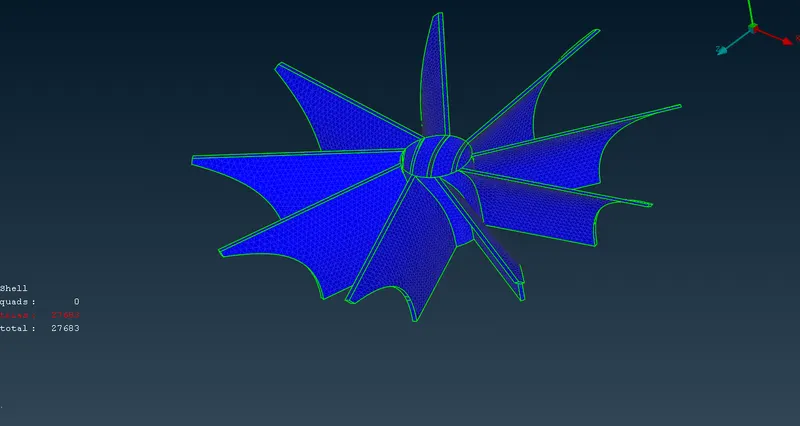
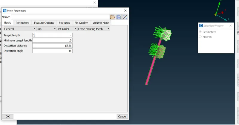
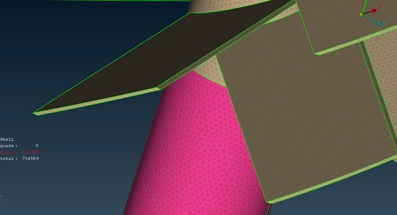
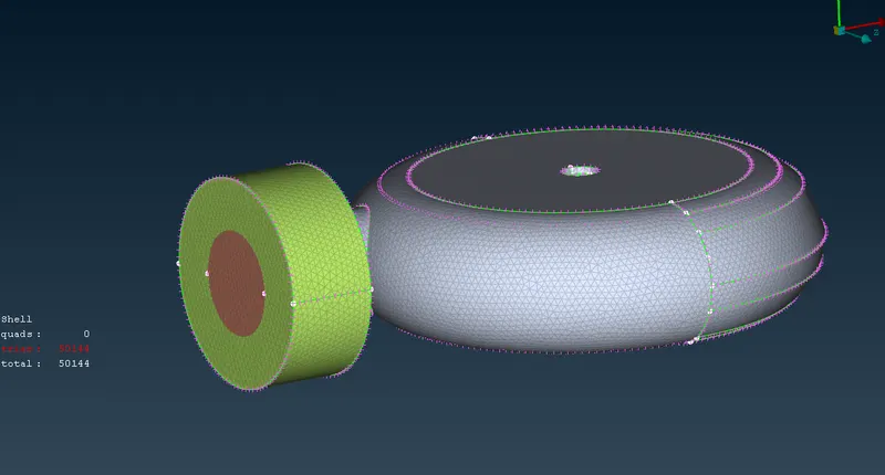
- Once the geometry errors are cleared we can move to volumetric meshing.
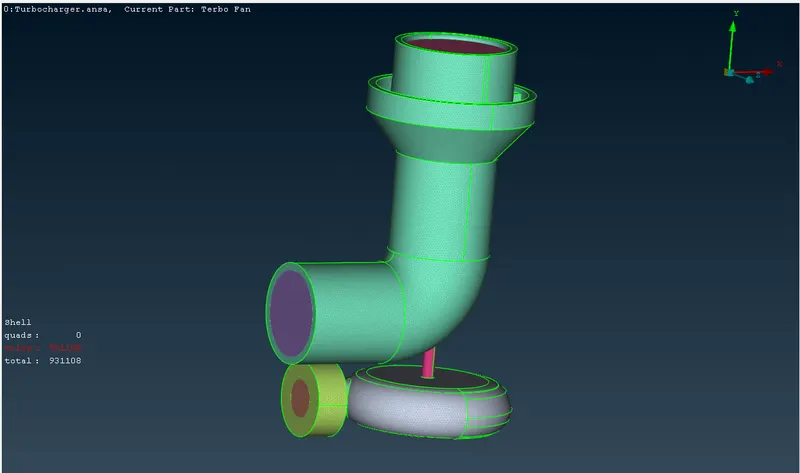
- Final geometry mesh.
-
As shown in fig the mesh of the outer casing must range from 1-5 so it can accommodate the same. After meshing all the components as per the target length, we must check that there are no unmeshed surfaces if there are any, we cannot do volumetric mesh.
VOLUMETRIC MESHING:
- Volumetric meshing can only be done after 2D meshing, now to check which volumes are capable of getting a mesh we can use DEFINE from volume and the whole-body option then Ansa will show all the volumes present in the body.
- We need to check which volume is actually the volume in which fluid is going to be present and which other is only a thickness of our solid body.
- PDI which represents the volume of area in which fluid is going to be present can mesh that area.
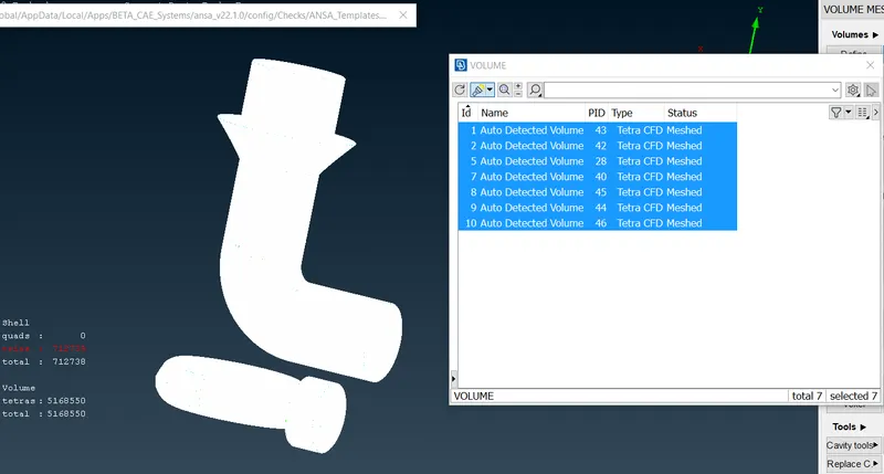
- After checking everything our volume which is to mesh will look like this,
-
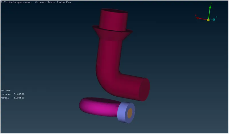
Now, to do volumetric mesh it is easy we just need to select the PID from the list and do right click and select Re- Mesh after that it will ask for type as we need the mesh for CFD purposes we can choose tetra CFD and click ok then the volume will start meshing and as the element size increases the software starts to work slowly. For bigger volumes, it may take some time.
LEARNING OUTCOMES:
- The glitched surfaces are eliminated in Topo.
- Different techniques of face-topo command.
- The meshing of various sub-parts is a good learning process.
- Volume meshing is a good learning outcome.
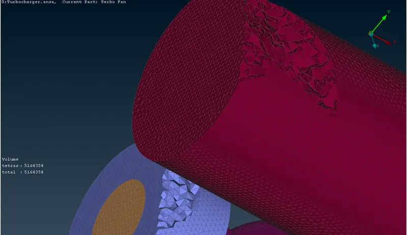
CROSS SECTION AFTER MESHING:
CONCLUSION:
- The meshing for both surface & volume is been done and the model is been attached to G-drive. While modelling many error rectification is been done and this will help a lot in further challenges.
UPLOADED MODEL:
https://drive.google.com/file/d/1E6S_G-p6nre7Kf3NHW9Ca5qXnru1a8nh/view?usp=sharing
- As the size of the model is too large to upload directly, the 'google drive' link is been shared to access the corrected model.