Week 3 Challenge : CFD meshing on Turbocharger
Aim:
- The aim is to refine the geometry and perform surface and volume mesh.
Take Away:
By the end of this article you will be familier with,
- Exploring different option to refine the geometry (fill hole, new faces, creating hot points etc).
- Meshing each component individually for refined and mesh where ever necessary.
INITIAL GEOMETRY:
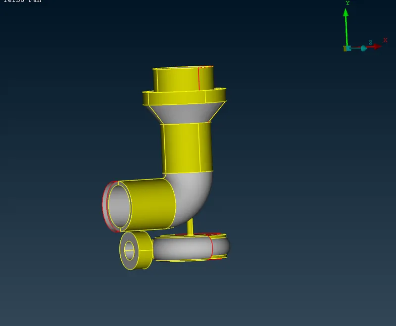
Errors in the Geometry:
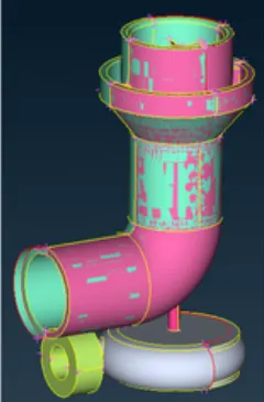
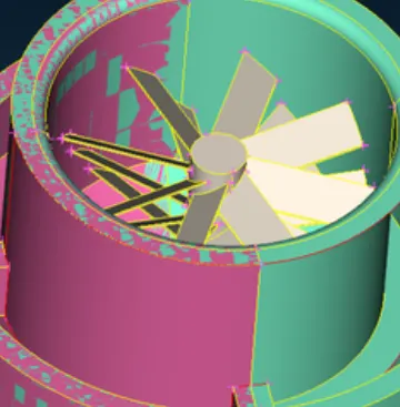
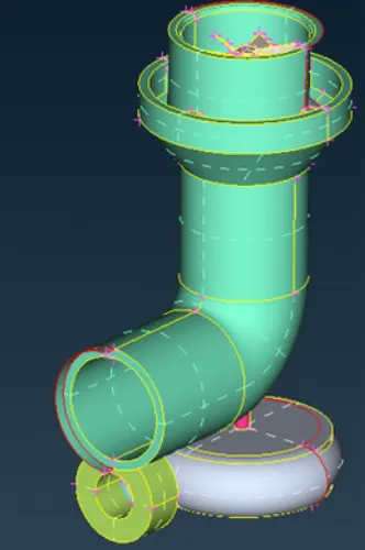
- The above figure shows what kind of topology clean up is required.
- Whole geometry is filled with these kind of errors and we will be discussing the rectification of these errors.
TOPOLOGY CLEAN UP:
- The very first step is to do a GEOMETRY CHECK.
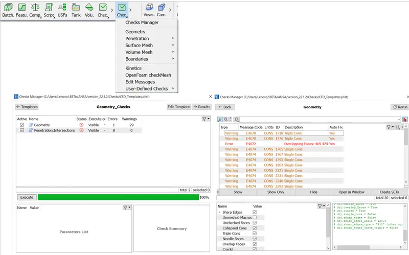
- Clicking on each of the errors, one can see in the GUI where is the error actually located.
- It is better to clean the geometry part by part.
- Once the geometry is ready for meshing, we will be setting PIDs for better model control while meshing.
Essential Tools:
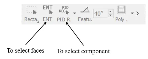
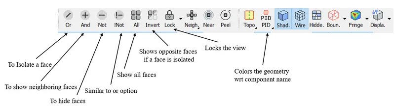
----> Exploring removal of Overlapping faces:
- Hide the green surface.
- Make sure you are in PID mode.
- After hiding the green face, you will be left with pink faces which is not necessary.
- Delete the face.
with overlapping surfaces :
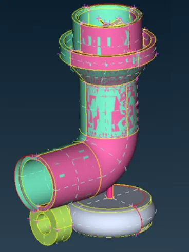
Unwanted :
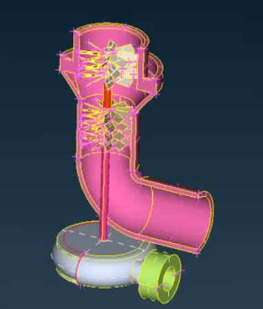
without overlaping :
----> Exploring the FILL HOLE option:
- Here, first the entire edge is removed.
- Then the void is filled with the help of FILL HOLE option.
- Delete the face.
- Select FILL HOLE option, select bounding cons to fill the gap. (TOPO --> FACES --> FILL HOLE).
----> Exploring the INSERT HOT POINTS and then create faces:
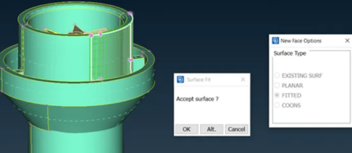
- In this particulaer scenario, FILL HOLE will not work.
- As seen this does not work.
- So, the alternative is to create HOT POINTS using existing HOT points.
- After selecting the points, project onto the upper cons.
- Select PROJECT option. (TOPO --> HOT POINTS --> MULTI PROJECT)
----> Exploring the INTERSECT option:
- This option is used to make intersection between two surfaces and form a triple con for furthur removal of the face.
- Select INTERSECT option. (TOPO --> FACES --> INTERSECT).
- It asks you for two sets of faces, select the faces that intersect.
- Then delete the unwanted region.
----> Exploring the PARAMETRICAL option:
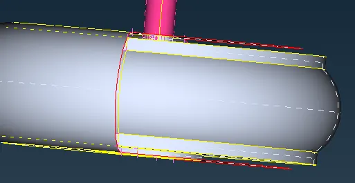
- This is used to create hot points on a existing cons.
- Select PARAMETRICAL option. (TOPO --> HOT POINTS --> PARAMETRICAL)
- It asks you to specify the distance as it assumes the distance is 1 mm. (kind of percentage of actual distance)
- This tool will be used to cover the following region:
- Final output
----> Exploring the CONS PROJECT option:
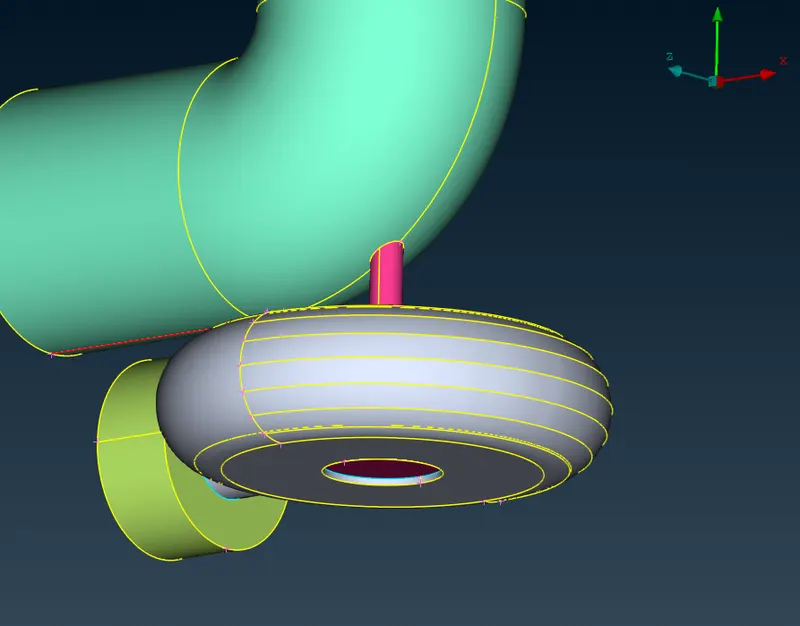
- This tool is used to project the cons on to other face to seperate the faces.
- Select PROJECT option. (TOPO --> CONS --> PROJECT)
- It asks you to select set of edges/cons to be projected and later asks you to select the face on which the edges/cons are supposed to be projected on.
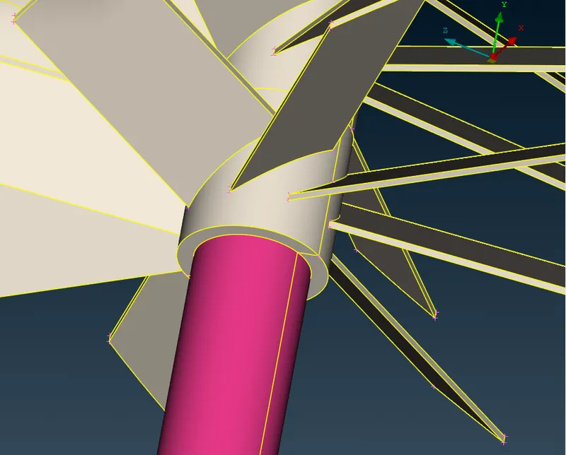
- Then we have to close all the inlets and the outlets for the volumetric mesh as shown.
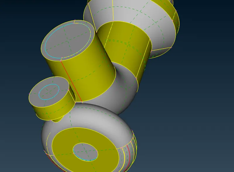
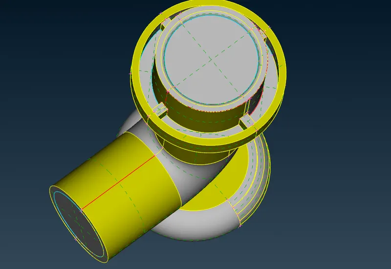
SETTING UP THE PIDs :
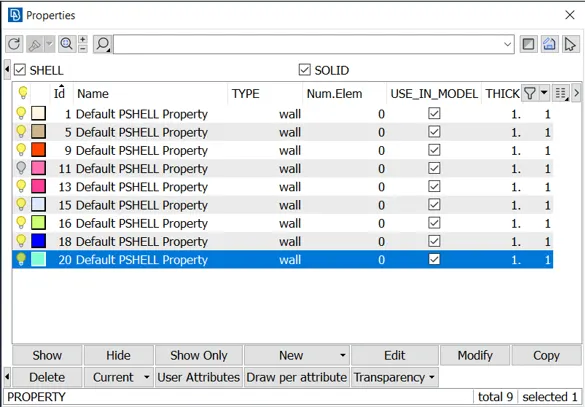
- Select the PID option present in ribbon.
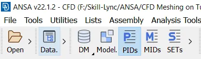
- A window will pop up with pre assigned names.
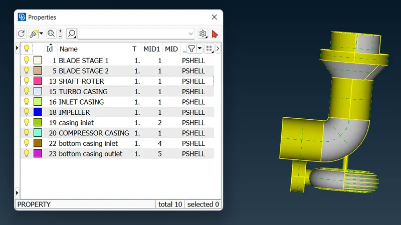
- One must assign proper names for better identification.
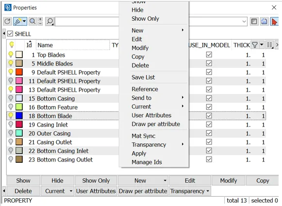
- Right click on the pre defined PIDs and select APPLY option.
- Next step is to select the face/component.
- Finally mention the names as we want.
MESHING UP THE GEOMETRY :
- There are regions where mesh has to be finner for better capturing of physics and there are regions where physics is not much of an importance.
- So, each of the component/PIDs are meshed individually for variable mesh element size.
- To mesh the component individually, only the PIDs of interest should be visible, rest must be hidden.
- This way we can work our way out to mesh the individual components.
- Below is the chart of different element size for different PIDs:
- Blade stage-1 = 1 mm
- Blade stage-2 = 1 mm
- Impeller = 2 mm
- Shaft rotor = 1 mm
- Turbo casing = 5 mm
- Compressor casing = 5 mm
- Inlet casing cover = 5 mm
- Starting with the make sure you are in Mesh deck.
- Use the tria meshing for all the components.
Meshing process is same for all the components, but we have to change the Target length, Min length and Max length according to the components.
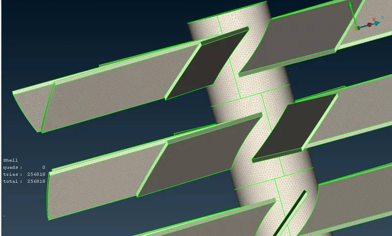
1) Meshing up the Blade stage 1 :
- Target Length = 1 mm
- Minimum Length = 0.5 mm
- Maximum Length = 2 mm
- The above values must be specified in MESH PARAMETERS AND QUALITY CRITERIA.
2) Meshing up the Blade stage 2 :
- Target Length = 1 mm
- Minimum Length = 0.5 mm
- Maximum Length = 2 mm
- The above values must be specified in MESH PARAMETERS AND QUALITY CRITERIA.
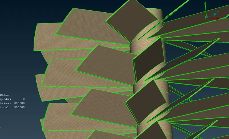
3) Meshing up the Impeller:
- Target Length = 2 mm
- Minimum Length = 1 mm
- Maximum Length = 3 mm
- The above values must be specified in MESH PARAMETERS AND QUALITY CRITERIA.
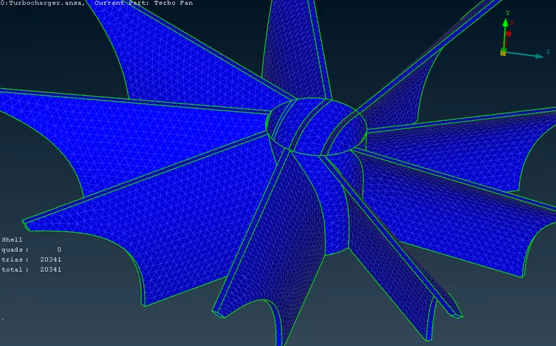
4) Meshing up the Shaft roter :
- Target Length = 1 mm
- Minimum Length = 0.5 mm
- Maximum Length = 2 mm
- The above values must be specified in MESH PARAMETERS AND QUALITY CRITERIA.
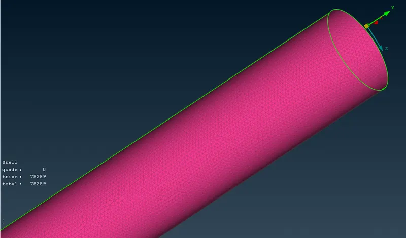
5) Meshing up the Turbo Casing :
- Target Length = 5 mm
- Minimum Length = 3 mm
- Maximum Length = 7 mm
- The above values must be specified in MESH PARAMETERS AND QUALITY CRITERIA.
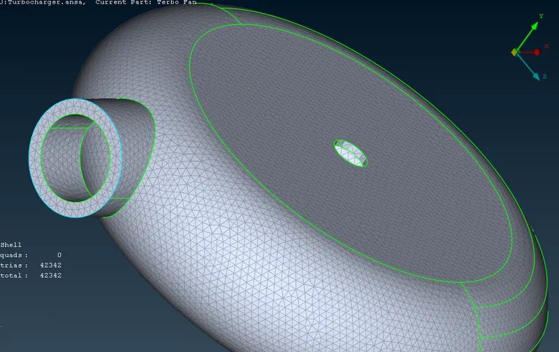
6) Meshing up the Compressor Casing :
- Target Length = 5 mm
- Minimum Length = 3 mm
- Maximum Length = 7 mm
- The above values must be specified in MESH PARAMETERS AND QUALITY CRITERIA.
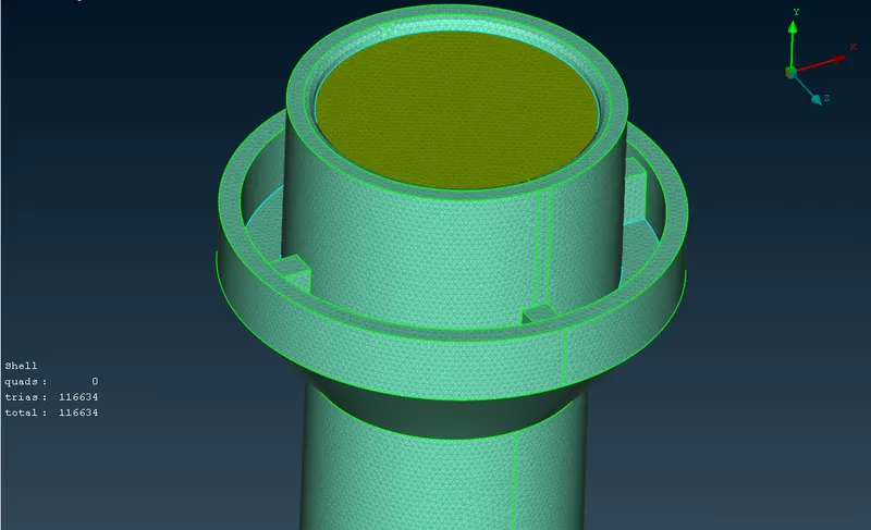
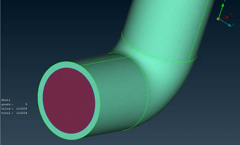
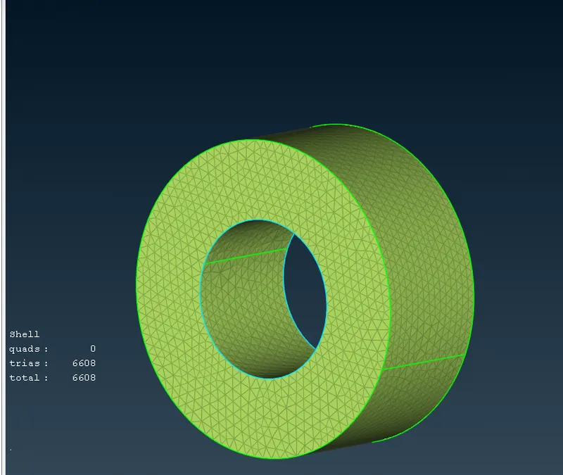
7) Meshing up the Inlet casing cover :
- Target Length = 5 mm
- Minimum Length = 3 mm
- Maximum Length = 7 mm
- The above values must be specified in MESH PARAMETERS AND QUALITY CRITERIA.
VOLUMETRIC MESHING :
- Now we can proceed with volume meshing.
- Select DEFINE option. (MESH --> VOLUME -->DEFINE).
- Pop up window will ask you for the whole database to mesh. Select ok.
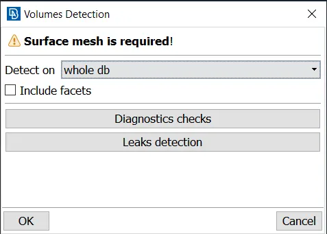
- ANSA will auto detect the voids in the geometry and try will try to fill it.
- Some of the volume generated is not required as the fluid is not going to flow through it.
- Therefore, we must delete those generated volumes.
- Assurity can be done by selecting the paramater and looking at the preview.
- After deleting the unwanted volume mesh, ANSA has still not mesh the required volume.
- Inorder to do that we have to remesh the entire left over domain.
- One has to choose tetra CFD option while meshing.
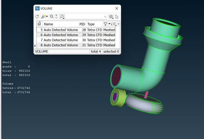
- Remesh the domains, by right clicking on undefined (see in fig) and select tetra CFD.
- After meshing the entire domain, the same window (above) should look like,
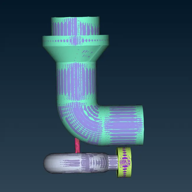
- Then finally go to the TOPO then we see the geometry like this.
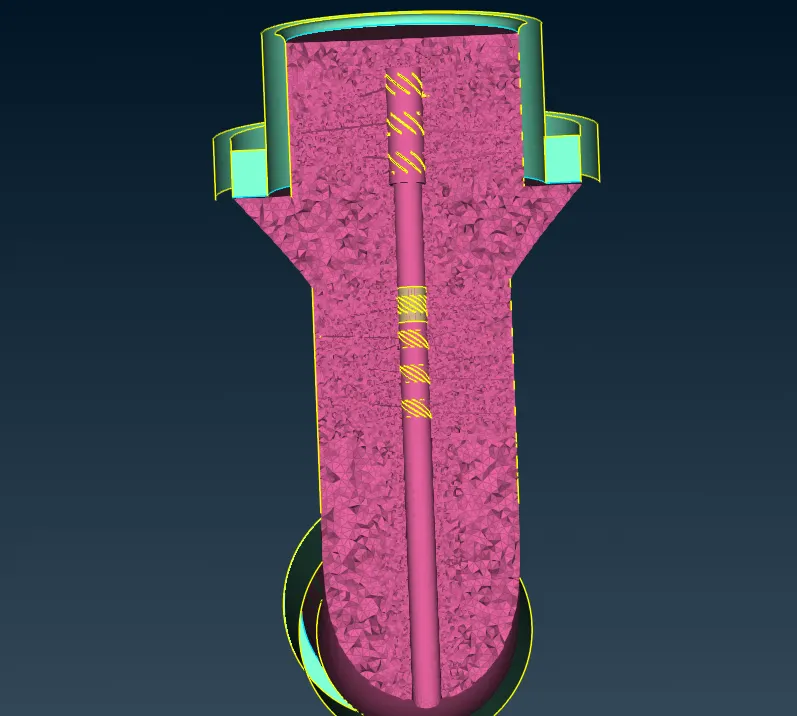
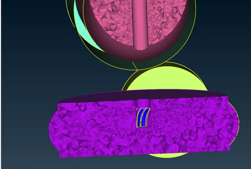
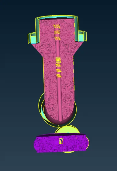
- And when we cut the geometry into the half we find the volume meshed part.
OUTPUT :
CONCLUSION :
- Achieved volumetric mesh of the turbocharger model.
- Different mesh length size tend to give errors at the contact regions of 2 different mesh length regions, therefore mesh ranges can be given to avoid erasing of mesh.
- Volumetric mesh can be achieved only after creating surface mesh successfully, or else the geometry can give fatal errors while volume meshing.
- Overlapped surface can be deleted using the universal delete option.
- Unecessary single and triple cons can be removed and editted using different tools such as cons project, topo, release and fine tools while goemetry clean up.
- Successfull volumetric mesh can be achieved only after correct geometric clean up and surface mesh.
GOOGLE DRIVE LINK :
zip file:
https://drive.google.com/file/d/1at9JAGVPL_kZx3Ibo4dZ3yFpkB5-_GNL/view?usp=sharing
Normal file:
https://drive.google.com/file/d/1e4QznjND13aRfvEjv-YAk75OS0ynMssf/view?usp=sharing