Week 3 Challenge : CFD meshing on Turbocharger
WEEK 3 CHALLENGE : CFD MESHING ON TURBOCHARGER (VINITH)
QUESTION:
For the given model, check for the geometrical errors to make appropriate volumes. Create and assign PIDs as shown in the video. Perform surface mesh with the given target lengths as per PIDs.
1.Blade stage-1 = 1 mm
2.Blade stage-2 = 1 mm
3.Impeller = 2 mm
4.Shaft rotor = 1 mm
5.Turbo casing = 5 mm
6.Compressor casing = 5 mm
7.Inlet casing cover = 5 mm
Perform Volumetric mesh for the required volumes as shown in the videos.
Write a detailed report on your surface meshing & Volume meshing process
OBJECTIVE:
To check for the geometrical errors to make appropriate volumes. Create and assign PIDs as shown in the video. Perform surface mesh with the given target lengths for the different portions of the given geometry as per PIDs.
Also Perform Volumetric mesh for the required volumes as shown in the videos.
Write a detailed report on your surface meshing & Volume meshing process
SOLUTION:
Open the ANSA software and Log on performance 3 mode
Open the new file using options FILE > NEW FILE
Enable the shadow mode & PID to better view of the provided geometry
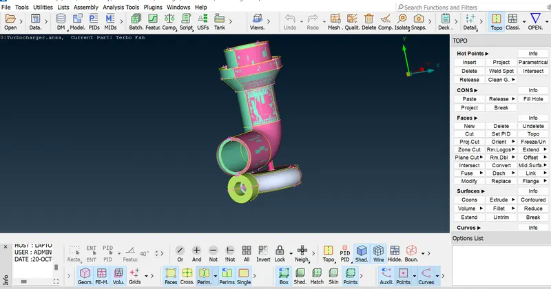
ENABLE LABELS, SHADOW MODE & PID
GEOMETRY CLEANUP:
Auto fix the existing geometry errors
TOPO > FACES>TOPO
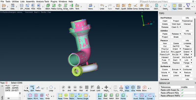
TOPO CLEANUP
Glitches and Multiple surfaces are clearly visibles in enables shadow mode, It confirms that existence of the overlapping surfaces and its to be removed.
Go to PID > Show only overlapped surface > Delete it by universal DELETE from the UTILITIES toolbar
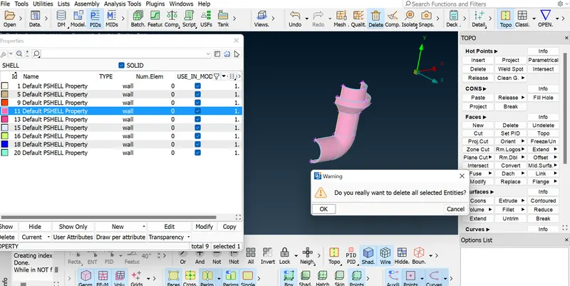
UNNECESSARY SURFACE-UNIVERSAL DELETE
Ensure the deleted part by clicking the PID TAB
Remove the unwanted shell property from PID list
Utilities Tool Bar > Compress option > OK
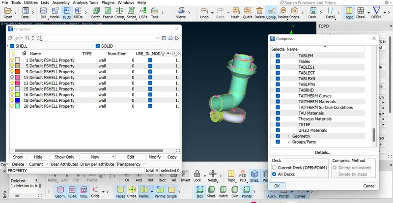
GEOMETRY LESS PID DELETE
Geometry checkup
identification of the location of geometry and intersection error to clear it one by one
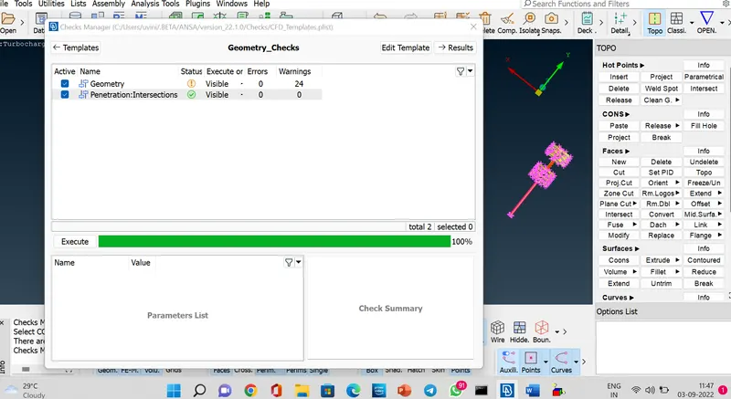
Tools>Checks>Checks Manager>Geometry checkup>Execute
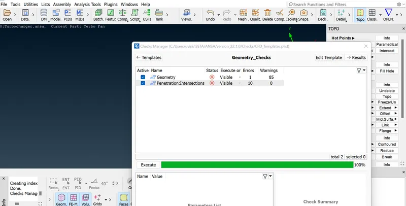
GEOMETRY & INTERSECTION ERROR CHECK
Removing of single cons presented in the geometry one by one. Clear the misaligned and overlap to make the geometry in a perfect shape.
Deleting of unwnated faces from the geometry
Topo>Faces>Delete>Selection of face id number>Delete
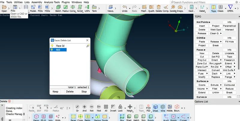
SURFACE DELETE
Now new face to be created based the existing coons
Topo>Faces>New>Surface type selection>Coons>Confirm the shape by preview>Create
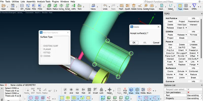
CREATING NEW SURFACES
Intersection Error removal from the compressor casing part
Topo>Faces>Intersect>Select first part>Select second part> KEEP (Necessary) or DELETE(Unnecessary)
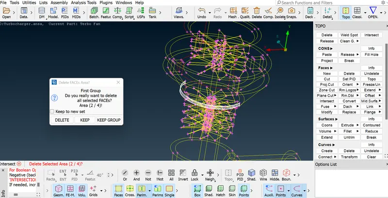
INTERSECTION OF COMPRESSOR CASING
Creating new faces to clear the uneven surfaces
Now create new faces by CUT delete the unwanted faces and surface TOPO > FACE>CUT
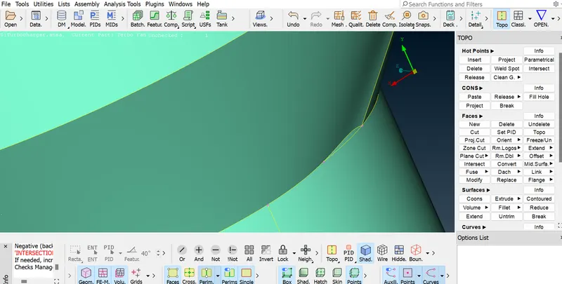
CREATE CUT
Now delete the unwanted faces and surface TOPO > FACE>DELETE
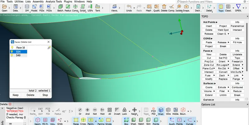
DELETE FACE
Creating the new surface TOPO > FACE > NEW > COONS > LOOP SELECTION
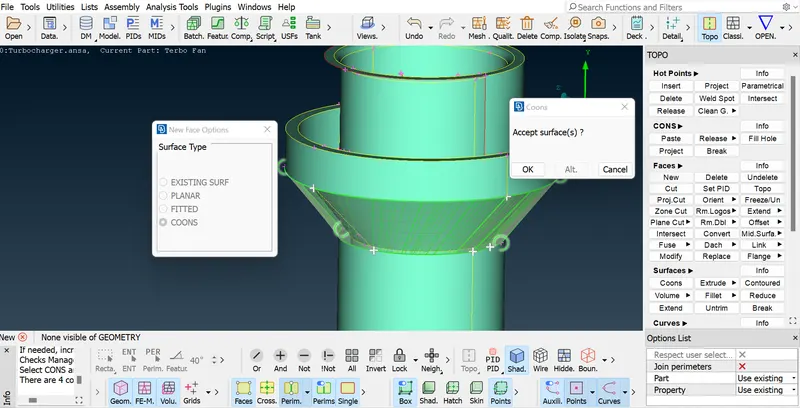
CREATE SURFACE
Delete the presented hot points – TOPO > HOTPOINTS > DELETE
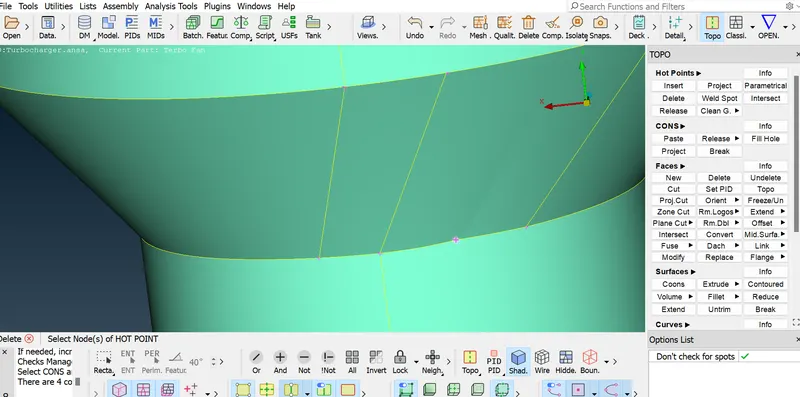
REMOVAL OF HOT POINTS
Create new curve face by using transform tool
TOPO > CURVES > TRANSFROM>SELECT COONS>2 POINTS ENITIY SELECTION
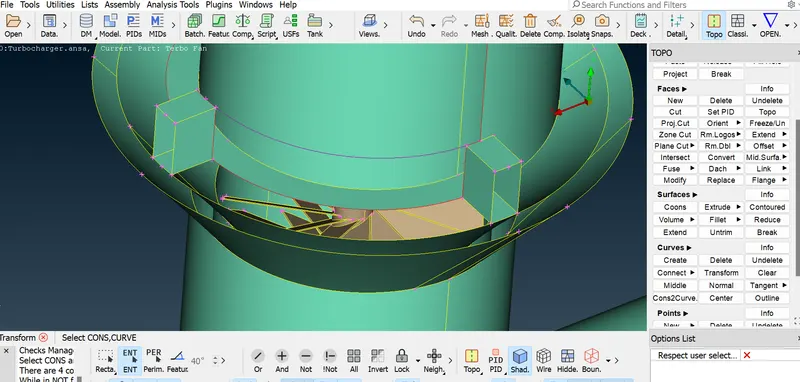
CURVE TRANSFORM
Creating the new face after madeup of new curve
TOPO > FACE > NEW> COONS>ENTITY SELECTION OF COONS to make the curve face
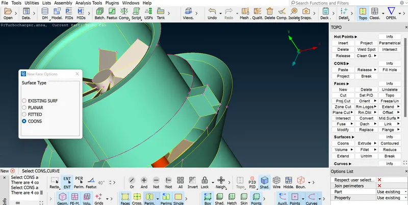
CURVE TRANSFORM
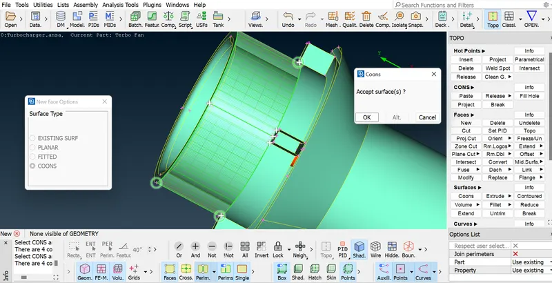
DELETE HOTPOINTS
Deleting unwanted curves
TOPO>CURVES> DELETE> selection unwanted curve part
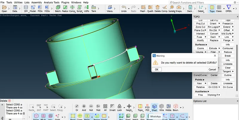
DELETE CURVES
Now copying the turbo casing impeller portion by transform method
Go to utility toolbar TRANSFORM > COPY > ENTITIES > Select portion to copy
Popup box will be go to Symmetry selection > Mirror 3 point plane
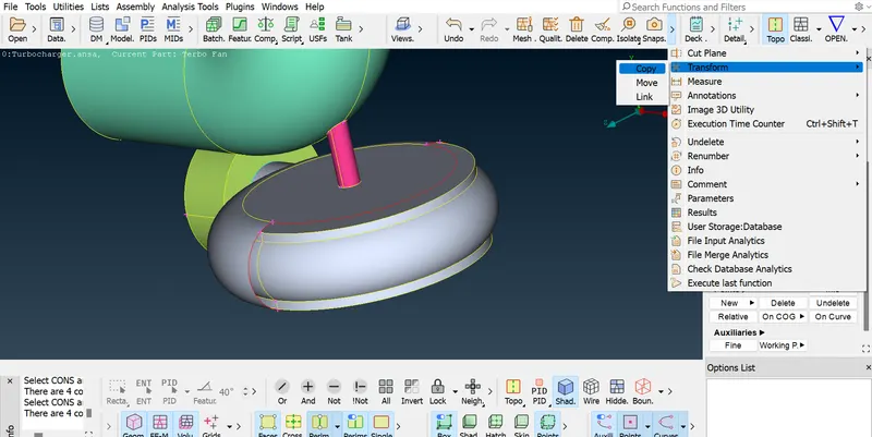
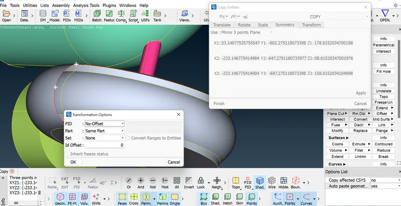
TRANSFROM SURFACE ( 3 POINT METHOD)
Close open portion by using fill hole
Go to, Topo>cons > Fill hole
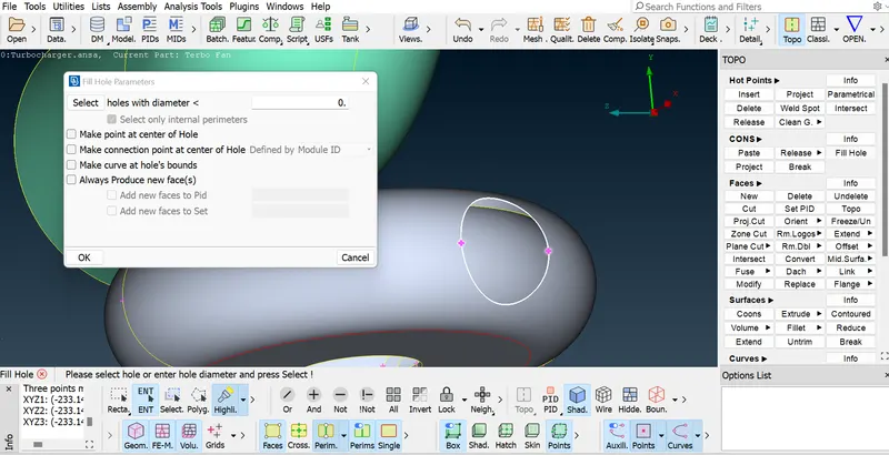
FILL HOLE
Topo cleanup to auto fixing the geometry errors
TOPO > FACES > TOPO CLEANUP
Next is To clear the Compressor casing blades and shaft intersection clear
First hide all the portions exclduing the shaft and Compressor casing blades
Go to PID Enable only shaft and Compressor casing blades , to be locked be starting the cleanup
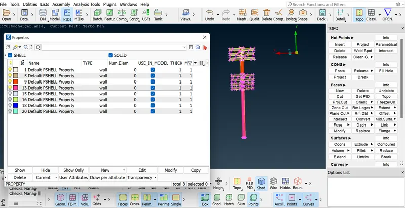
Delete the multiple sufaces presented in the one location
Topo>Faces>Delete>Selection of face id number>Delete
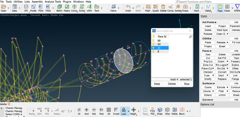
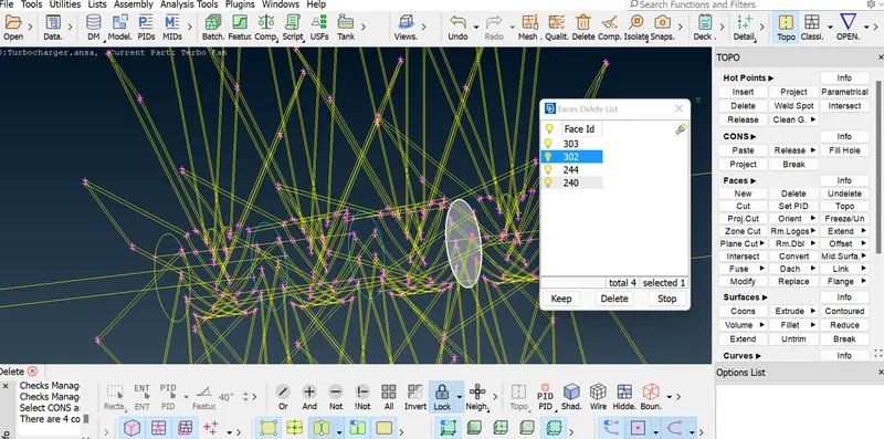
FACE DELETE
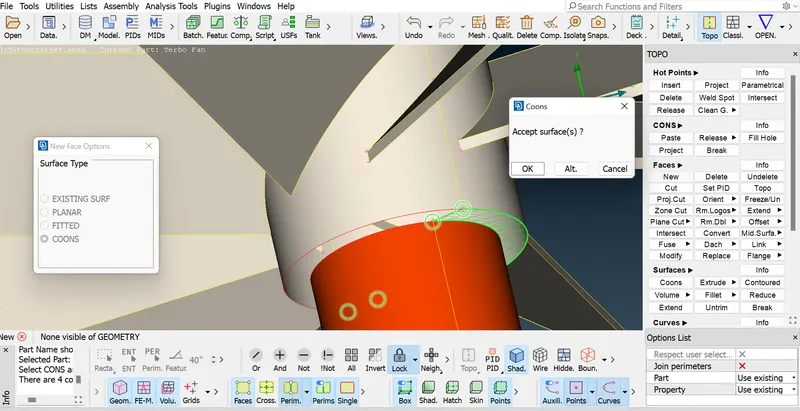
INTERSECTION OF SHAFT TO BLADES
Making the shaft and impeller blades shaft into one surface
Cons to be projected to create boundry as make it two surfaces
Topo>Cons>Project>select cons>selectface
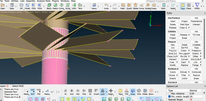
Now excess intersected surface to be deleted
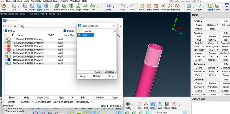
All the intersection errors presente in the shaft and blades portions were cleared
Next impeller casing and shaft intersection errors to be cleared by one by one
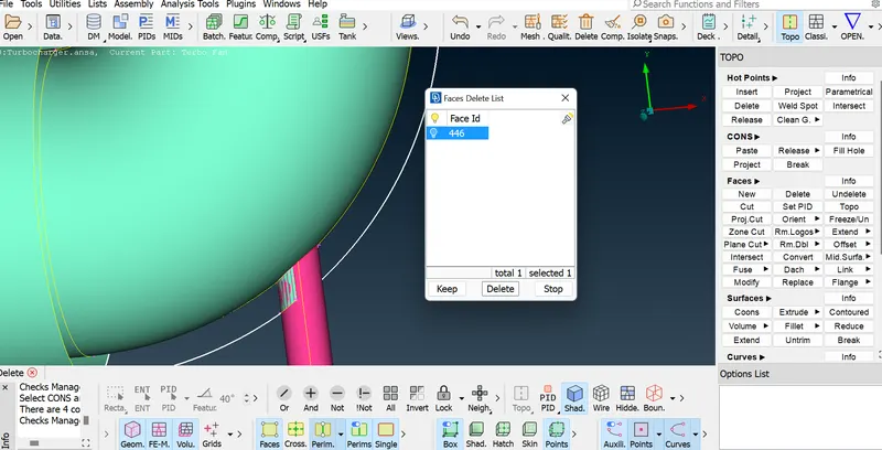
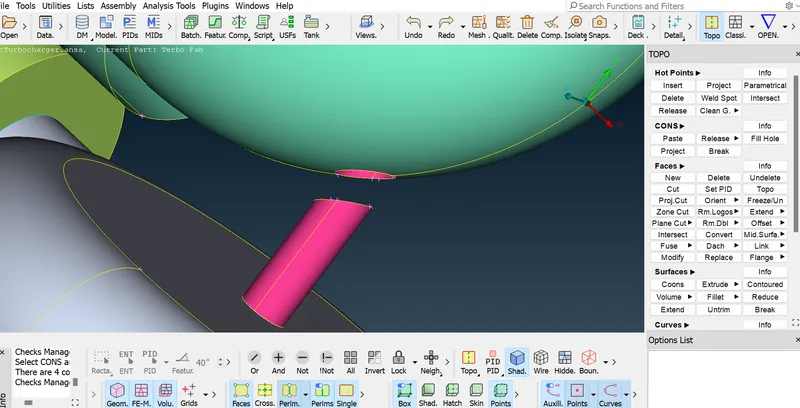
INTERSECTION & EXCESS SURFACE DELETE
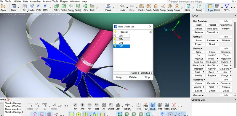
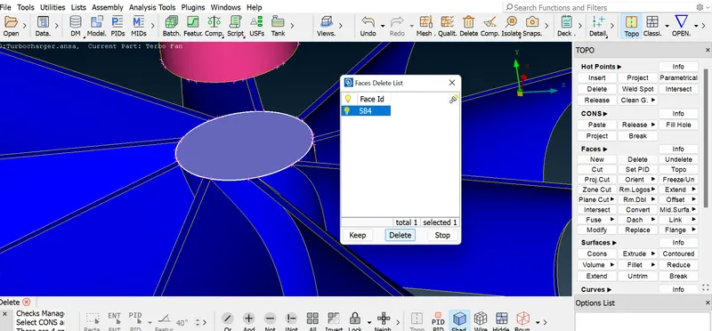
Delete the excess surface presente turbo casing inlet part
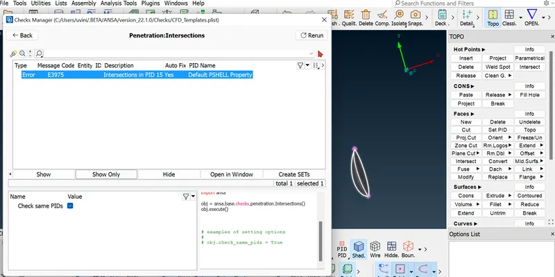
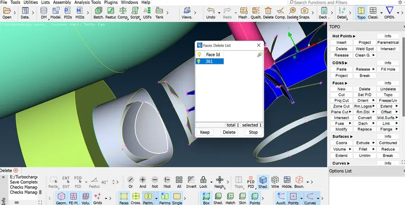
Now confirmty of intersection error fro check manager
INTERSECTION ERROR CHECKUP
Close all the openings aech parts to proceed for surface mesh
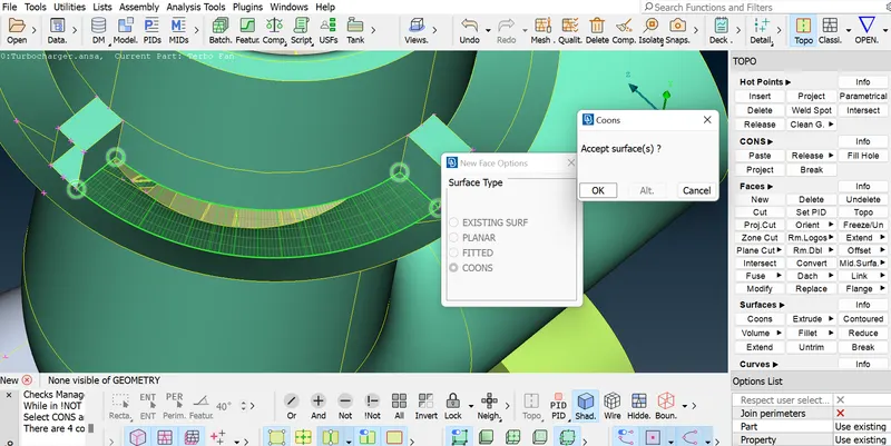
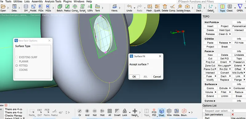
Required water type surface created to proceed surface meshing in below pic
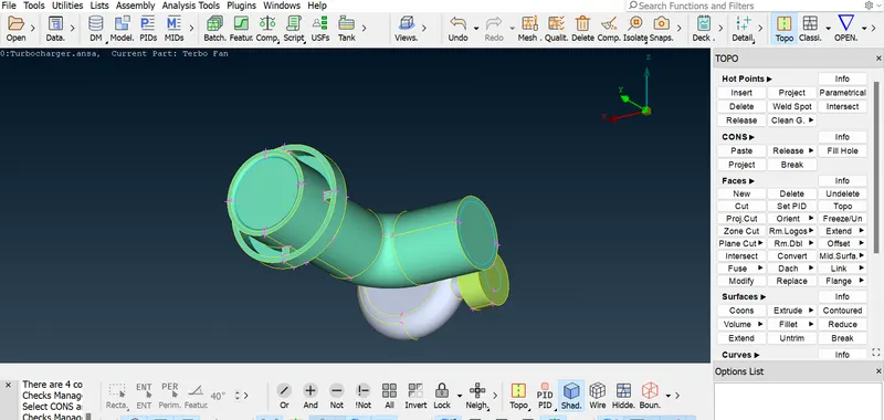
WATER TYPE GEOMETRY
Create and Asssign PID for individual parts as per provided part list
Each of parts are renamed as per provided name list and it is applied
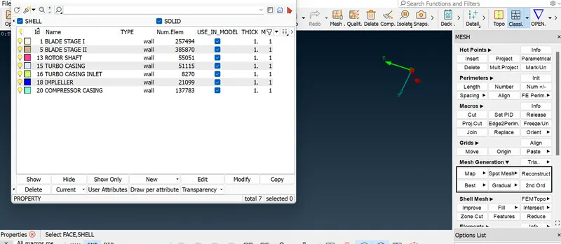
ASSIGNING OF PID
SURFACE MESH GENERATION
Mesh Generation setting (SPOT MESHING- Recommended)
- Blade stage-1 = 1 mm
- Blade stage-2 = 1 mm
- Shaft rotor = 1mm
Above mentione portions were separately selected by using PID since all the parts same mesh specification.
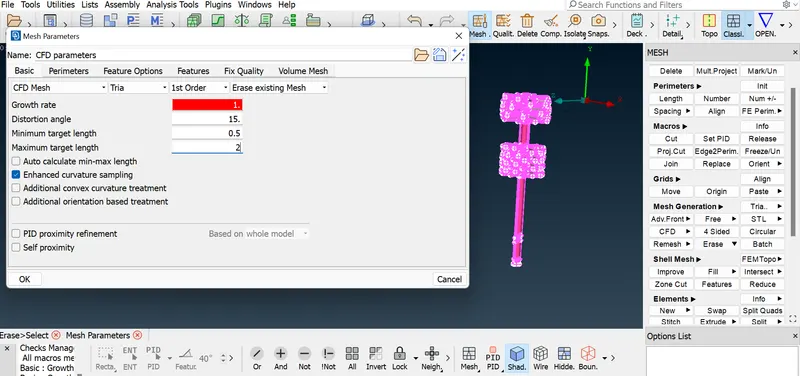
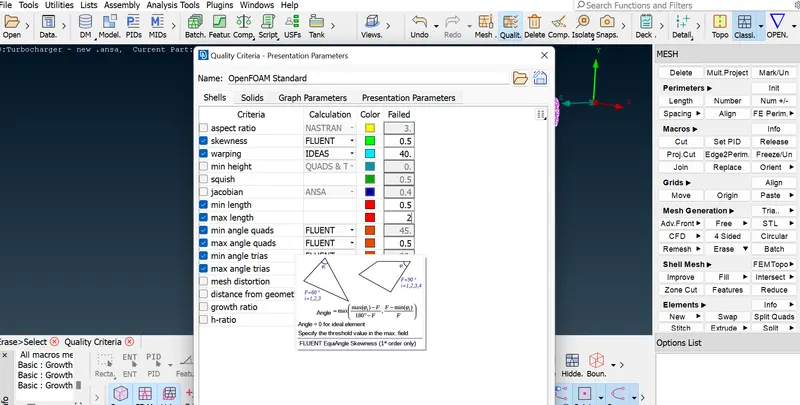
SURFACE MESHING SETTING
Specified size of mesh has beed generated for compressor casing blade and shaft portion
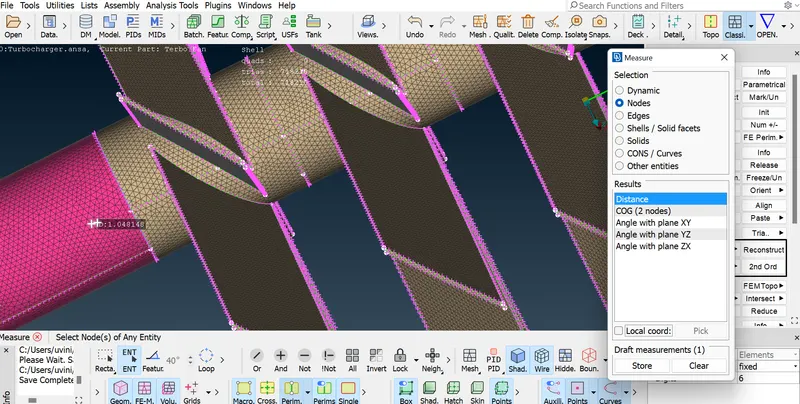
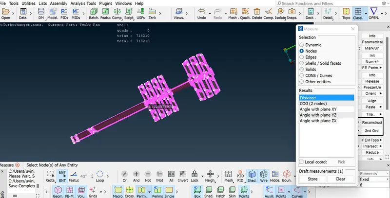
1 MM MESH GENERATION
Mesh generation for impeller
Impeller = 2 mm
Setting of mesh parameters Min target length - 1mm Max target lenghth - 3mm
Then setting of Perimeter and Macros to 2mm
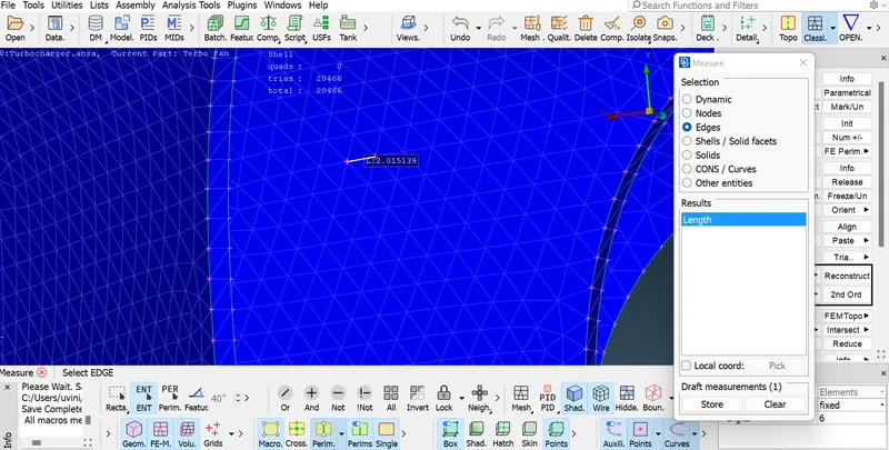
IMPELLER - 2MM MESH
Similarlly surface meshing to 5mm for below parts respectively
- Turbo casing = 5 mm
- Compressor casing = 5 mm
- Inlet casing cover = 5 mm
Setting of mesh parameters Min target length - 3mm, Max target lenghth - 7mm
Then setting of Perimeter and Macros to 2mm
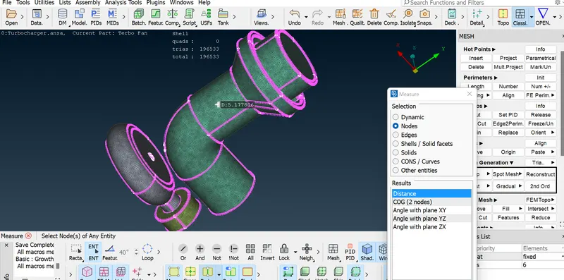
5MM MESH GENETRATION
Mesh regeneration to be done in whereever unmeshed part shown.
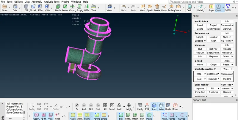
SURFACE MESHING VIEW
Surface mesh has been successfully completed.
VOLUMETRCI MESH GENERATION
Go to Modeules > Volume mesh > define
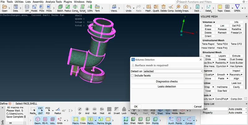
VOLUME MESHING STEPS
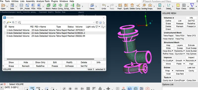
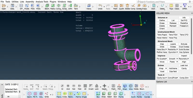
VOLUME MESHED MODEL
RESULT:
https://drive.google.com/file/d/1ItW3O-3zHagcnymr6SOpNvKXXmffal_-/view?usp=sharing
Thus the provided model check for the geometrical and intersection errors were cleared. PIDs created for the different parts of the model. Surface mesh has been generated with the given target lengths as per PIDs.
Also volumetric mesh also generated tetra rapid algorithm and Above attached Gdrive link is tha ansa file for your reference.