Week 3 Challenge : CFD meshing on Turbocharger
Detailed Report of Week 3 challenge:CFD Meshing on Turbocharger
AIM:
Correct the geometrical error of the given model, assign proper PIDs, do surface mesh and create volumetric mesh on the given model.
PROCEDURE:
* Download the given geometrical model of turbo charger.
*Open the turbocharger geometry in ANSA platform.
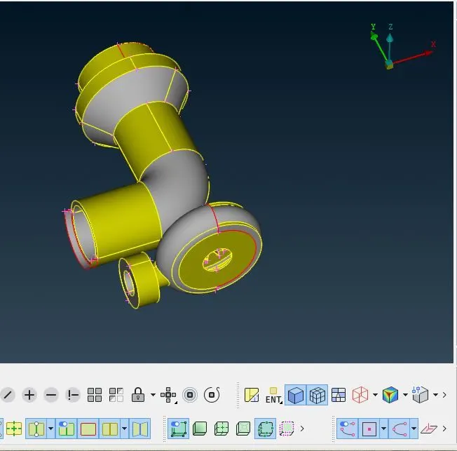
*Open the PID mode.
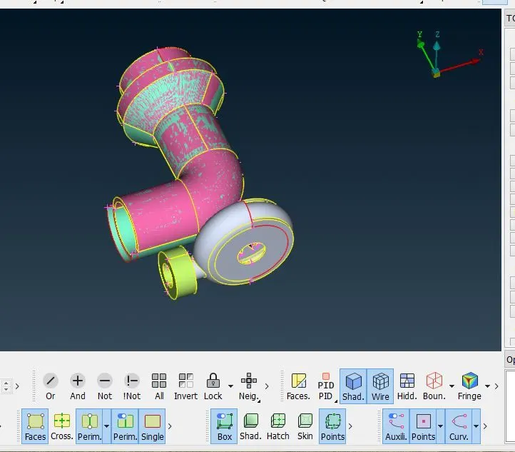
*Just do an overlook to the geometry.
*Just check the PIDs.
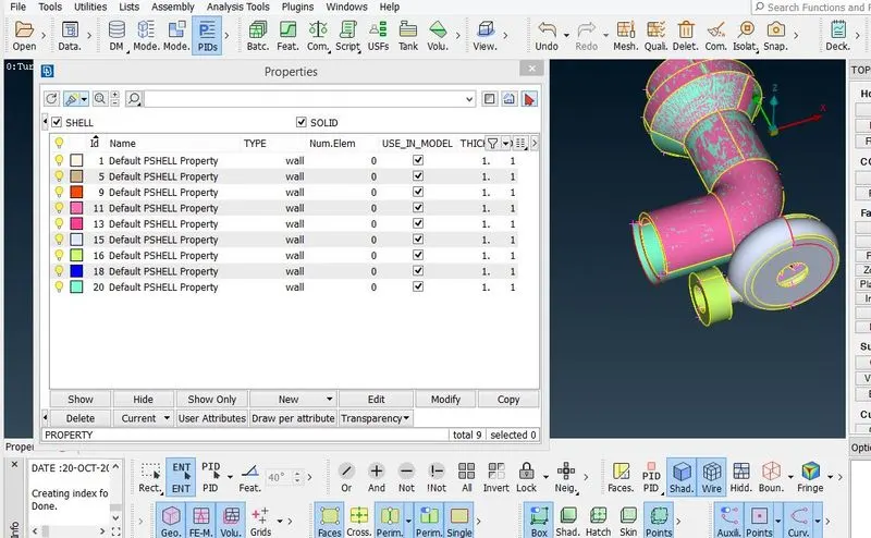
*Just do a TOPO for the entire geometry.
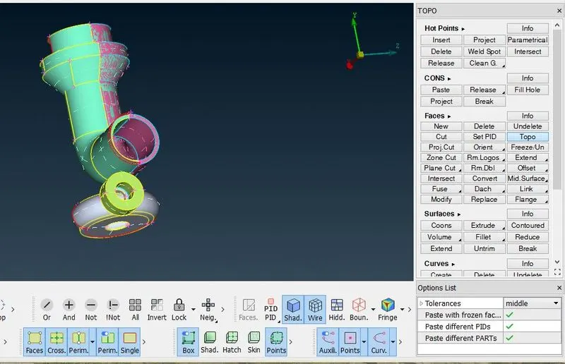
*Delete overlapped surfaces by selecting unwanted surfaces.
*By using PID option and Delete option delete unwanted surfaces.
*
*Delete extended surface by using Delete option.
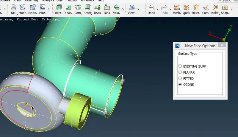
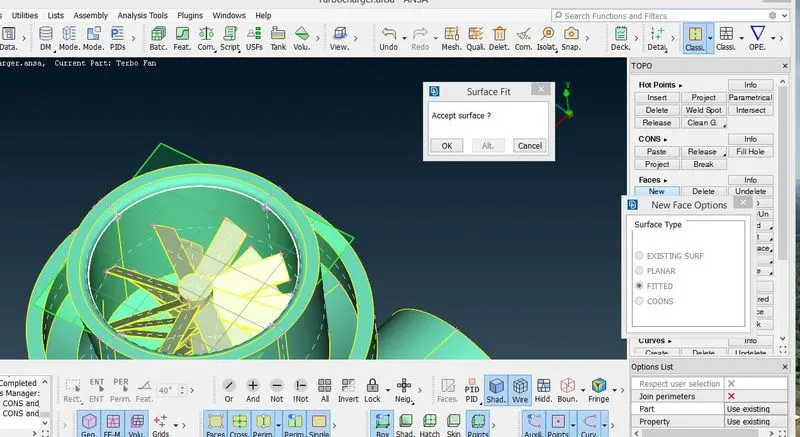
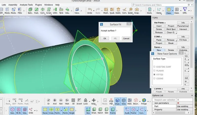
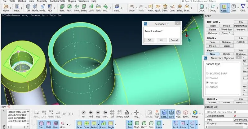
*Create surface using coons option where single cons are present.
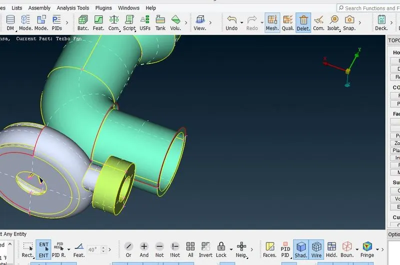
*For checking the errors we can use wireframe mode also in between.
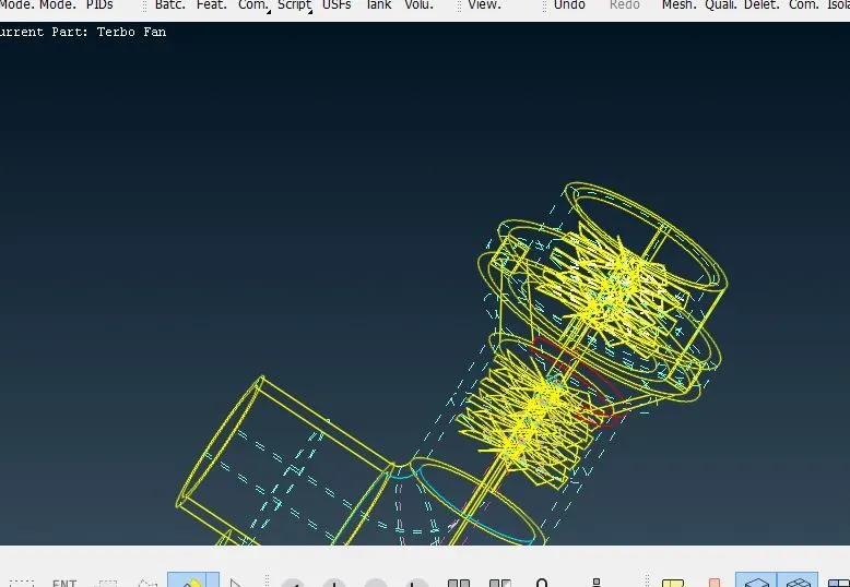
*While creating new surfaces there is a chance of distorting some surface boundaries;if there we need to correct that surface boundaries.
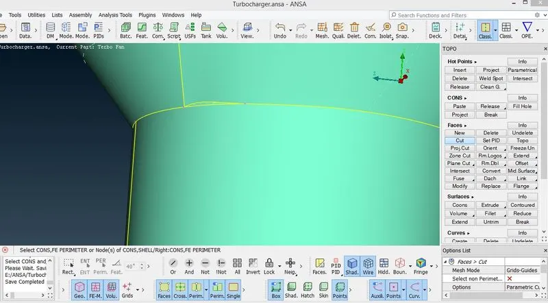
*In some areas we cannot use coons or fill hole option directly;if we are using that directly improper surface will create.
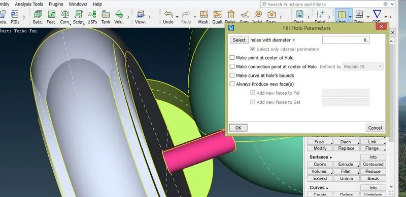
* In situations like this, we need to create extra hot points by parametric option and divide the area into small small areas and then create several surfaces there.Like this way we can create surface there.
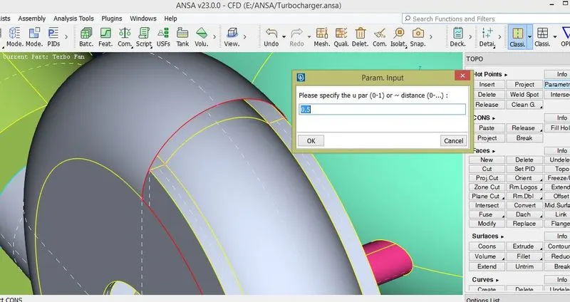
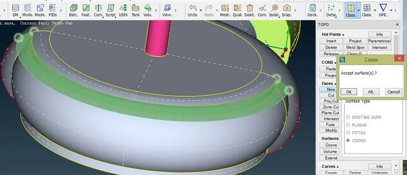
*Like this way we need to correct all geometrical and intersection errors in the inside parts also like in shaft, impeller and blades.
*For the easiness of correction of errors we can use NOT,INOT,OR ENTITY MODE, PID MODE,LOOP etc and also we can switch off some PIDs when that was not needed.
*In between we need to do geometric check, then only we can properly find how much errors are left in the geometry.
*So I am giving the images of that error correction below:
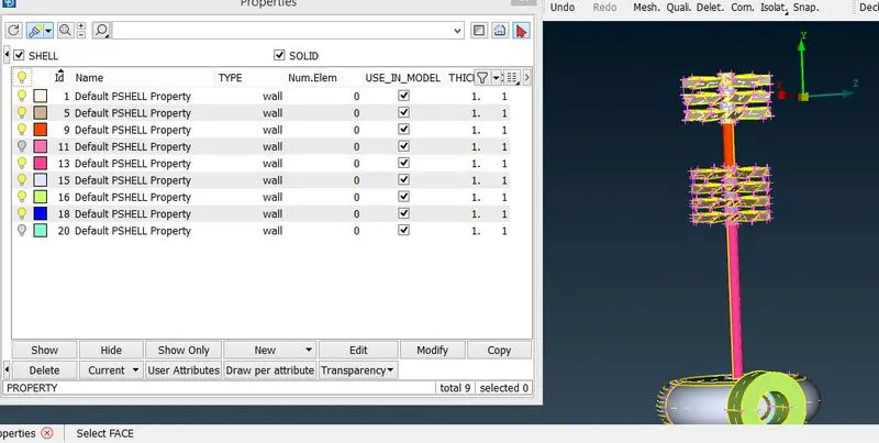
*The above pic shows hiding of unwanted PIDs for easiness of correction of errors.
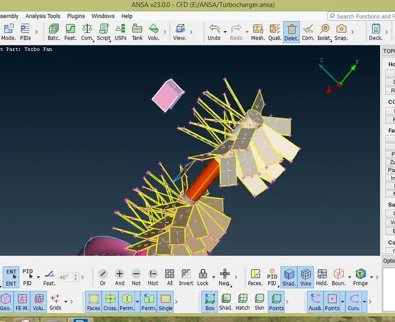
*The above pic shows deleting unwanted surfaces.
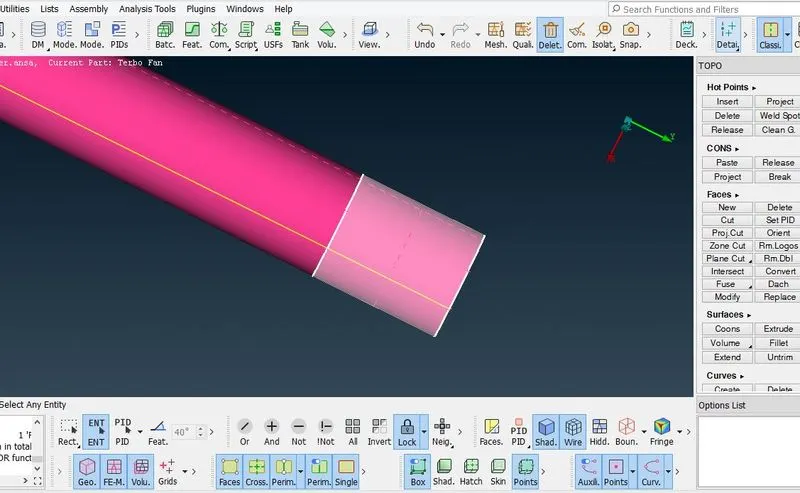
*The above pic shows deleting unwanted surface in the shaft.
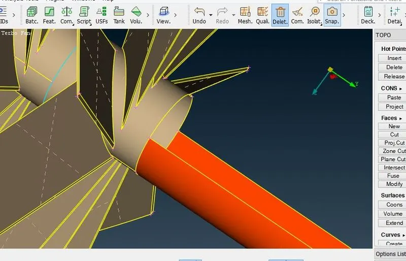
*The above figure shows deleting extra surface in the shaft.
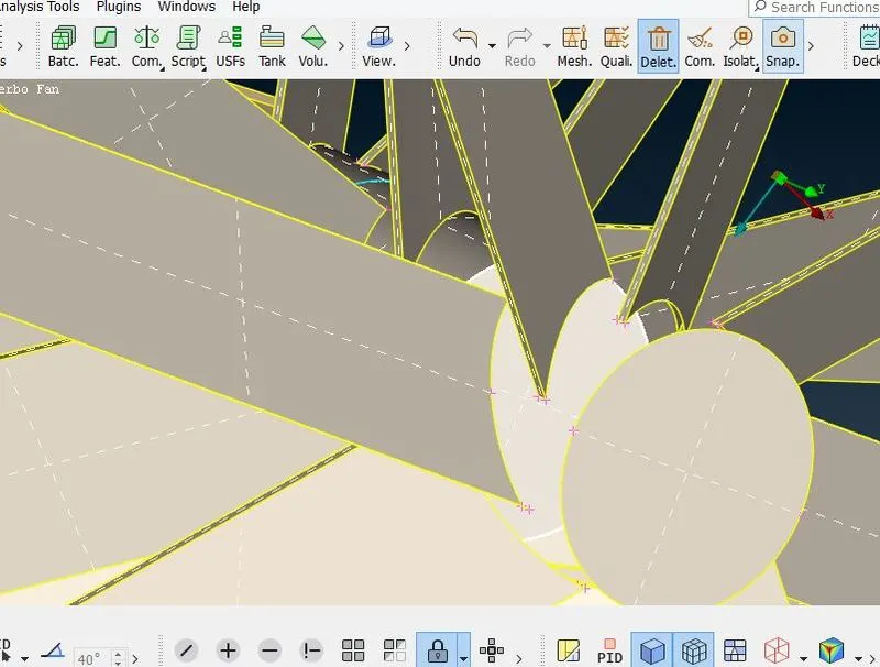
*There are several overlapped and extra surfaces are in shaft, so we need to delete all of that surfaces and need to make shaft as a single volume for meshing.
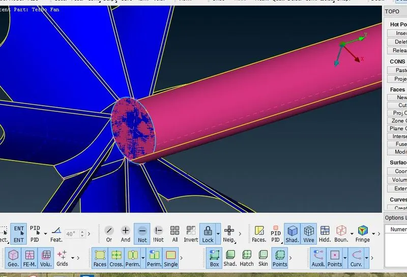
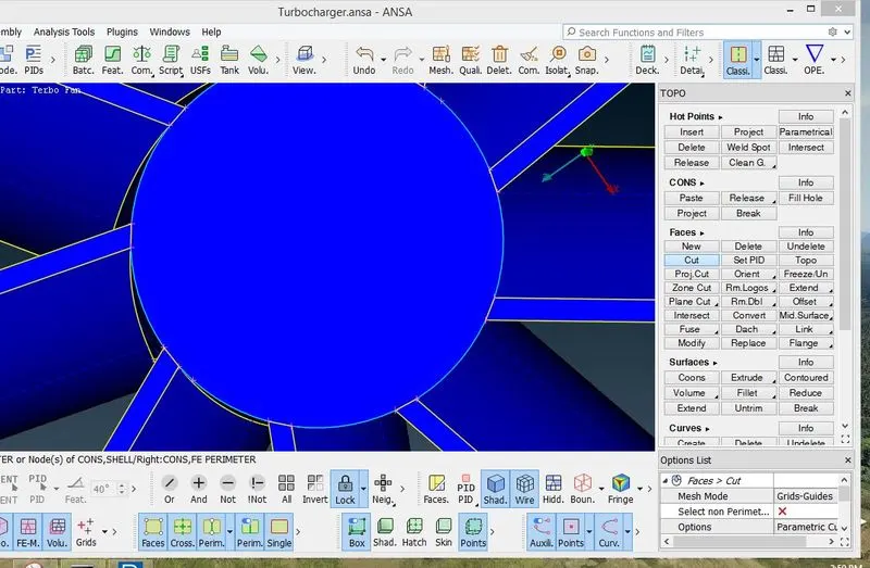
*The above figure shows isolating surface using cut option.
* 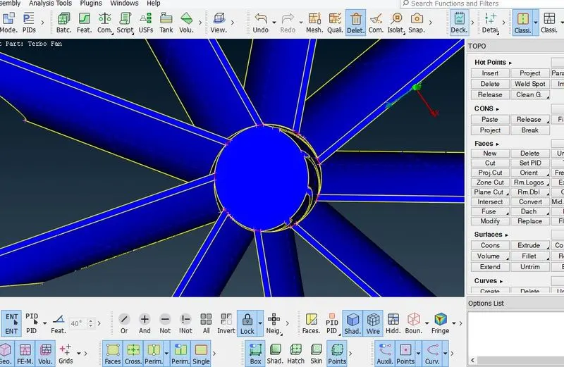
*The above figure shows After isolating, delete that surface
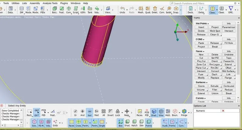
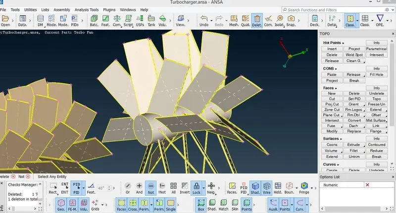
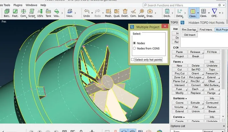
*The above figure shows projecting hot points.
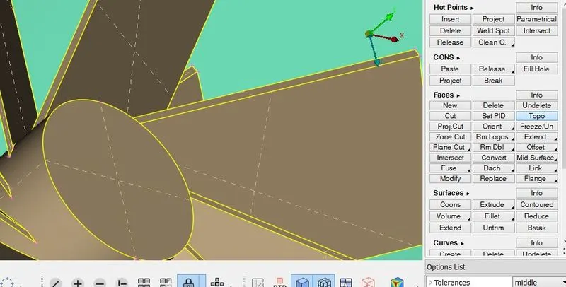
*The above figure shows using TOPO option for creating double con.
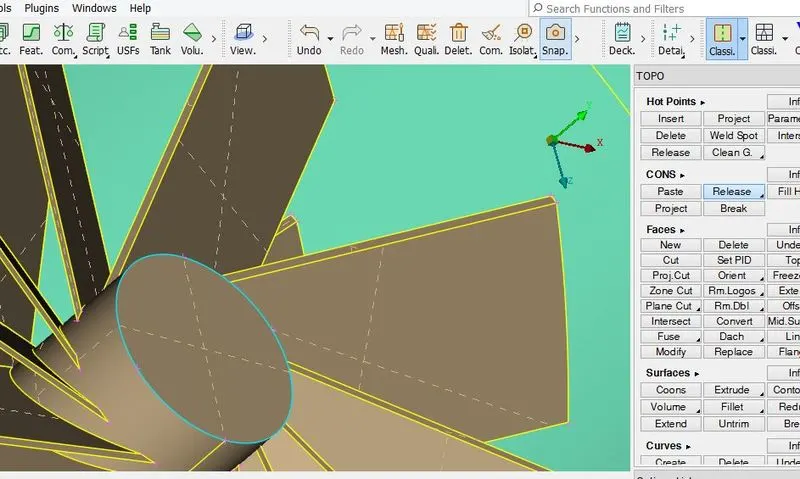
*The above figure shows using RELEASE option for removing tripple con.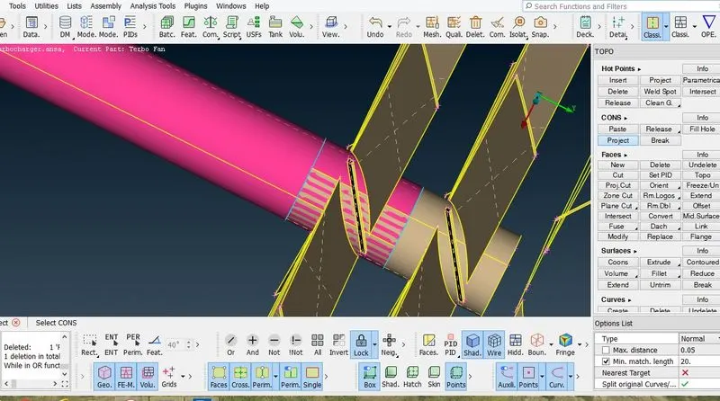
*The above figure shows using PROJECT option for projecting con.
*The above figure also showing using PROJECT option.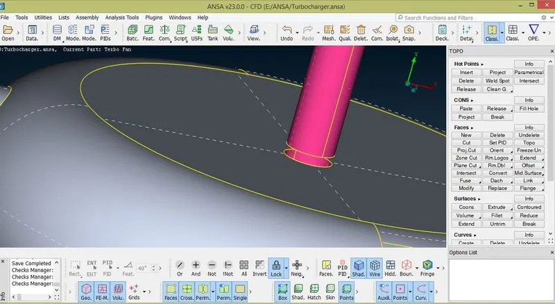
* The above figure shows the unwanted portion of the shaft deleted.
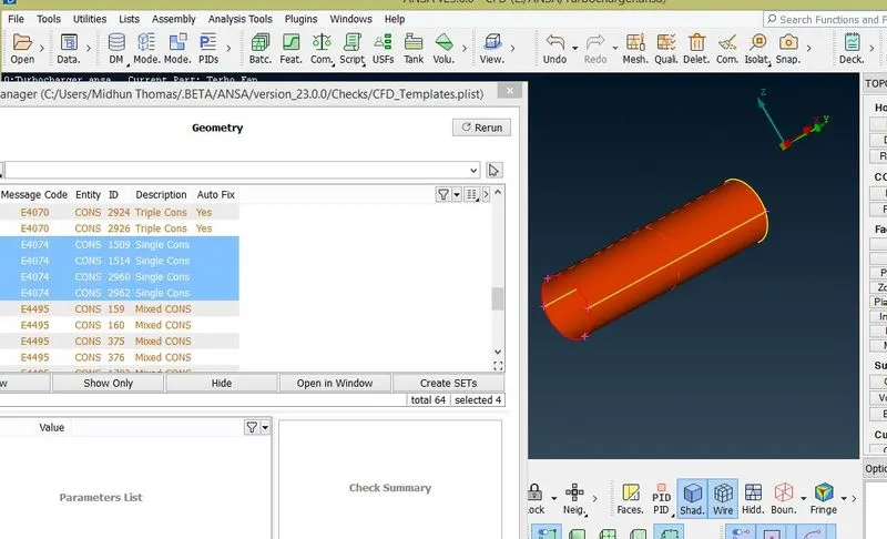
* The above figure shows some single cons while checking the geometry.
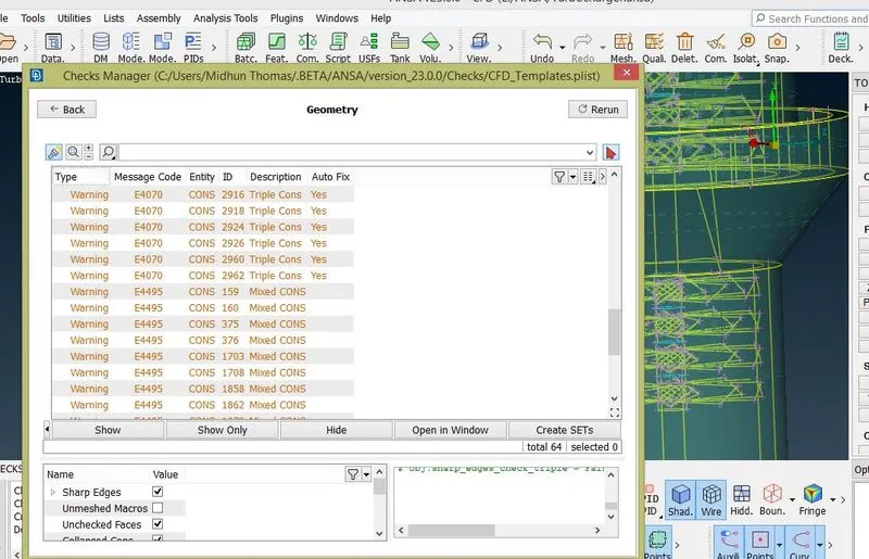
* The above figure shows now there are no single cons left in the geometry.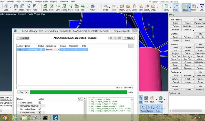
* The above figure shows there are no geometrical error left on the body.
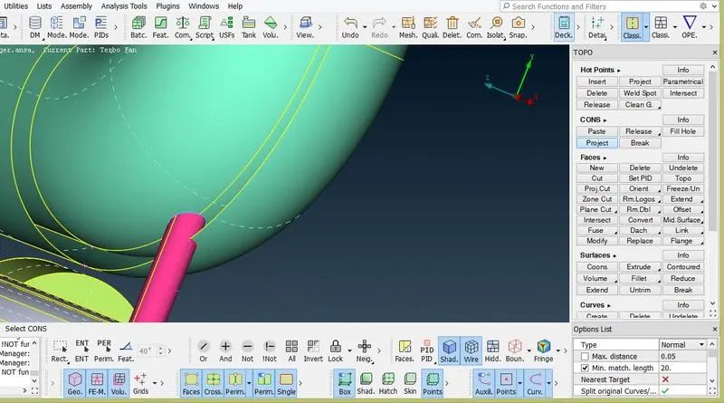
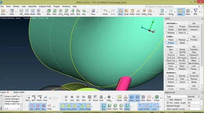
*The above figure shows projecting cons.
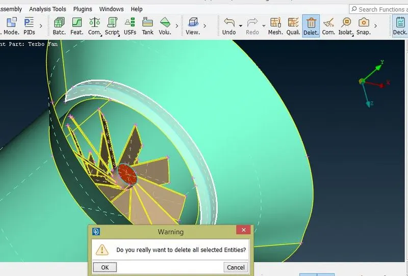
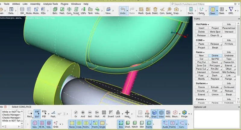
*Here also the figure shows the unwanted portion of the shaft deleted.
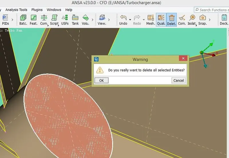
*After this much error correction we can do geometry check.Then it shows some intersection errors.
*So remaining intersection errors also we want to delete.
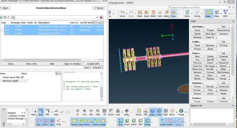
* The above pic shows some intersection errors.
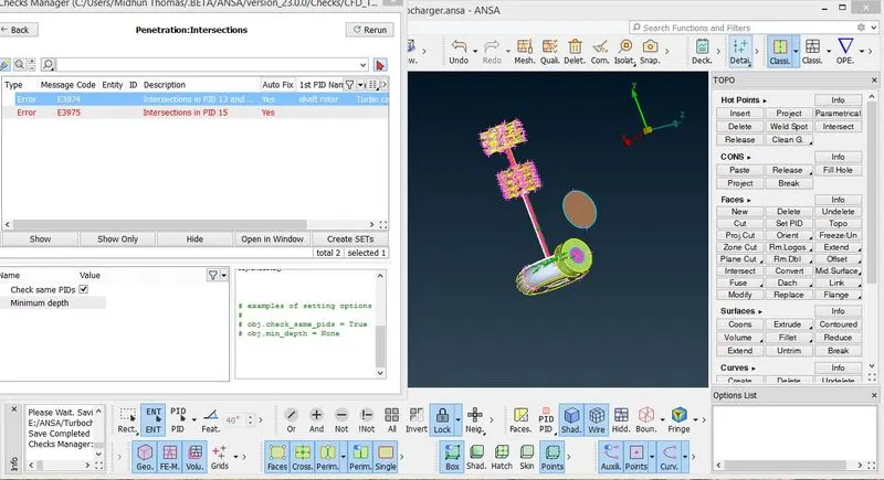
*The above pic shows there are only two intersection errors left.
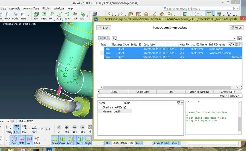
* The above figure shows there are three intersections on the full geometry.
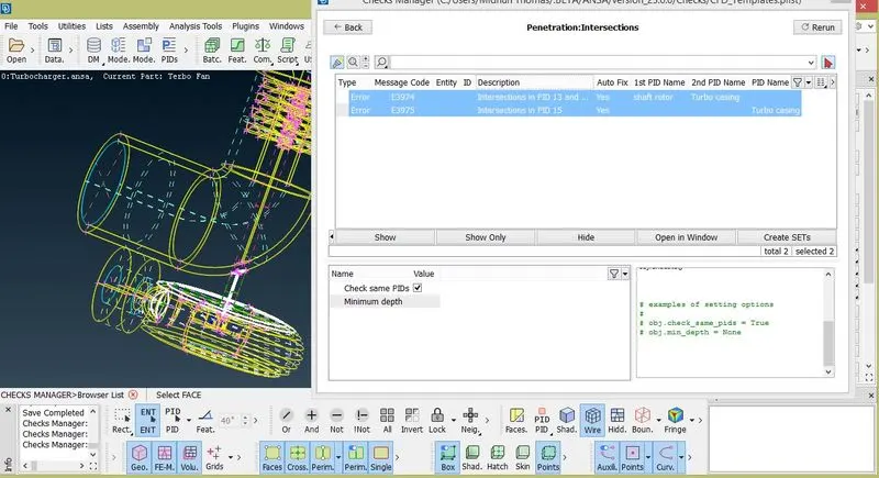
*Now the above figure shows only 2 intersection error are left on the full geometry.
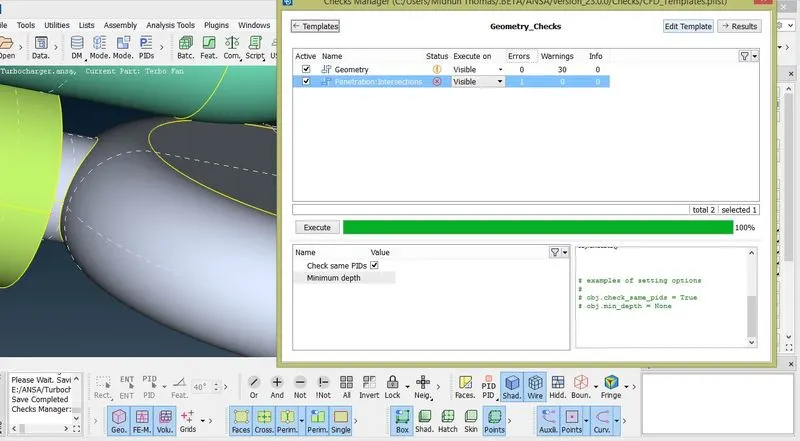
*Now only one intersecting error is left.
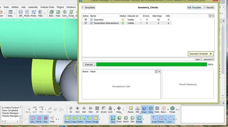
*Finally we removed all the interseting errors as shown in the above figure.
*Before doing surface meshing, we should close the geometry.
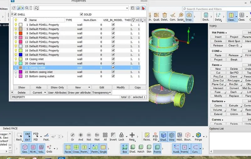
*After closing the geometry, we should assign PIDs properly for each part.
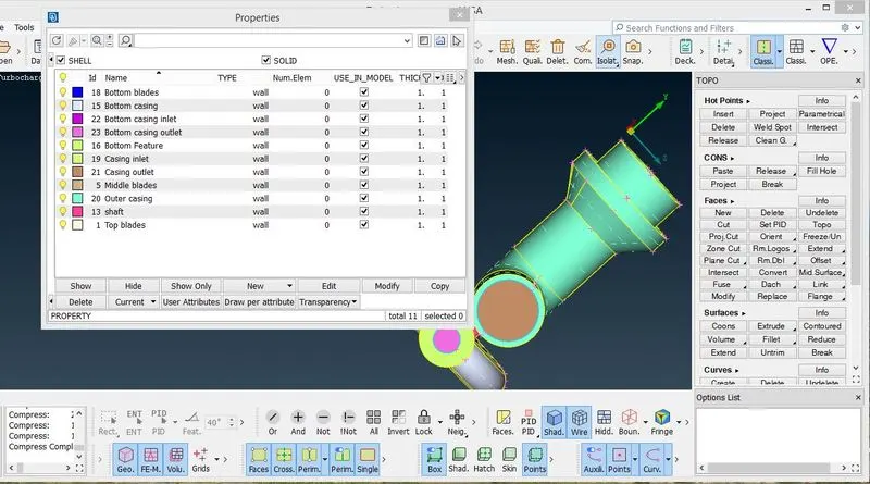
*Now we can do surface meshing.
*For doing surface meshing, we should check the target length of each part.
SURFACE MESHING OF COMPRESSOR CASING:
*For compressor casing, the target length is 5mm.
*We should give all mesh parameters based on that target length
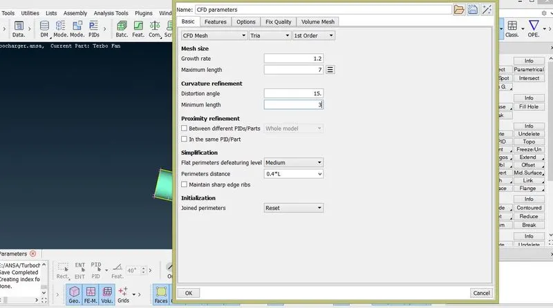
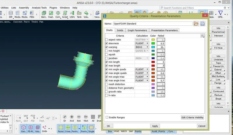
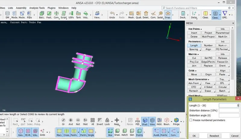
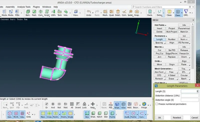
*After giving these parameters, surface mesh created on the compressor casing.
*For doing surface meshing, we used CFD mesh.
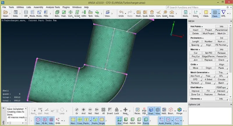
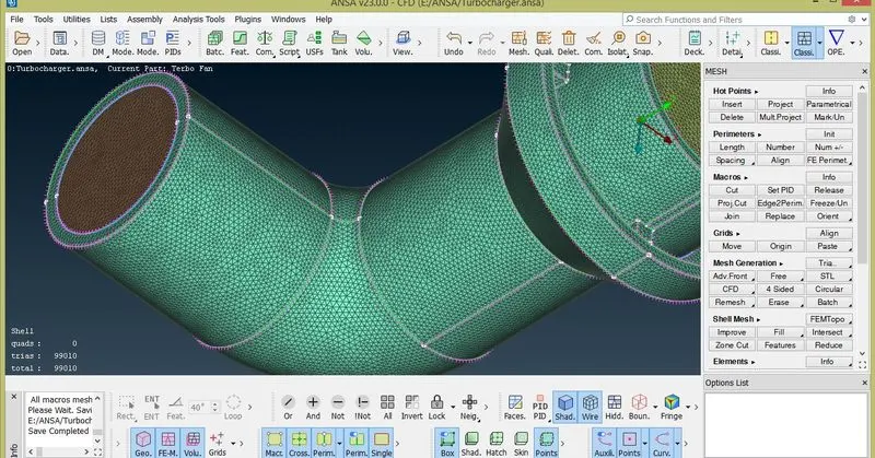
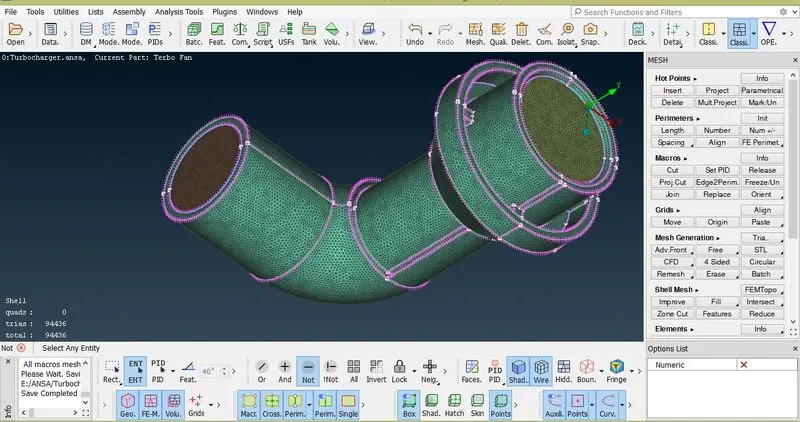
*The above figures shows surface meshing on compressor casing.
SURFACE MESHING ON TURBO CASING AND INLET COVER CASING:
*For this part also the target length is 5mm.
*Based on the target length we given mesh criterias.
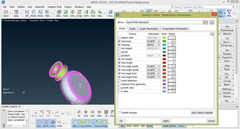
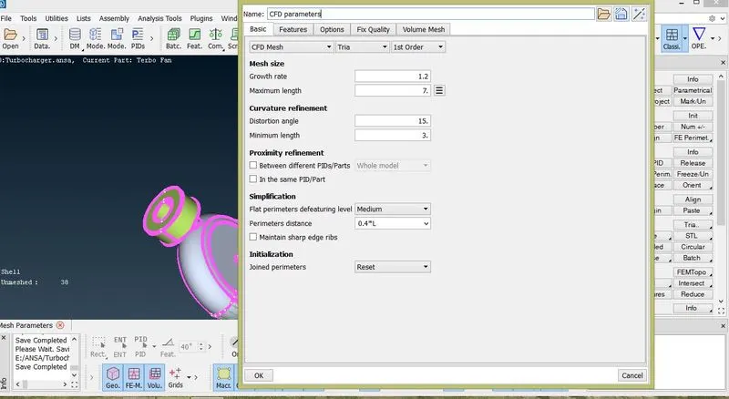
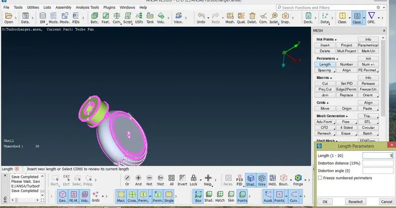
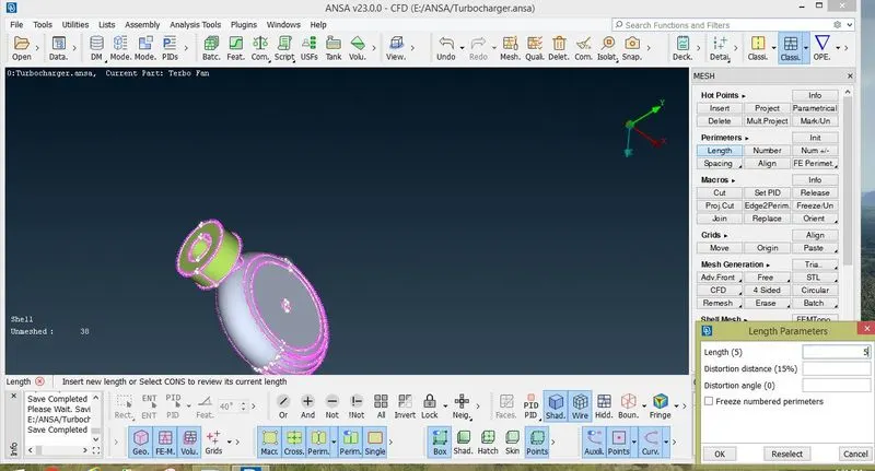
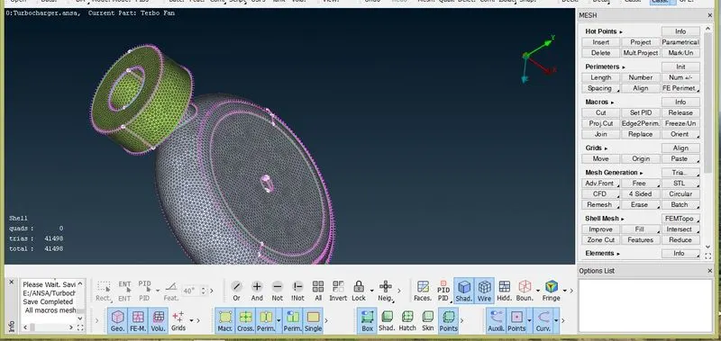
* The above figure shows surface meshing on Turbo casing and inlet casing cover.
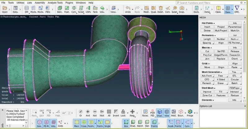
* The above shows the surface meshing on Compressor casing, Turbo casing and inlet casing cover.
SURFACE MESHING OF SHAFT ROTOR:
* For doing surface meshing on shaft, the target length is 1mm.
* Based on the given target length we given all mesh criterias.
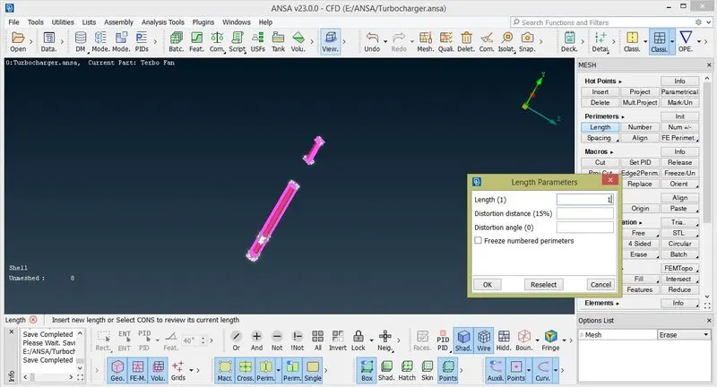
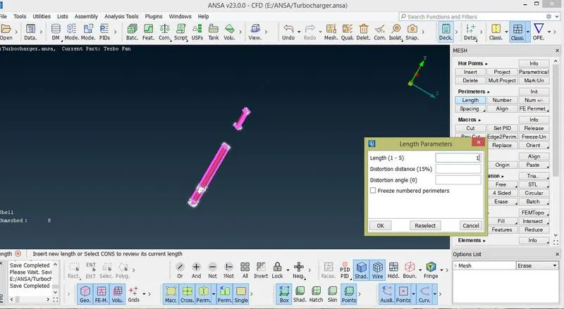
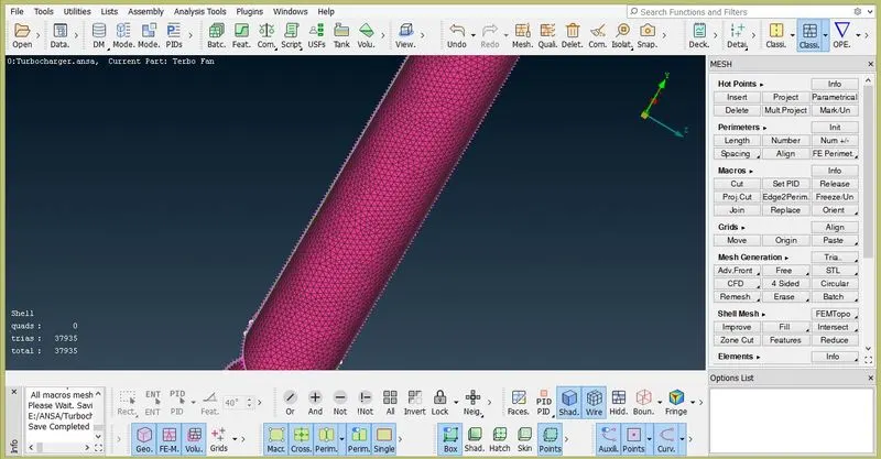
* The above figure shows surface meshing on the shaft rotor.
*SURFACE MESHING ON BLADE STAGE 1& 2:
* For doing surface meshing on the blade stage 1&2, the target length was 1mm.
*We given all mesh criterias based on that target length.
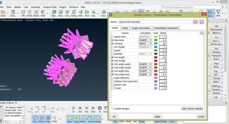
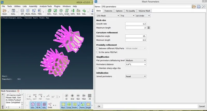
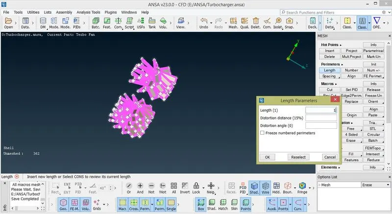
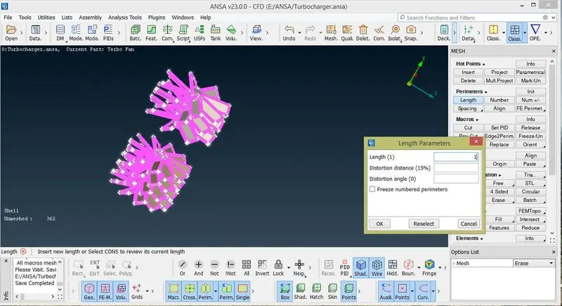
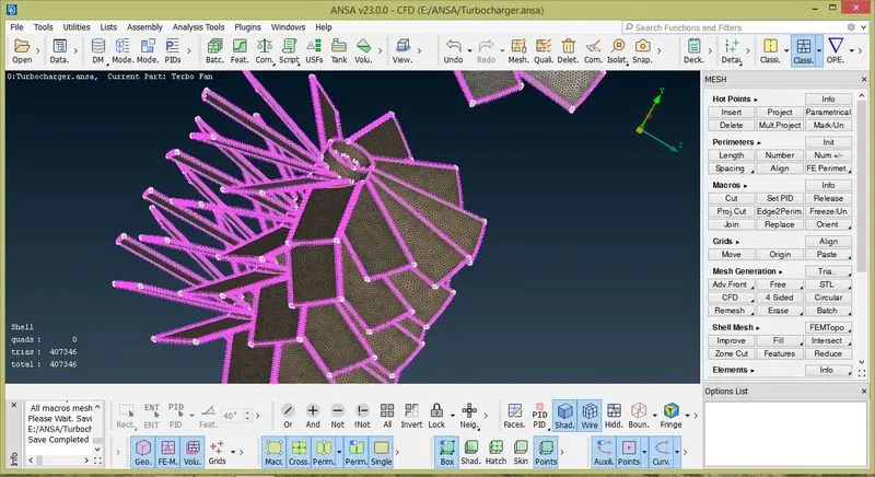
*The above figure shows surfce meshing on blade stage 1& 2.
*SURFACE MESHING ON THE IMPELLER:
*For doing surface meshing on the impeller, the target length is 2mm.
* Based on the target length, we given all mesh criterias.
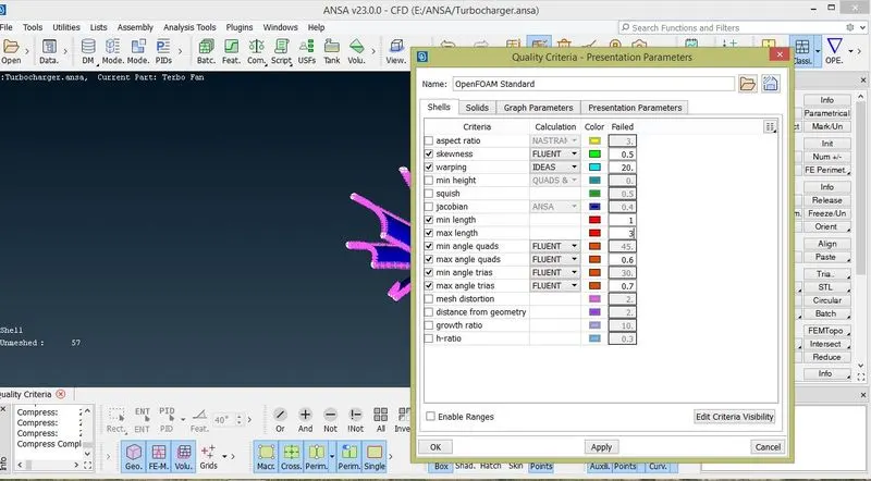
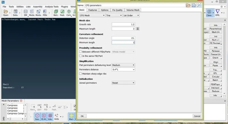
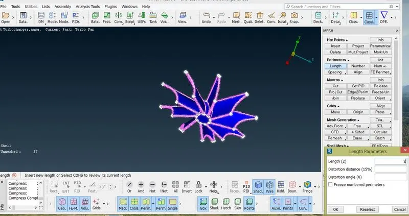
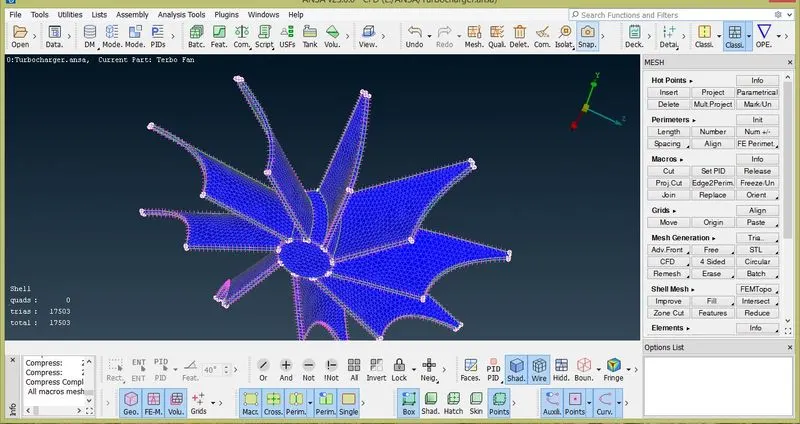
* The above figure shows the surface meshing done on the impeller.
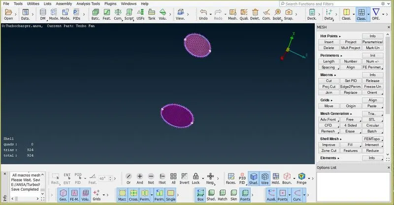
*The above figure shows the surface meshing done on the cover inlet & outlet.
* After doing the surface meshing on the all parts we could see that the meshing on some surface erased due to the sudden change in the target lengths.
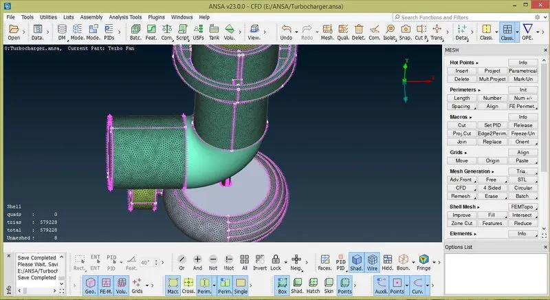
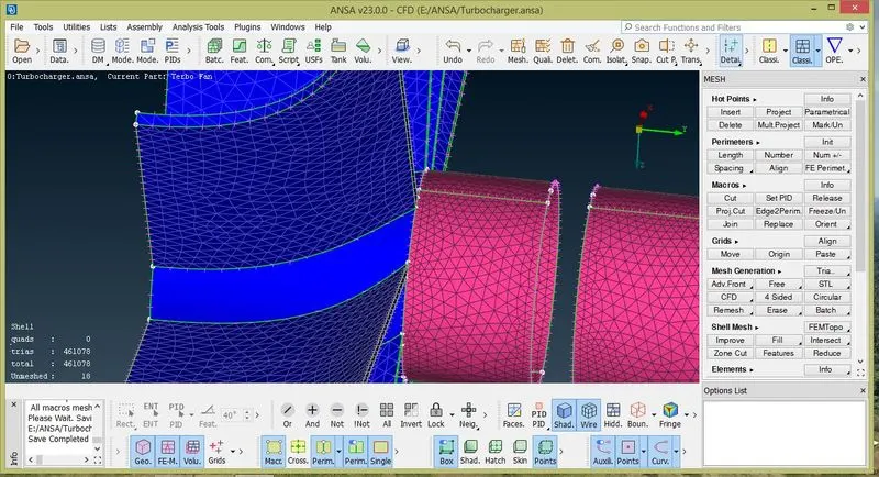
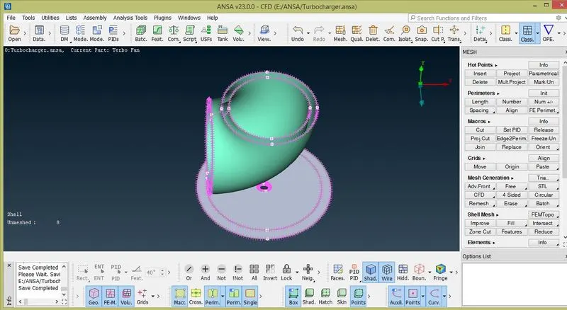
* The above figure shows that mesh from some portions erased due to the sudden change in the ytarget length.
* So I remeshed these portions and corrected these areas.
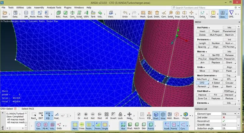
* The above figure shows the remeshing of shaft portion.
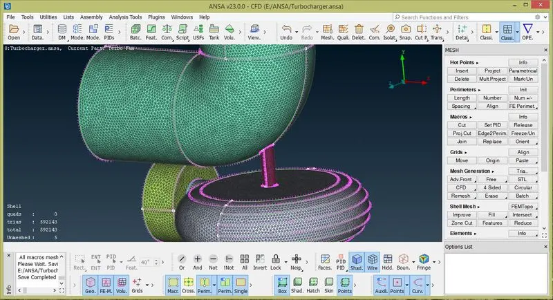
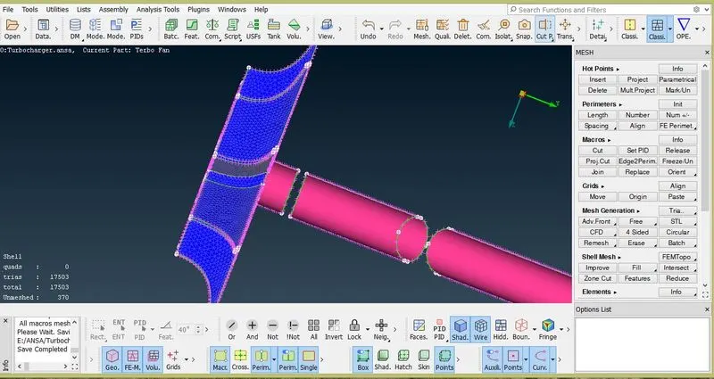
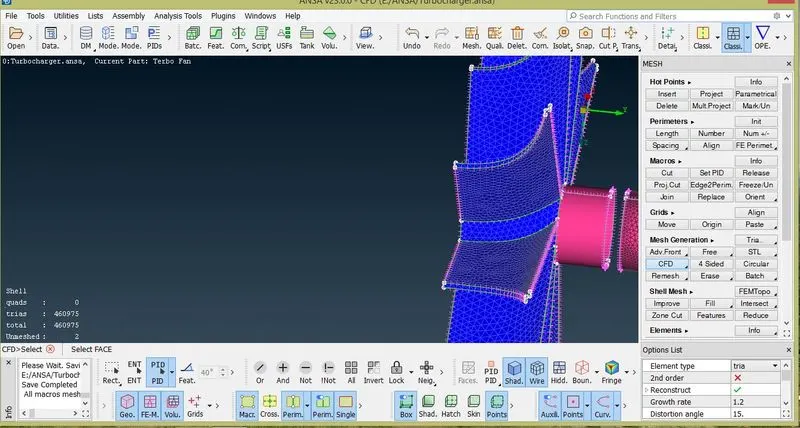
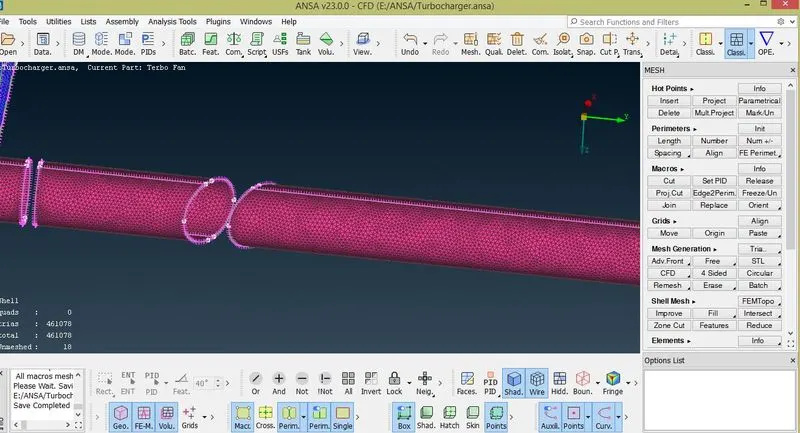
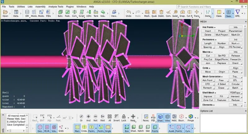
* The above figures also shows the remeshing of parts from where mesh erased due to the sudden change in the target length.
*Like this we finished surface meshing of all parts of the given geometry.
*Next step is doing volumetric mesh.
*VOLUMETRIC MESHING:
*For doing volumetric meshing first we need to change into volumetric mesh mode.
*Then by using 'DEFINE' option we can see the automated detected volumes by ANSA.
*After checking each volume, we need to delete unwanted volumes.
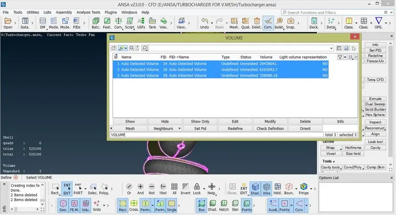
*The above figure shows deleted all unwanted volumes.
*We should do volumetric meshing on all volumes present there.
* For doing volumetric meshing, we need to select each volume seperatly.
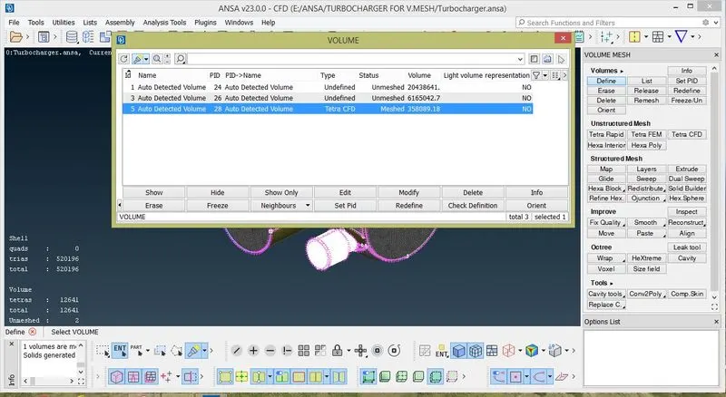
*Like this way, we need to select all volumes and do volumetric meshing
*For doing volumetric meshing I selected Tetra CFD elements.
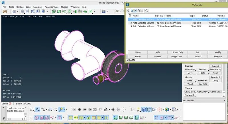
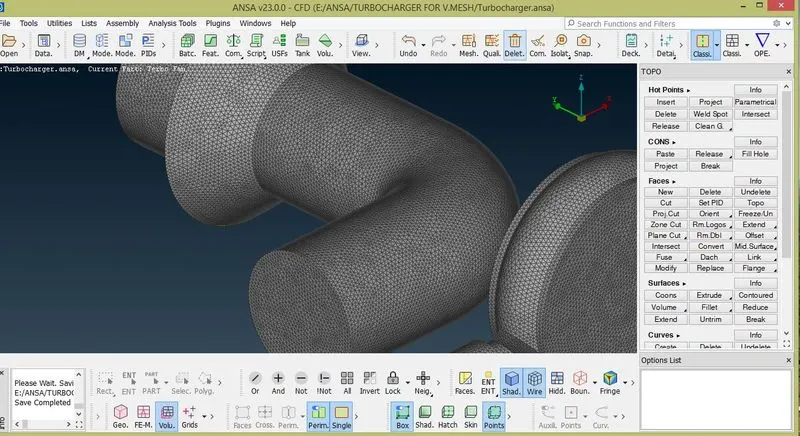
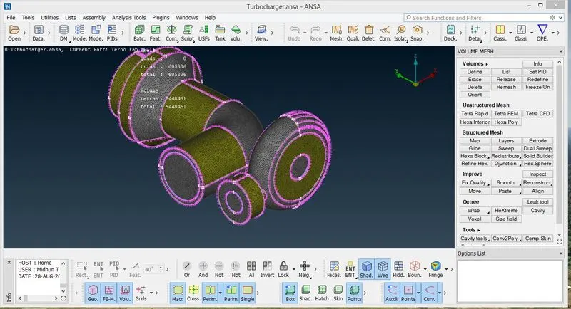
*The above figures shows the volume meshing done on whole geometry.
*We can see the cross section view of volumetric meshing also.
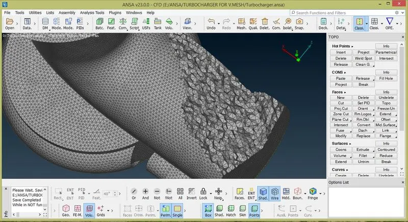
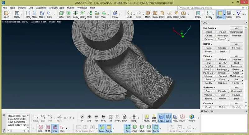
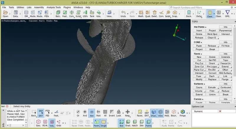
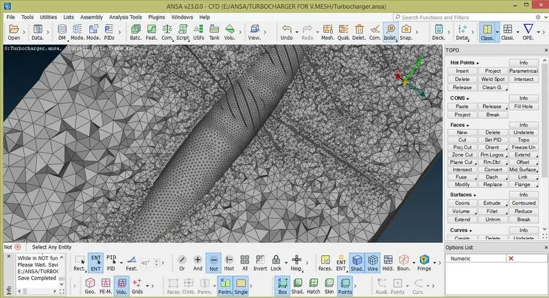
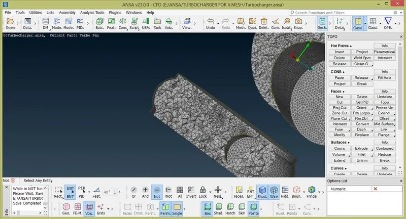
*By selecting a new cutting plane also we can see the cross section view of volumetric meshing.
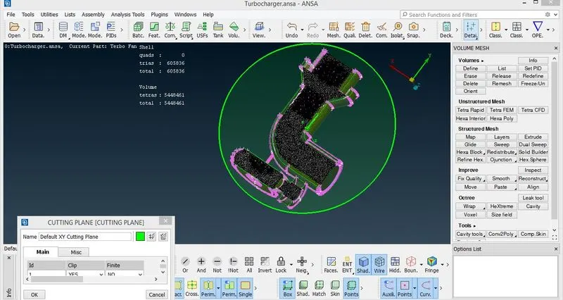
* Like I could finish the volumetric meshing of Turbo charger.
* Sorry, I can't upload the final geometry file, So final geometry file I inseted as google link for that below.
LEARNING OUTCOMES:
* I could learn so many things by doing this project
* I learned how to solve different types of geometrical errors.
* Learned hoe to do surface meshing with diffrent different target length.
* Learned how to create mesh on erased parts.
*Learned how to create volume mesh.
* Learned how to delete unwanted volumes.
* Learned how to check volumetric mesh by craeting cutting plane.
RESULT:
*Done surafce meshing on each parts with given target length
* Done volumetric meshing on the given geomery with Tetra CFD elemets.
COCLUSION:
* In coclusion, I could learned how to create surface mesh with different target length and also I learned how to do volumetric mesh. Here on the given geometry I created surface mesh with given target length and created volumetric mesh also.
Final Geometry File:https://drive.google.com/file/d/1hMsya-nzDIeKLZtgDgKEGGnipQPO8SL6/view?usp=sharing