Week 3 Challenge : CFD meshing on Turbocharger
CFD meshing on Turbocharger
AIM:
For a given model of a turbocharger check for the geometric errors to make appropriate volumes. create and assign PIDs accordingly also create a surface mesh and use that to create a volumetric mesh.
OBJECTIVE:
-Performing surface mesh with given target length as per PIDs.
blade stage 1 = 1mm
blade stage 2 = 1mm
impeller = 2mm
shaft rotor = 1mm
turbo casing = 5mm
compressor casing =5mm
inlet casing cover =5mm
writing the detailed report on your surface meshing and volumetric mesh.
STEPS:
-import turbocharger model:
initial model:
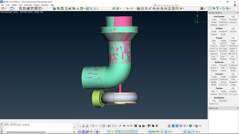
- start the topo clean by doing a geometry check to find single and triple cons in the geometry
-delete the unnecessary overlapping surface by using the universal delete option.
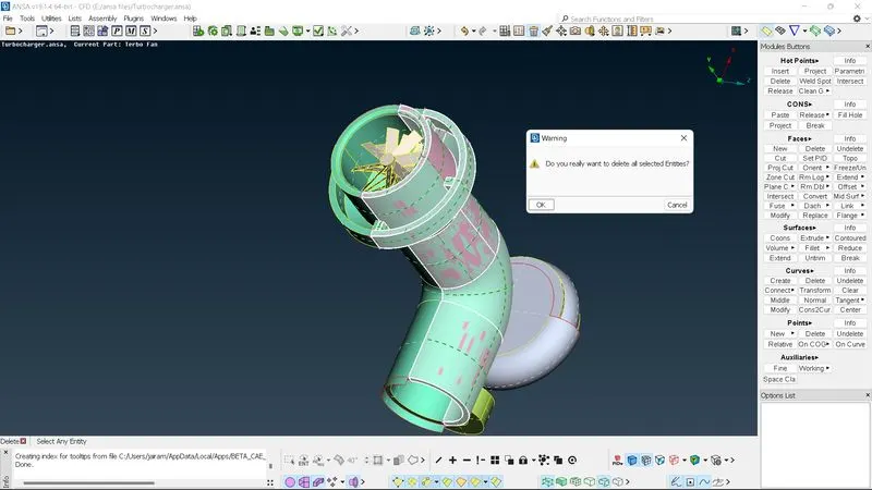
start filling the surface and cleaning the single cones by creating the surface where ever required.
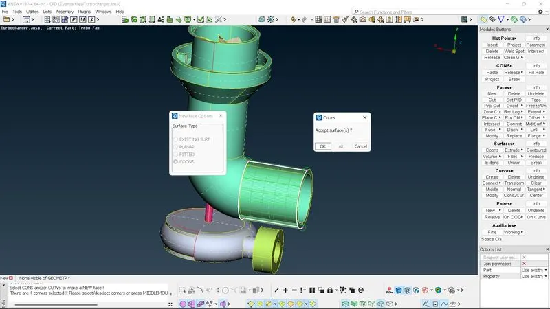
- In certain areas use transform options like mirror faces
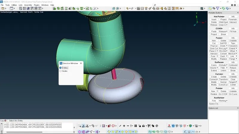
and also use fillhole option
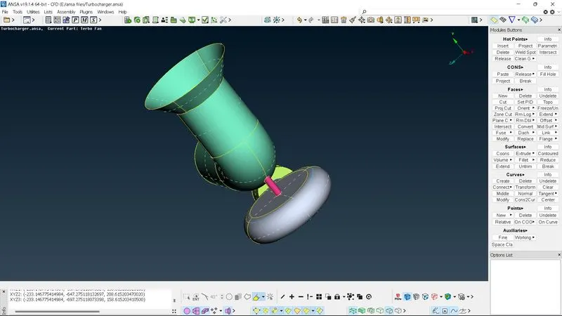
- here we use intersect option to delete the surface which has no separate entity, therefore separate entity is formed and can be deleted it easily after that.
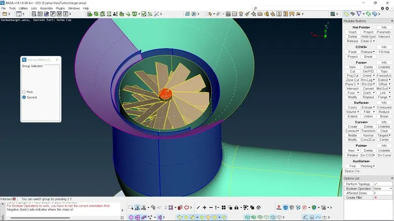
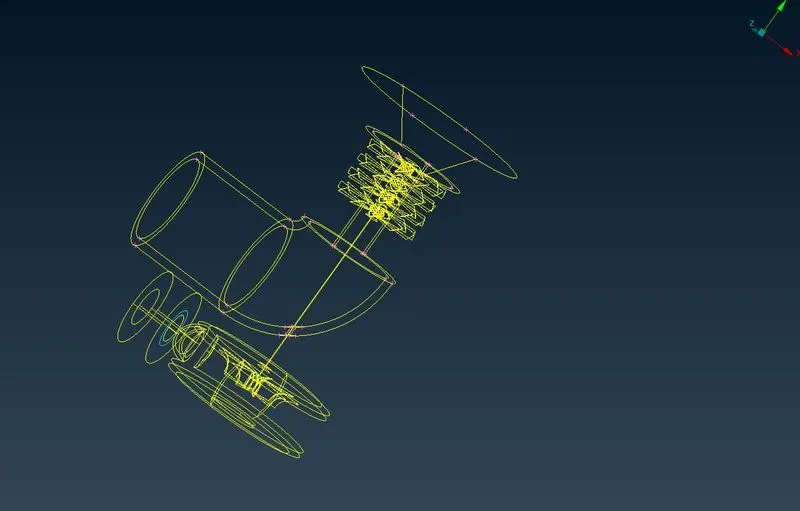
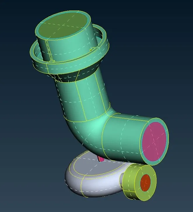
the blue circle indicates triple cons these cons are not errors and are required to make the geometry water-tight.
before going to meshing we just check the geometry for any errors apart from triple cons this can be done using check manager in to top toolbar go into geometry and execute it.
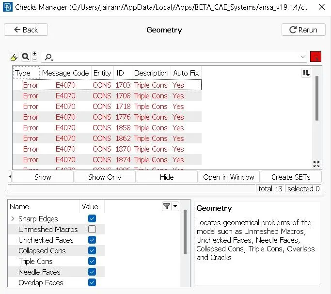
And close all openings
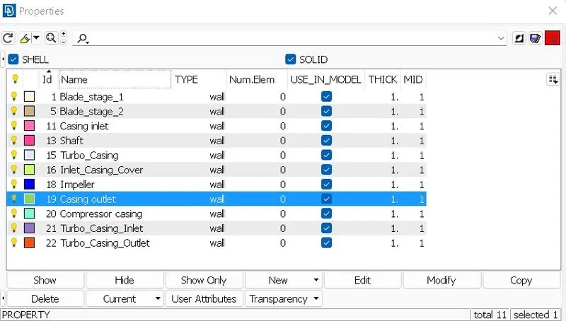
Assigning relevant PIDs
to check the surface and to assign PIDs click on a surface that you want to assign and make the wire option enabled. and click on the list and then click the middle button to assign new PIDs. also, repeat the same for other PIDs.
Now surface meshing:
select the mesh module and then the parameter in length
before that put the max and min limit in mesh quality.
drag the cursor to cover the entire model and click the middle mouse button to give the mesh size as 5mm for the entire model.
the entire mesh model has meshed with the appropriate mesh size.
here we have a mesh of individual parts:
blade stage 1 = 1mm
blade stage 2 = 1mm
impeller = 2mm
shaft rotor = 1mm
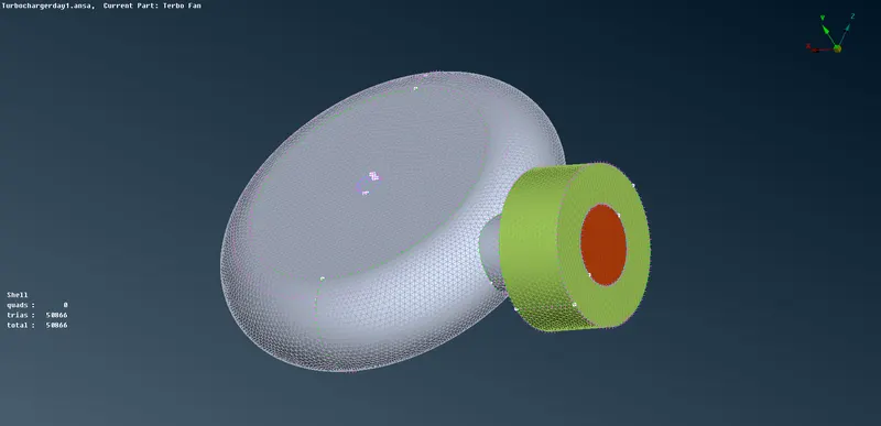
turbo casing = 5mm
compressor casing =5mm
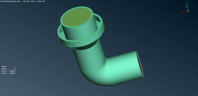
Target length= 5mm
compressor casing
Turbo casing
Target length= 2mm
Impeller
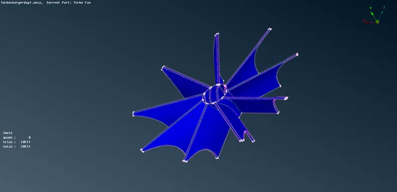
Target length= 1mm
Blade stage-1, Blade stage-2, and Shaft rotor
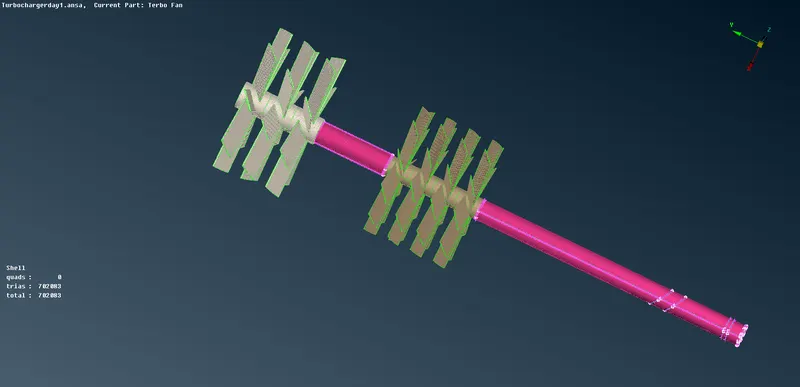
Meshed geometry
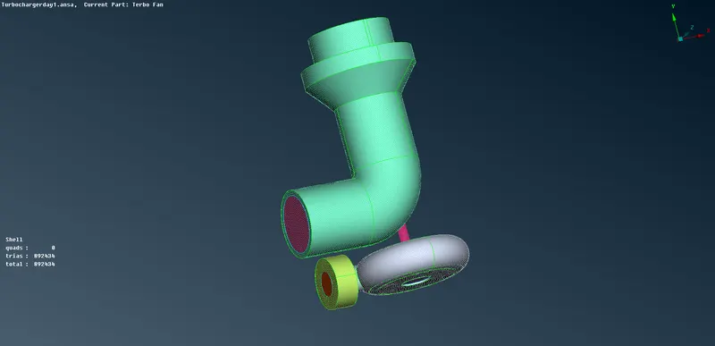
in some areas where the shaft meets the component having different target lengths, the mesh adopts such that there is a connectivity between the two components.
VOLUMETRIC MESH:
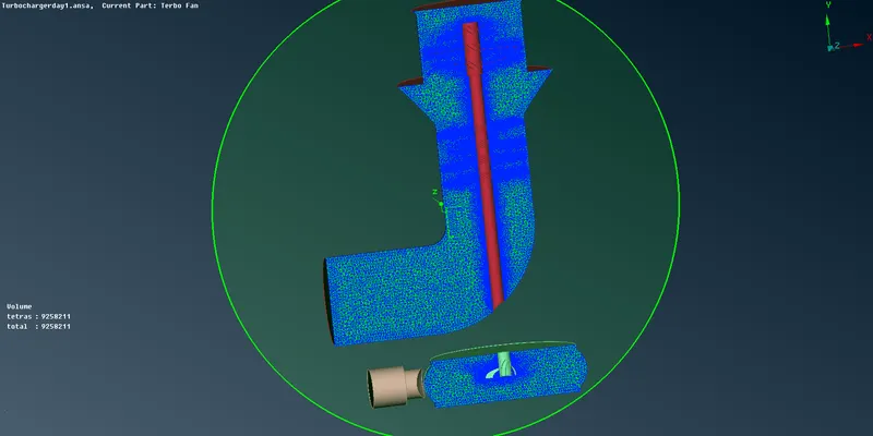
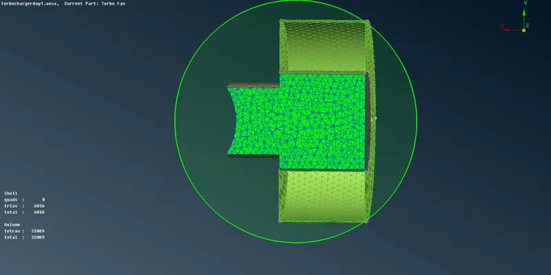
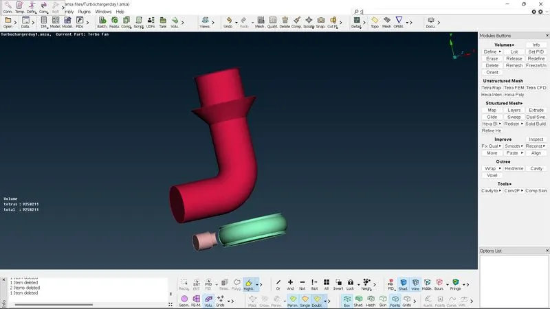
For volumetric mesh, we go to the right side menu, and in the volume, define use the entire database and press ok.
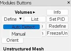
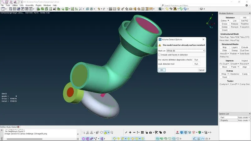
in that it will detect a total of 8 volumes in those volumes we need only 3 volumes the fluid region volume not the thickness of the component.
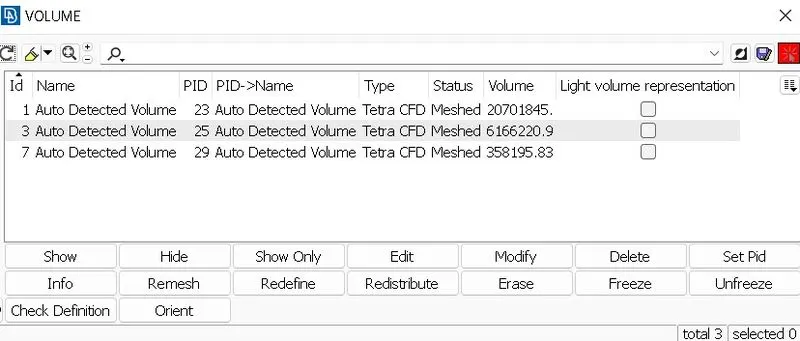
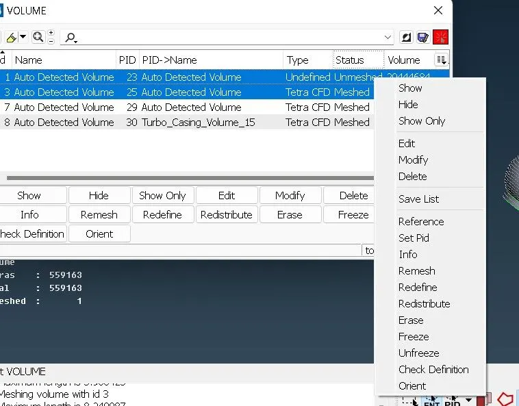
select volumes the fluid right click -->Remesh--> select Tetra CFD
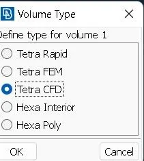
generate the volume tetras.
so finally we have done:
- checking the geometry error and correcting the geometry using different geometry editing tools.
- deleting overlapping regions to improve mesh quality and avoid volume meshing
- correcting the triple cons and single cons, giving the finer mesh
- creating the surface mesh individual, and also maintaining mesh length range at the contact region between 2 different mesh lengths.
- creating the volume mesh only for the fluid region.
CONCLUSION:
The given geometry is volumetric meshed to have tetra elements. all the mesh elements have been surface meshed while only the fluid region has been volumetric meshed.
Model Results ANSA file:
https://drive.google.com/file/d/1fksEQQr-BFkI0qbNmq3thqtdbD-JCTur/view?usp=sharing