Week 3 Challenge : CFD meshing on Turbocharger
Week 3 Challenge: CFD meshing on Turbocharger
AIM:
For the given model, check for the geometrical errors to make appropriate volumes. Create and assign PIDs and, perform surface mesh with the given target lengths as per PIDs.
- Blade stage-1 = 1 mm
- Blade stage-2 = 1 mm
- Impeller = 2 mm
- Shaft rotor = 1 mm
- Turbo casing = 5 mm
- Compressor casing = 5 mm
- Inlet casing cover = 5 mm
Perform Volumetric mesh for the required volumes.
GIVEN MODEL:
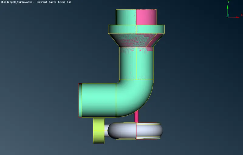
Side View
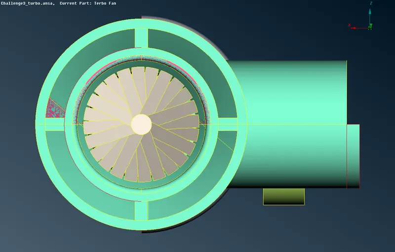
Top View
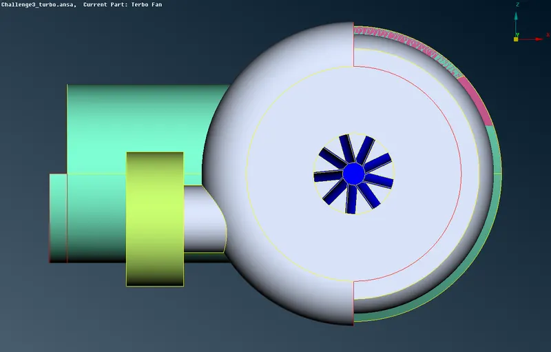
Bottom View
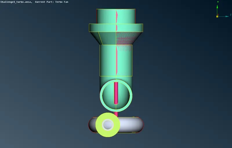
Front View
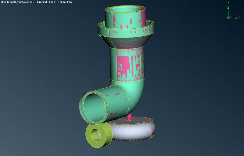
Isometric View
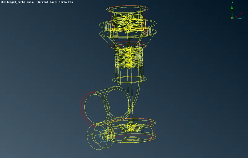
Unshadowed Iso-view
TOPO Cleanup Procedure:
- As we see the model given has many single cons, we want to do some Geometry checks to explore what are the errors we are encountering here,
- SINGLE CONS- the edge which is shared by only one surface.
- DOUBLE CONS- the edge which is shared by two surfaces.
- TRIPLE CONS- the edge which is shared by three surfaces.
- And the model has some overlapped surfaces which have to delete to reduce the error during the meshing process.
- We have to check the triple cons also, in which region they are needed or not.
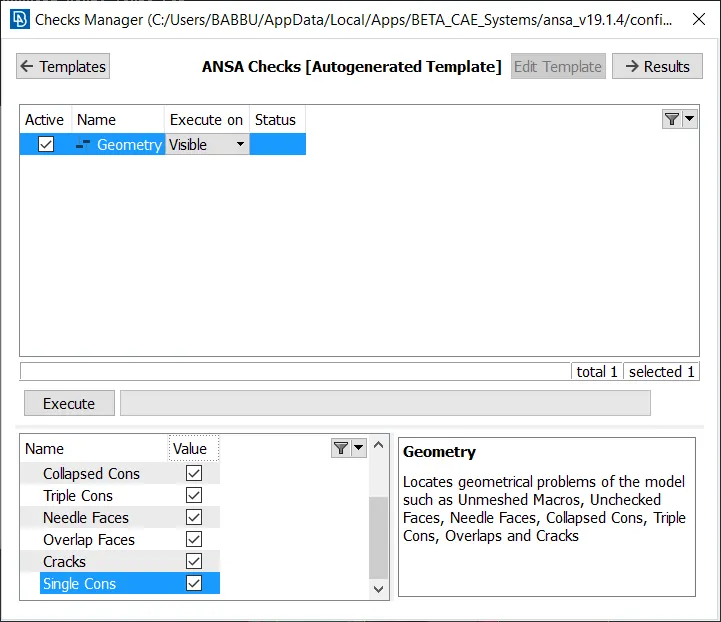
While performing a geometry check in the given geometry, we are getting multiple errors such as triple and single cons, overlapping surfaces as we discussed above,
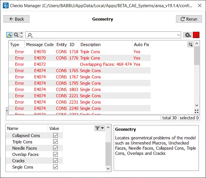
- And the errors are highlighted in white color as shown in the below picture.
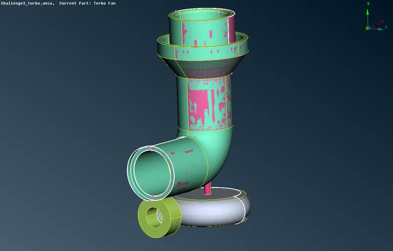
- As we have to remove the errors from the geometry to proceed with the meshing process, we have multiple tools to do so.
- First, we will see, how to delete the overlapped surfaces.
- Use the universal delete option to delete the surfaces.
- Enable the cross-hatches option in the geometry to select the surface easily which we want to delete.
- Use the PIDs selection tool to select a complete region in one shot, after selection delete the overlapped surface, as shown in the below pictures.
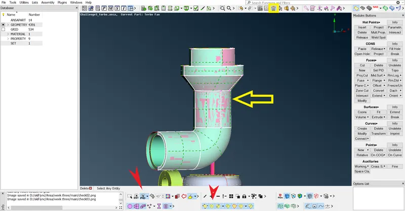
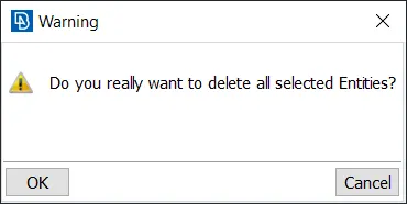
- As we can confirm deleting by clicking ok in the above window.
- Then the surface glitches have been removed from geometry as shown in the below picture.
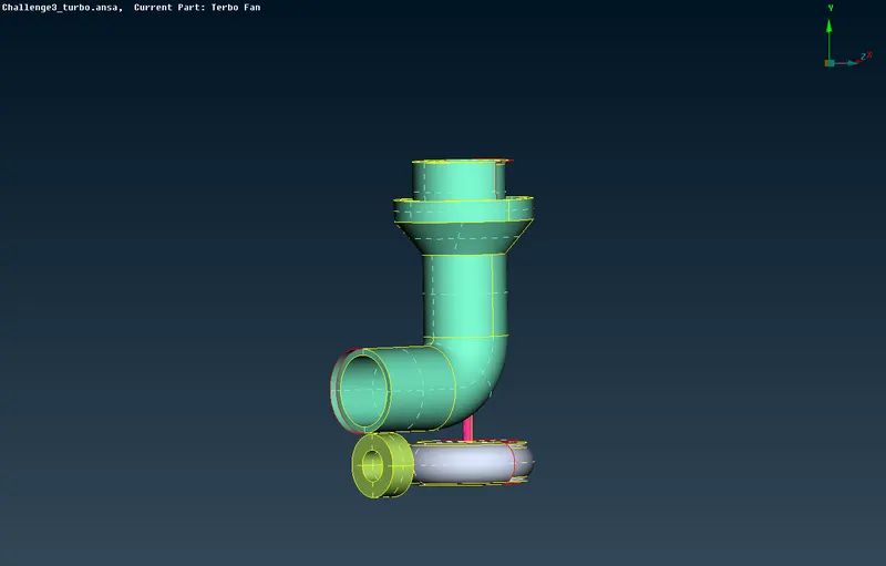
- We have to use the same steps to remove the all overlapped surface in the entire geometry.
- After we have done with the overlapped surface, we are going to deal with single cons and going to rectify the errors.
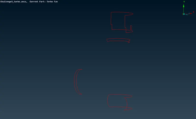
- These much of single cons have to be rectified, we can use multiple tools to so.
- some of the tools are fill hole, new surface....
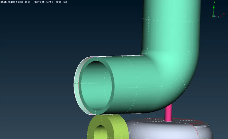
- first, we have to delete the extra surface which we don't need here.
- After deleting it we end up with an open loop of surface which we can use the fill hole tool to cover up as shown in the below picture.
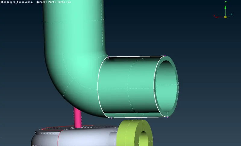
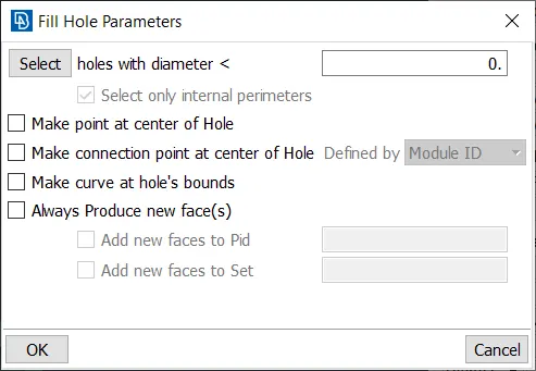
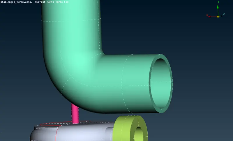
- Moving to another con, here we have to create a new surface first then use the fill hole option.
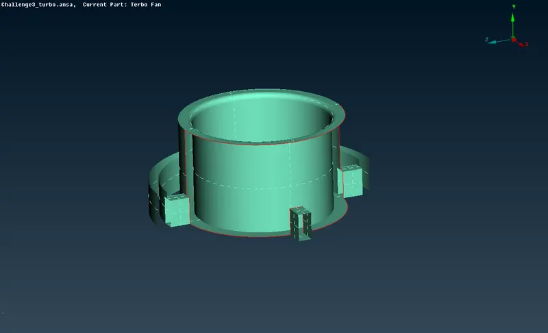
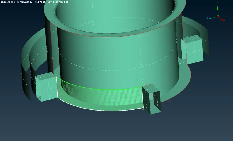
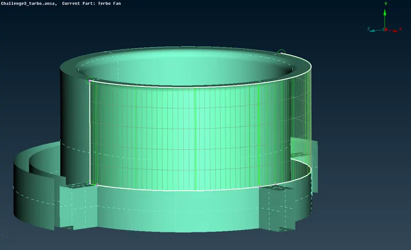
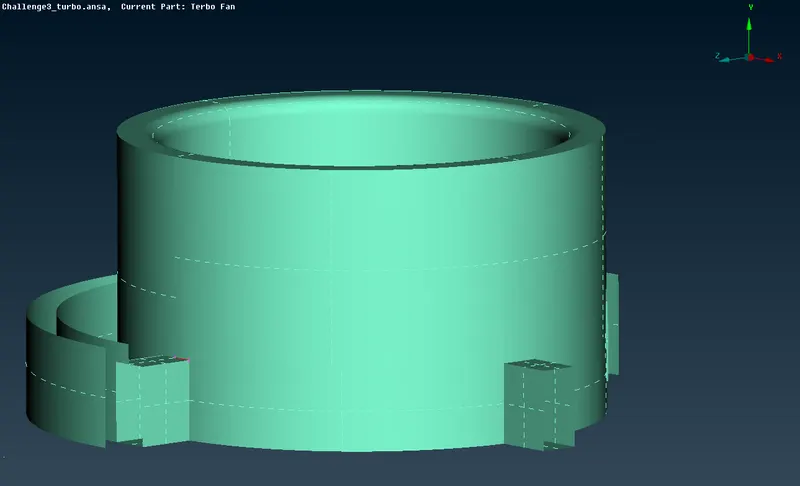
- Similarly use the above steps to make the single cons get eradicated from the geometry.
- Generate the Hot points as shown in the below picture.
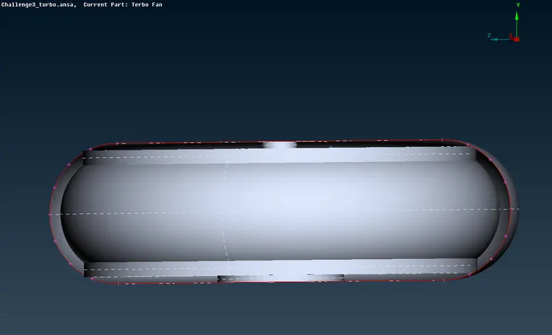
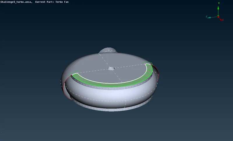
- Create new surfaces, such that it is sufficient enough to close the opening without any modification in the geometry.
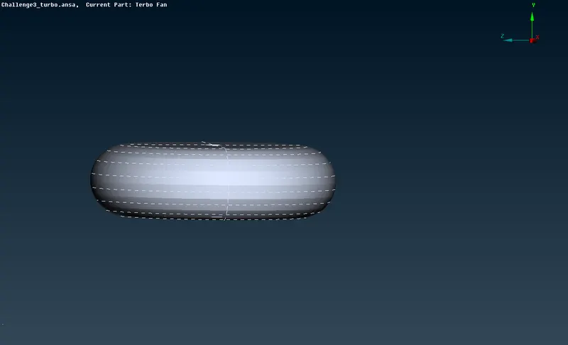
- Moving to the triple cons, examine whether it is needed in the geometry or not and decided to keep it or not.
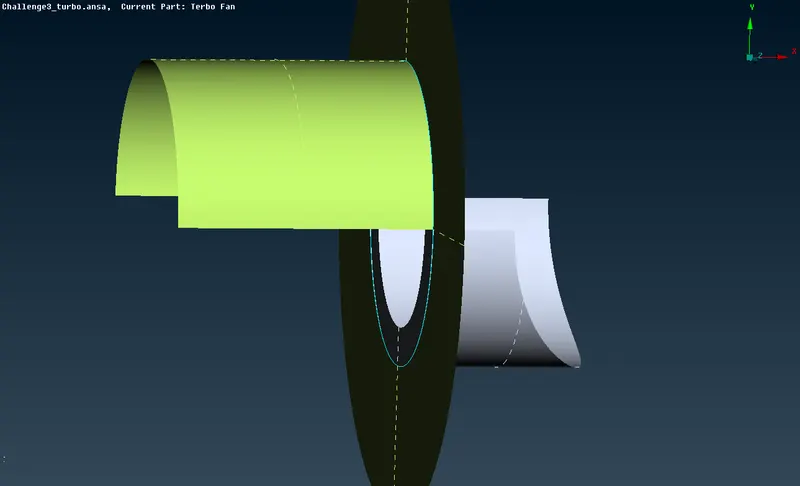
- As we can see in the above picture that this triple con is necessary for the geometry. So, we are going to keep it in the meshing part.
- By this step we are completed with the TOPO cleanup procedures, we can proceed with the meshing process.
- Close all the openings in the geometry to perform the volumetric meshing.
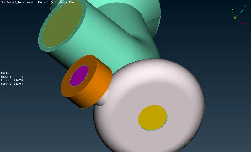
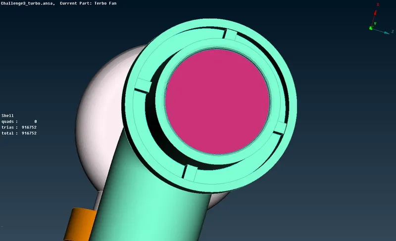
Boundary Flagging:
- Before the meshing process, we have to name the PIDs (boundary) individually, as shown in the picture.
- Create a new PSHELL for every single PID.
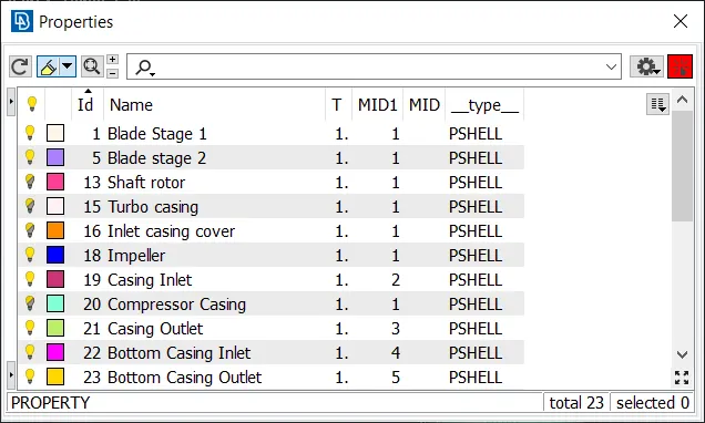
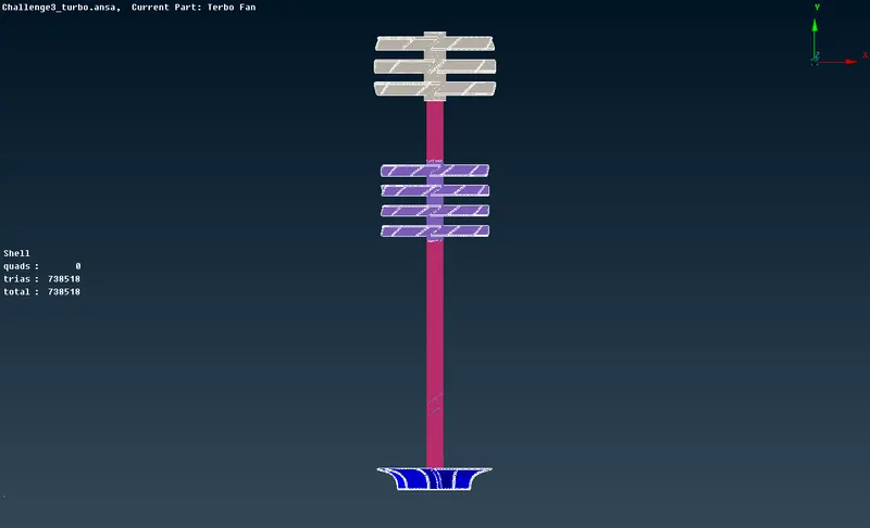
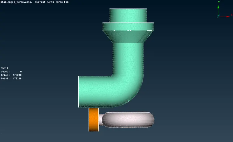
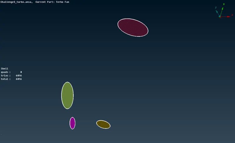
MESHING PROCEDURE:
Step 1: Provide the mesh length as given in the challenge in both perimeters and macros for each PIDs as mention below,
- Blade stage-1 = 1 mm
- Blade stage-2 = 1 mm
- Impeller = 2 mm
- Shaft rotor = 1 mm
- Turbo casing = 5 mm
- Compressor casing = 5 mm
- Inlet casing cover = 5 mm
Step 2: Give the mesh parameters such as,
* Mesh Length
* Type of Mesh
* Shape of Mesh - (Tria)
Step 3: Give the Quality of mesh in the Quality criteria tool tab.
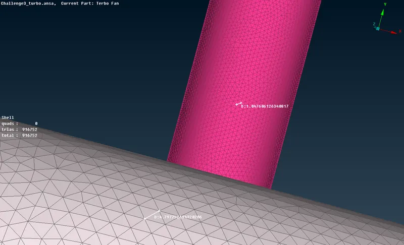
Step 4: After given the required values, to deploy the mesh, use the mesh generation tool. Use spot mesh to generate mesh over the selected faces (PIDs).
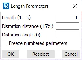
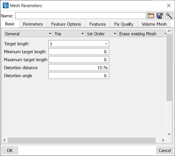
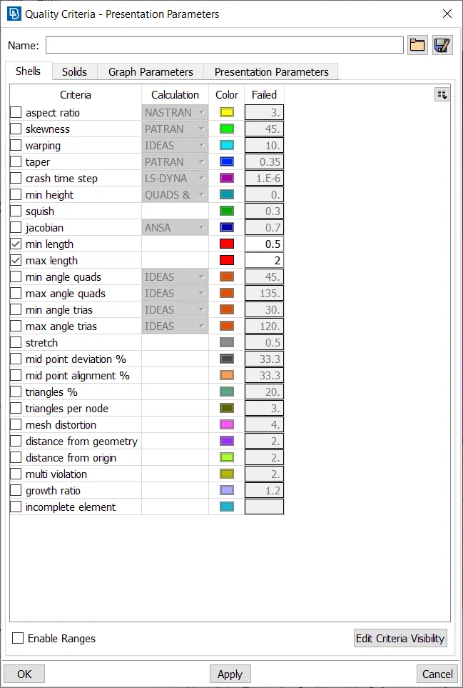
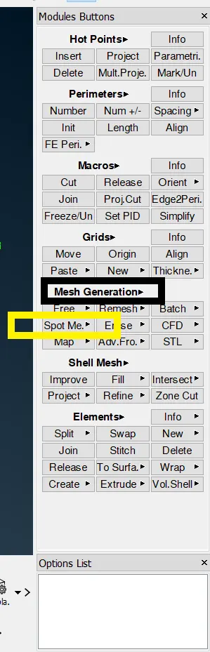
- Change the required values as given and mesh all the surfaces.
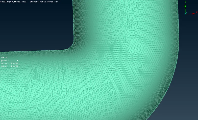
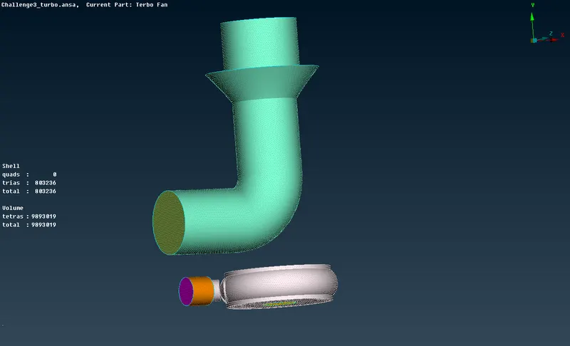
Volumetric Mesh:
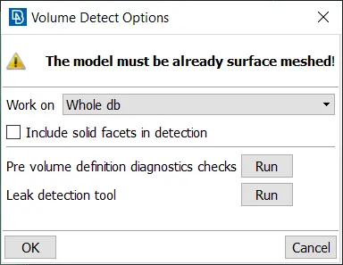
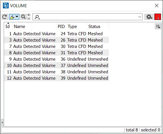
- Delete the unwanted volumes first.
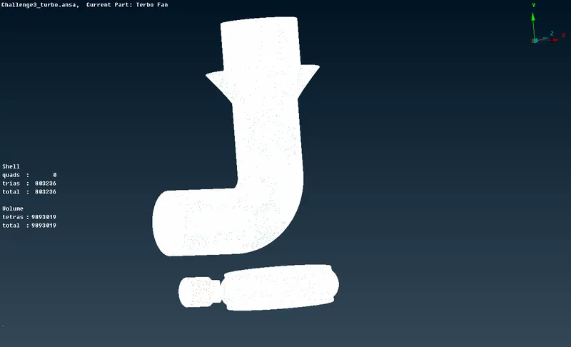
- Then Remesh the volumes individually as using the given mesh lengths.
Conclusions:
- Hence, the topology cleanup and mesh generation (surface and volume) are done on the given turbocharger assembly using ANSA as per the given specifications.
- Tria and tetra mesh elements were used to generate the surface and volumetric mesh respectively.
- A total of 916752 tria (surface mesh) and 9893019 tetras (volumetric mesh) elements were generated.