Week 3 Challenge
1. AIM: TO CREATE BEAM PROPERTIES FOR THE FIRST FLOOR AND MODEL BEAMS.
PROCEDURE:
- Open Tekla Structural designer (TSD) software.
- Open the existing project file that contains the previously modeled structure.
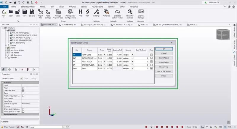
- Check construction levels and click open the first-floor level.
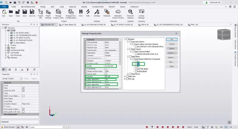
- Go to Home from the ribbon tab above and click on Manage properties. Create a new steel beam (horizontal) 'B2' with the following properties: Grade - Fe410WA, Section - MB300, Major alignment - Top, Minor alignment - Centre.
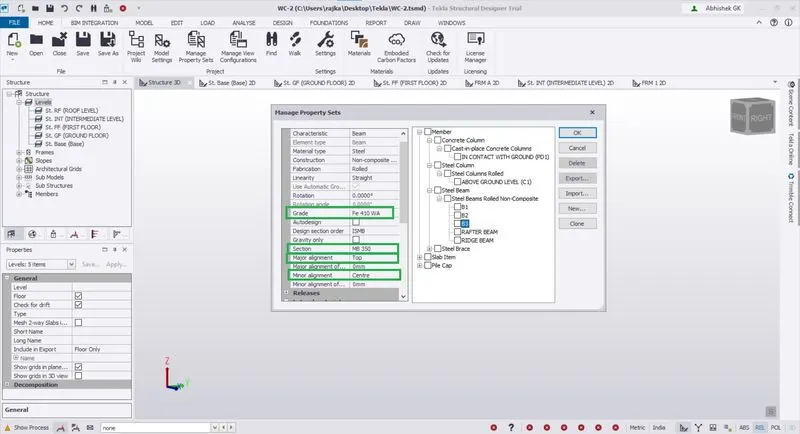
- Create another Steel beam (vertical) 'B3' with the following properties: Grade - Fe410WA, Section - MB350, Major alignment - Top, Minor alignment - Centre.
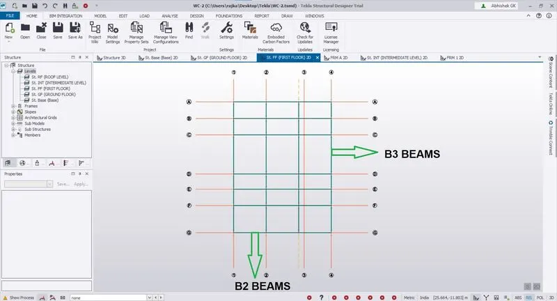
- Open the first-floor plan view and model beams (B2) from column to column horizontally.
- Perform the same operation to model beams (B3) from column to column vertically.
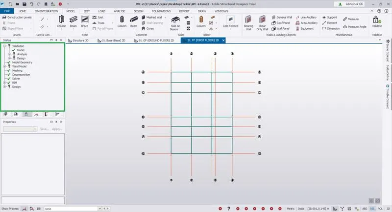
- Validate the model after these steps.
2. AIM: TO CREATE RAFTER BEAM ON THE SECOND FLOOR AS ROOF AND MOMENT FRAME ACTION IN ONE DIRECTION AND ADD BRACINGS AT LOCATIONS AS PER THE DESIGN INTENT
PROCEDURE:
RAFTERS
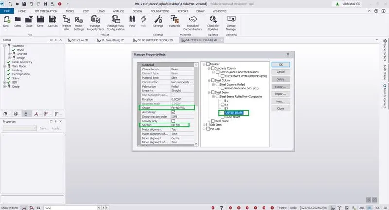
- In the same project file, go to manage properties and create a new member property for the Rafter beam. The member has to be created with the following properties: Grade - Fe410WA, Section - MB500.
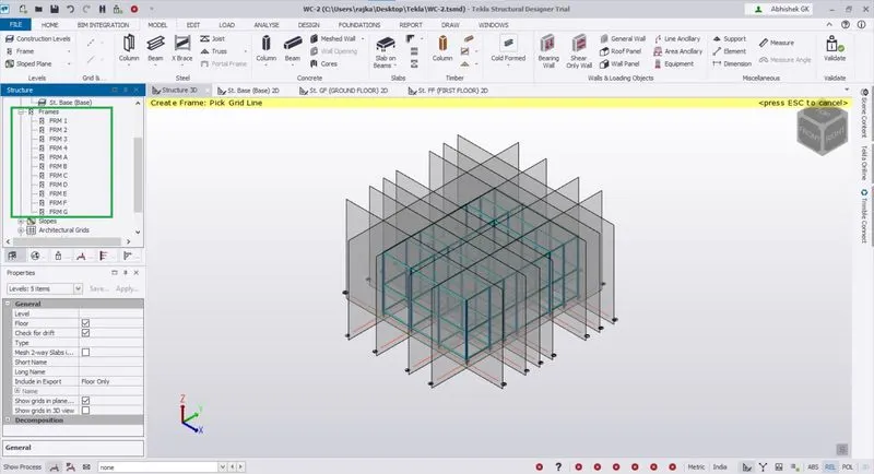
- Create frames by selecting the frame option from the ribbon tab on the top left corner. Create frames both horizontally and vertically by clicking on the respective grids 1-4 and A-G.
- Model rafters from one end of the column location to the center construction line intersection point and the same for the other end of the column.
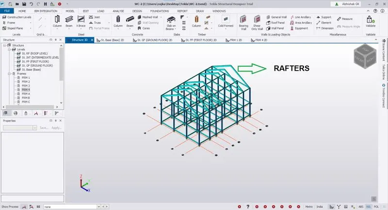
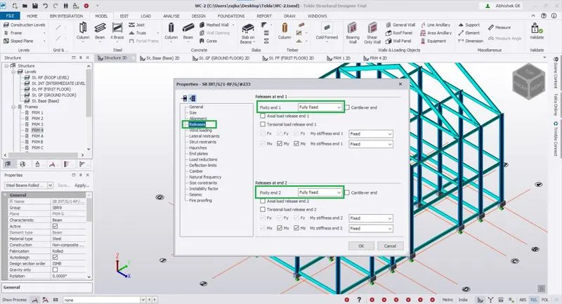
- After modeling the rafters at their locations, select each rafter and assign their fixity by double-clicking on them and select releases and give fully fixed for both fixity end 1 and fixity end 2. By doing this we give the moment action at the ends of the rafters.
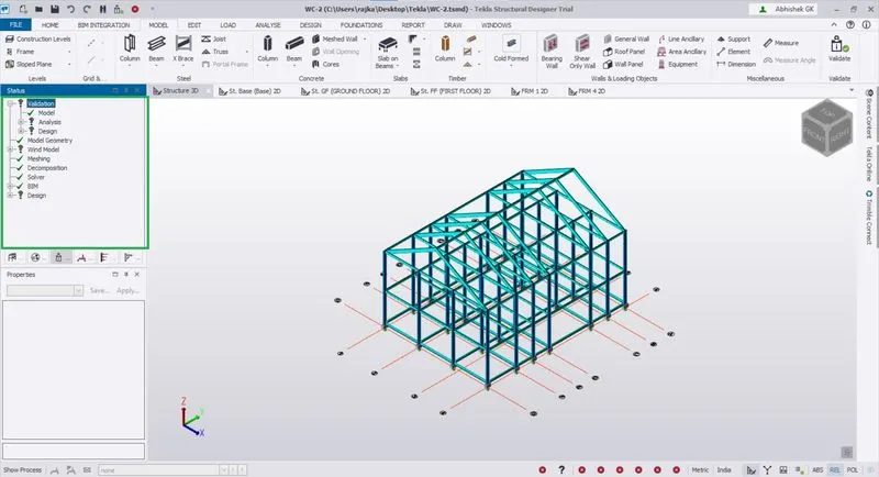
- Validate the model after these steps.
BRACING
- Goto manage property sets and create a new member property for bracing by selecting steel bracing.
- Braces have to be created with the following properties: Grade - Fe410WA, Section - Equal Angles ( 75 75 8 ), Connection - Bolted.
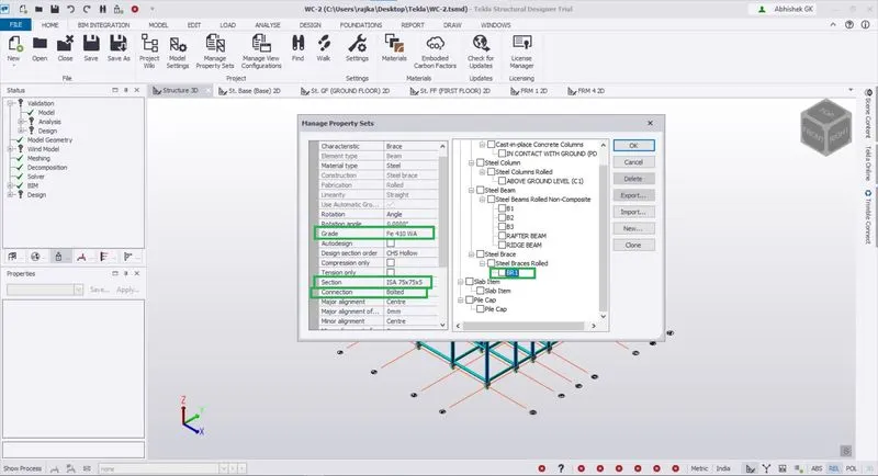
- Goto model and select 'X' BRACE from bracing option and select BR1 from property tab.
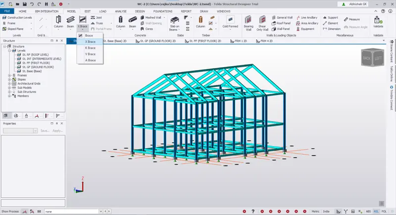
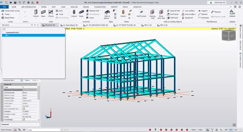
- Model braces on Grids 1 and 4 (sides of the structure) and begin modeling braces from the intersection points of columns and beams on the top and the next subsequent intersection points of columns and beams on the bottom.
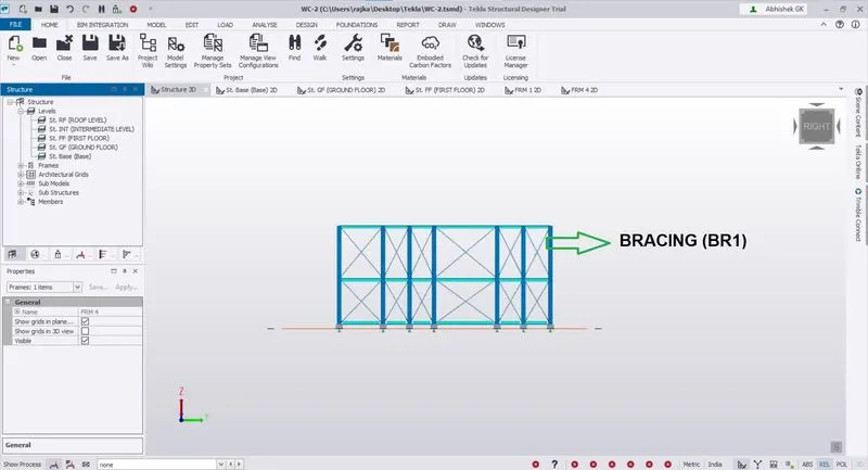
- Perform the same steps for modeling braces on all locations of the intersection of column and beams on Grids 1 and 4.
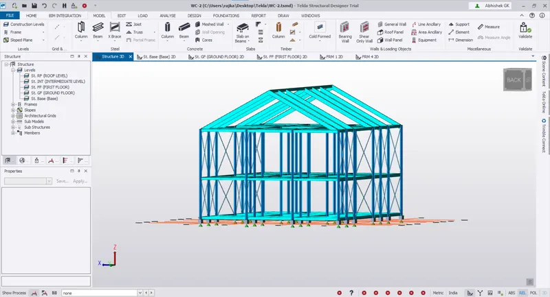
- Model braces on top of the roof with 'X' BRACE on the top of the structure. Model braces on all locations of the rafter to rafter points.
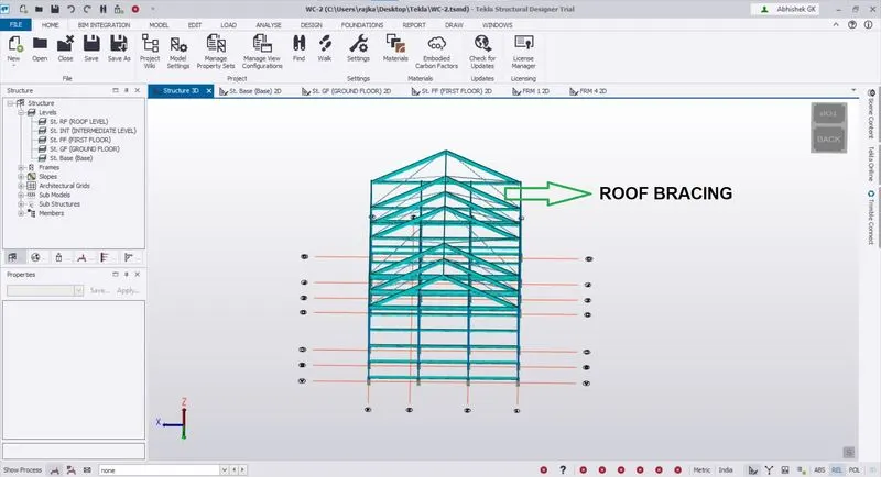
- Validate the model after modeling is complete.
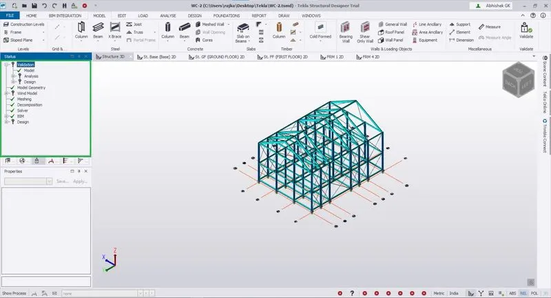
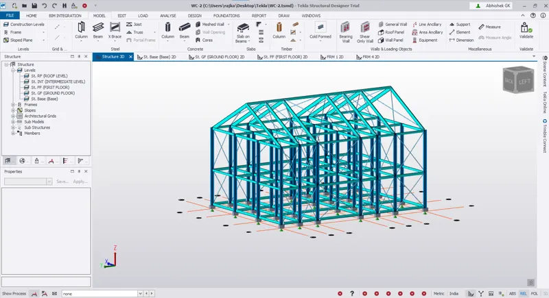
RESULT: A structure with beams, columns, pedestal members, rafters, ridge beams, and bracings is obtained. The structure is modeled up to the second floor.