Week 1 Challenge
1. A. PROJECT WORKSPACE
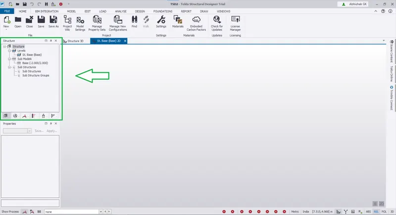
AIM: To access and usage of Project workspace in Tekla structural software.
PROCEDURE:
- Double click to open the TSD software.
- Select the 'new file' option from the Quick Access toolbar.
- The mini window that appears on the left side, below the ribbon tab is called the Project workspace.
- The project workspace window displays: various levels of the construction levels that are defined, the 3D view of the structure, models, sub-models, structures, and sub-structures of the project. It also shows loadings, design parameters, modeling parameters, groups, connections, and status of the project.
- To begin with modeling, any construction level from the project workspace can be selected and grids can be modeled.
1. B. SCENE CONTENT
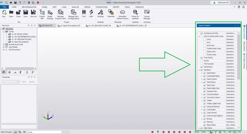
AIM: To demonstrate the use of scene content.
PROCEDURE:
- Scene content contains all the elements that are used in the design, modeling, and analysis of the project.
- These elements can be filtered to create a custom view.
- It allows the user to have a more customized view.
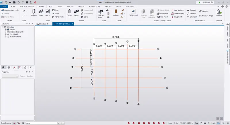
1. C. SCENE VIEW-1
Grids with dimensions.
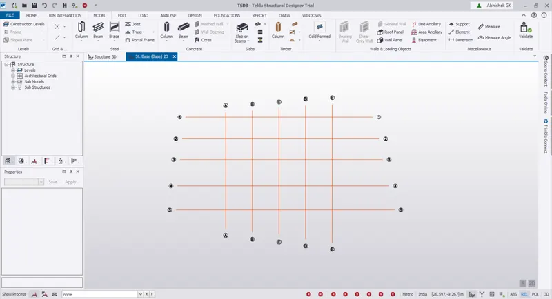
SCENE VIEW-2
Grids without dimensions.
1. D. LOADING DROP LIST
AIM: How to access the Loading list.
PROCEDURE:
- The loading list can be accessed from the bottom left side of the user interface window.
- It displays various loadings that are assigned to the members of the project.
1. E. PROPERTIES WINDOW
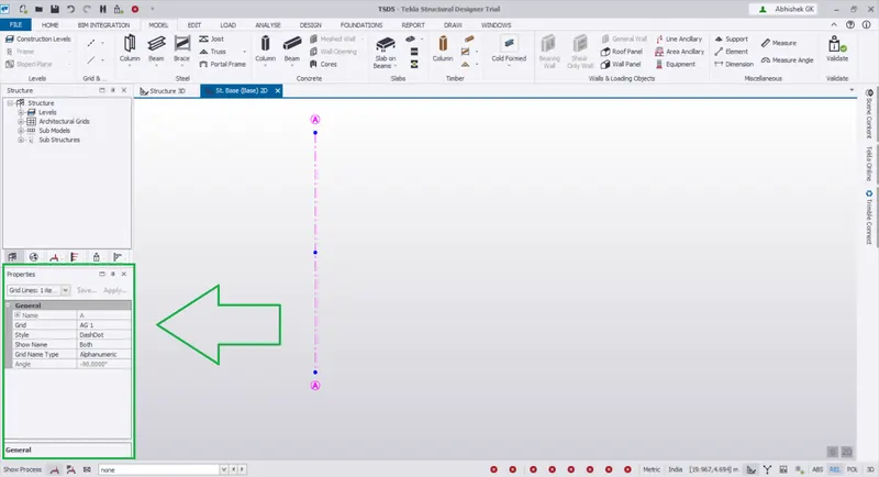
AIM: To access and usage of properties.
PROCEDURE:
- It is present below the project workspace window.
- It displays member properties and has a provision for editing the properties.
2. A project file containing the settings and parameters according to the given data.
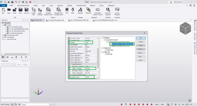
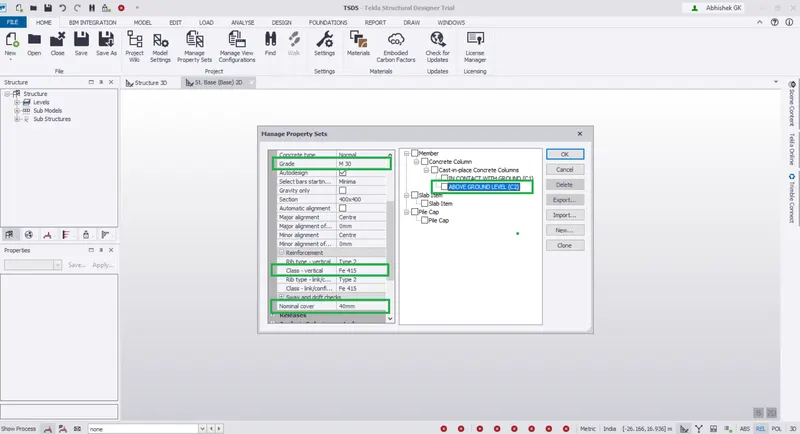
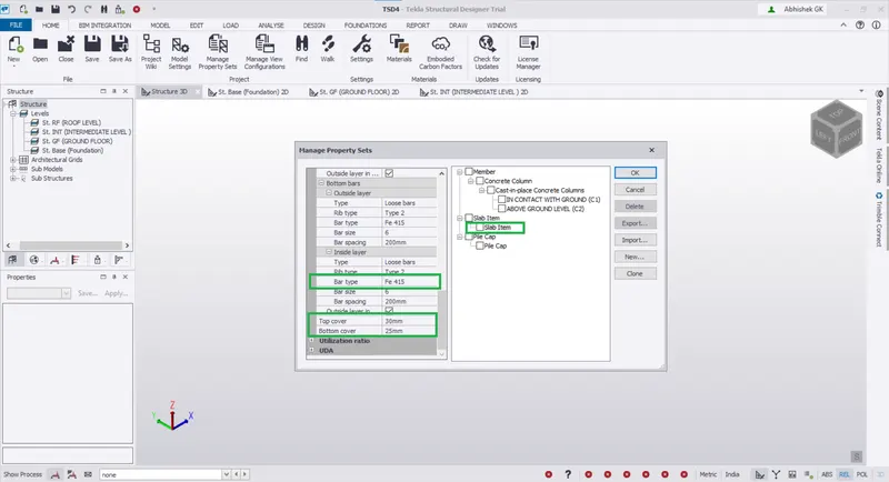

AIM: To create a project file with the given parameters.
PROCEDURE:
- Open a new file in TSD.
- Click on the manage property sets icon from the ribbon tab.
- Select 'new' and select members according to the given data.
- Assign the values for members according to the given data.
3. AIM: To study, summarize and create hand sketches of positions of columns and beams in attachments 1, 1.1 & 1.2.
Attachment-1:
- Shows ground floor plan view of the industrial steel building.
- It has a length of about 24.075 meters between horizontal grids A to G, and a width of about 18 meters between vertical grids 1 to 4.
- Column and beam positions are shown in the below image.
Attachment-1.1:
- Shows first-floor plan view.
- It has the same dimensions as the ground floor plan view.
- Columns are placed at every intersection point of grids and also at locations where the beam span length is more than the considerable length, thus avoiding unsupported length problems for beams.
- Beams span from column to column.
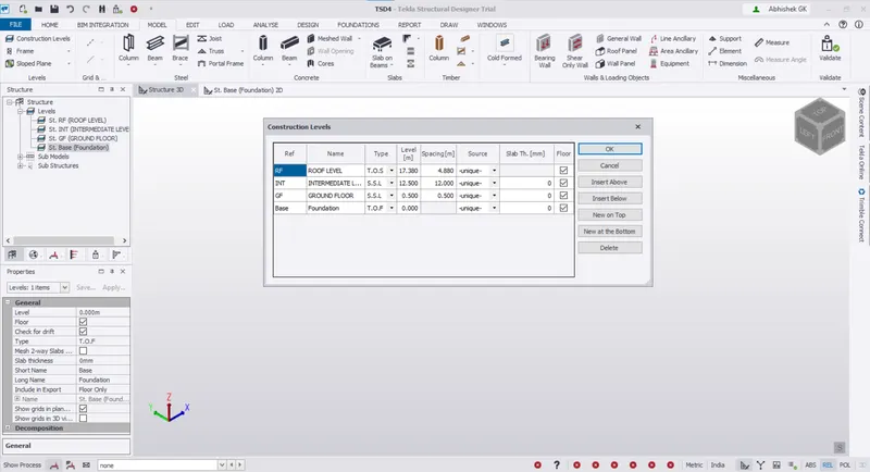
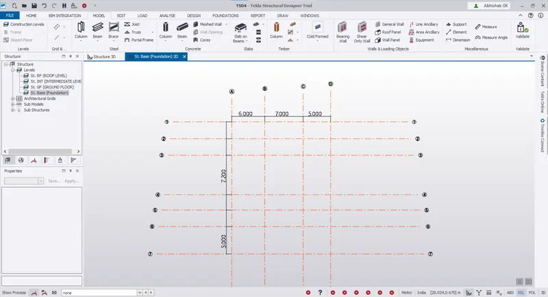
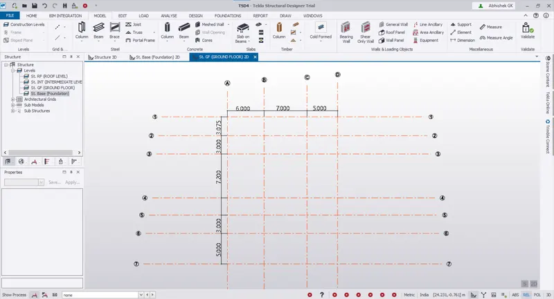
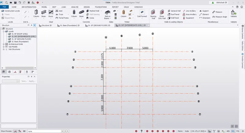
4. AIM: To model grid lines and construction levels according to attachments 1, 1.1 & 1.2.
PROCEDURE:
- Select a new project file from the quick access toolbar.
- Go-to construction levels on the top left corner of the window in the ribbon tab.
- Give the parameters according to the data in attachments.