Week 3 Challenge
ANSWER:
Aim:-
To write the brief and elaborate answers for the given essay questions and calculate the load conditions for the practical one.
Introduction:-
In this week 3 challenge we are going to give the answers of given essay questions for the first one is primary load cases, one way slab, unit weight of the structural steel and soil, define property sections and primary beams. The Second one was factors and prameters that influence the design pessure intencity of high rise building design and load transfer process of a reinforced cement concrete. The third one was differentiate the one way and two way slabs, secondary beams, primary load cases, assign the properties and supports to the model, create and assign the secondary beams. The final one practice was calculate the wind pressure, dead load and live load of the give hospital building in city centre and the locaion was darjeeling.
Procedure:-
1). Ans:-
1. Primary load cases to be considered for designing:
- Dead Load
- Live Load
- Wind Load
- Seismic Load
- Snow Load
2. One - way slab:
- One way slab is a slab, which is supported to a parallel wall or beams.
- The length to breadth ration is equal to or grater than two.
- It bends in the only one direction while tranfering the load to the two supports of wall or beams because of its geometry.
one way slab = (ly/lx) ≥ 2
3. Unit weight of steel and soil:
- Unit weight of structural steel = 7850 kg/m³
- Unit weight of soil = 1800 kg/m³.
4. Few section names:
- Circular
- Rectangular
- Tee section
- Trapezoidal
- General
- Tapered I
- Tapered tube
5. Primary beams:
- Primary beam is a horizontal flexural structural member which is directly connected to supporting structural member of column.
- It transfers loads to the column.
2). Ans:-
1. Factors and parameters that influence the design pressure intencity:
Pressure intensity, Pz = 0.6 Vz²
where, Pz = wind pressure
Vz = Design speed
Vz = Vb.k1.k2.k3
Vb = wind speed
K1 = Probability factor
K2 = Terrain, Height and structure size factor
K3 = Topography factor.
2. Load Tranfering process of RCC building:
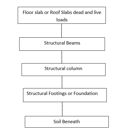
3). Ans:-
1. Differentiate the one way and two way slabs:
| One way slab | Two way slab |
| The ration of longer and shorter span was greater then or equal to two. | The ration of longer and shorter span was less then two |
| The slabs are supported by beams on the two opposite sides. |
In this slab the support will be carried on all directions or sides |
| The loads are carried in one direction. | The loads are carried on both longer and shorter direction. |
| The main reinforcement are provided in one direction. | The main reinforcement are provided in both direction. |
2. Secondary Beams:
- A horizontal beam does not directly connected to the column and its placed or supported by primary beams.
- secondary beams loads are tranfered to the primary beams.
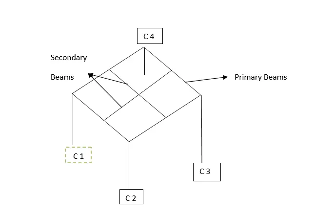
3. Primary Load Cases:
a. Indian standards for each load cases:
- Dead Load (IS 875:Part 1)
- Live Load (IS 875:Part 2)
- Wind Load (IS 875:Part 3)
- Snow Load (IS 875:Part 4)
- Earthquake Load (IS 1893:2016)
b. Parameters of each Load cases:
- Member Load
- Concentration Load
- Floor Load
- Plate Load
c. Load Cases:
Dead load: The dead load is defined as the constant load for the structure. The load caused by the weight of member was permanently attached by the structure. The load of the column, beam, wall, floor, roofs, door, windows, electrical fixtures and machanical fixers loads are comes under dead load.
Live Load: The live load of loads are fully or patialy vary from time to time on the structure. Live loads are not constant loads throghout of life span of the structure. It's may vary time to time according to the usage of the occupancy. The load may vary depends on the structure type like residential, commercial and industrial building.
Wind Load: Wind load is a force ofa structure that is arising from the impact of the wind pressure. This is an the important load case for the structure. This is suitable for the hilly or mountain areas we can expext the high spped of the wind can affect the structure. Mainly we calculate the wind load for the roofs.
Earthquake Load: Mainly we consider this type of load was high possibilites to occure the earth quake areas and according to the codel provisions, the seismic analysis carried out via any of the two methods, these are spectrum analysis and the time history analysis.
4. Steps to Assigning the Properties and supports to the model:
Assigning to Properties:
- After the creation of geometry we going to assign the properties.
- Choose the propertie tab on the ribbon menu bar.
- The properties-whole structure dialoge box will appeared.
- Next choose the define option on that dialogue box.
- After another one called property dialogue box will appeared.
- Then we select what type of stucture section we want and enter the sizes of the structure values manually.
- Then click add option.
- The sections and material type will be appeared on the first dialogue box.
- Choose that structure type and sect use cursor to assign option then select the structure to geometry creation.
- The properties will assigned has automatically.
Assigning to Supports:
- After assigning the properties and materials we goin to assign the support condtions.
- Select the supports tab on the ribbon menu bar.
- Appeared the dialogue box like supports - whole structure.
- Then select the create option and appeared on another dialogue box called create support.
- There was various support names like fixed, pinned, fixed but, enforced, enforced but, foundation, inclined and multilinear spring.
- Select the support which one you want then click add option and we can add multi number of supports.
- Then choose the supports from first dialogue box and chhoose use cursor to assign option.
- Finally select the beams to assign the supports automatically.
5. Create and assign secondary beams:
- The creation of secondary beams, firstly we have to create the structural frame and primary beams.
- Then take a add beam option and click on the top of primary beams.
- Suddenly the pop-up will appear like "do you want to add a node here" and click yes option.
- then the point window will be appear, choose the add mid point, add manual new point or add n portions which one you want then click "ok".
- The node will added automatically and the beam point also assigned.
- On the other end same procedure to be follwed and created the end node or end point of the secondary beam.
- Now the secondary beam will be created like the simply support condition.
- Select the specification tab on the ribben menu bar and choose it.
- choose the beam option on the specification windows and select the release member for the start and end beam and select the force and moment directions.
- Finally use cursor option to assign the specification of the secondary beams.
Practical:
given data:
- Building dimension = 20m x 30m x 20m height
- Building usage = Hospital
- LOcation = Darjeeling
1. Design wind speed:
- As per IS code 875 - Part III,
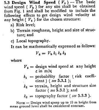
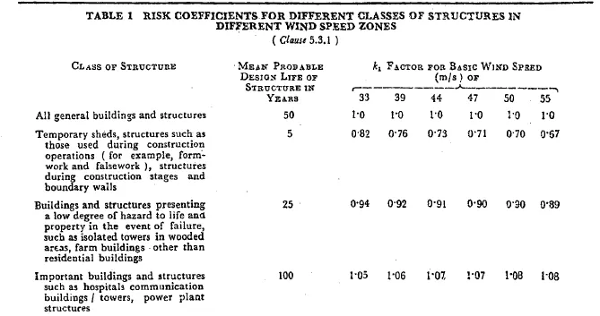
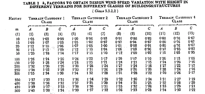
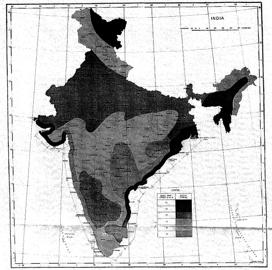
as per IS code,
- Vb = 47 m/s
- K1 = 1.07
- K2 = 0.8
- K3 = 1.0
so,
Vz = VbxK1xK2xK3
Vz = 47 x 1.07 x 0.8 x 1.0
Vz = 40.232 m/s.
2. Design wind pressure:
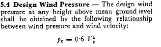
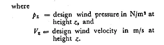
so,
Pz = 0.6 Vz²
Pz = 0.6 x (40.232)²
Pz = 971.16 N or 0.971 KN.
3. Dead load calculation:
As per IS code 875 - part I, The dead load is
Dead Load = volume of section x Unit weight
dead load of slab,
assume slab thicness as 150mm and area of slab is 20m x 30m
volume of section = 20 x 30 x 0.15 = 90 m³.
Unit weight = 25 N/m³
so, Dead load of slab = 90 x 25 = 2250 N or 2.25 KN.
4. Imposed Load or Live Load Calculation:
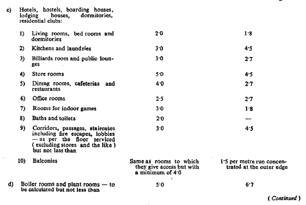
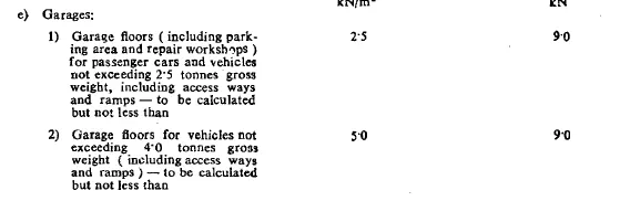
As per IS code 875 - Part II, the imposed load or live load on the floor UDL and concentrated load for different rooms are listed below. We taken it for an analyzing purpose.
Result:-
Written the brief and elloborate answers for the given essay questions and finally calculated the wind pressure, dead load and live of the given hospital building as per IS standards.
THE END