Project 1 _Creating an Architectural plan for the provided plot size and develop relevant basic structural drawings
ANSWER:
Aim:
To create an Architectural Plan for the Provided Plot size and develop relevent basic structural drawngs.
Introduction:
In this challenge has going to Develope the Residential building of architural and Structural drawings of the plot size of 60'x20' and the east facing orientation. There are many type of drawings included in structural and architectural drawings. They are,
1). Architectural Drawings:
- Floor Plan
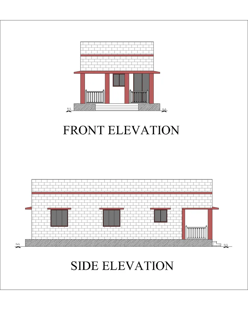
- Elevations
- Sections
2). Structural Drawings:
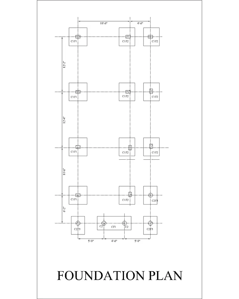
- Footing Plan
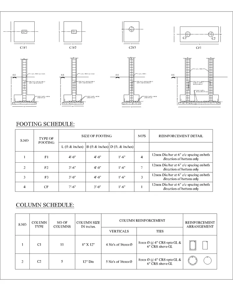
- Column
- Beam
Let's we can see about how to Develope the both Architectural and Structural Drawing of the given plot.
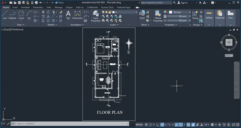
Commands Used:
- Limits & Units
- Line
- Rectangle, Circle, ellipse & Hatches
- Offset
- Copy & Move
- Fillet
- Trim
- Block & Block Edit
- Insert
- Desigh center
- Dimensions - linear, Alaighned, Dimstyle
- Text, Multitext and text edit
- Matchproperties
- Scale
Procedure:
- Create a new file for an architectural type of pricision is 0'-0" and the unit i inches.
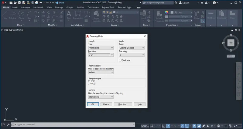
I). Architectural Drawings:
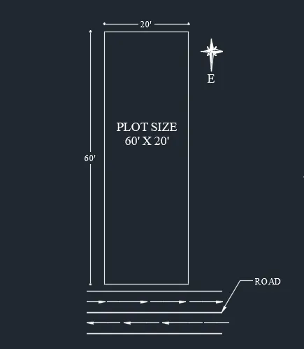
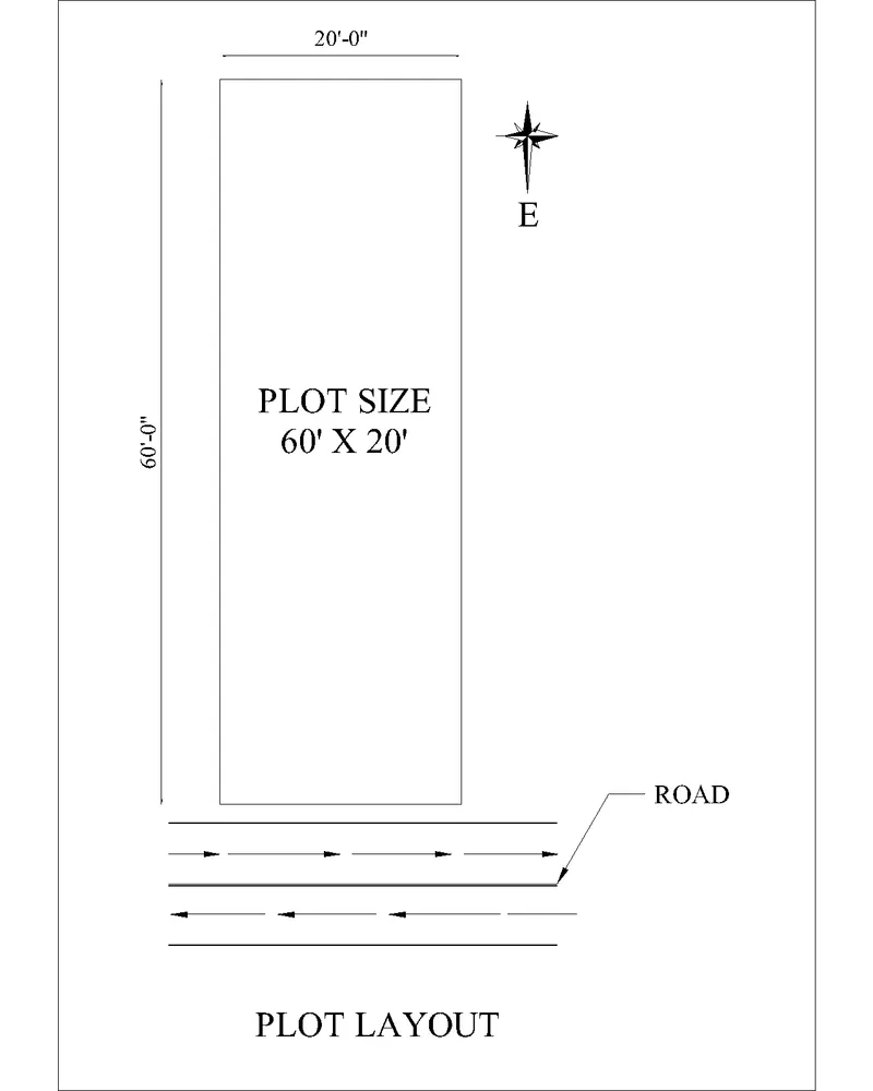
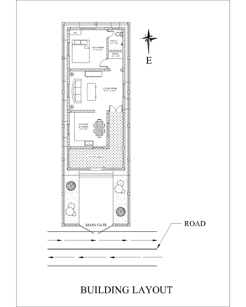
1. Plot: -
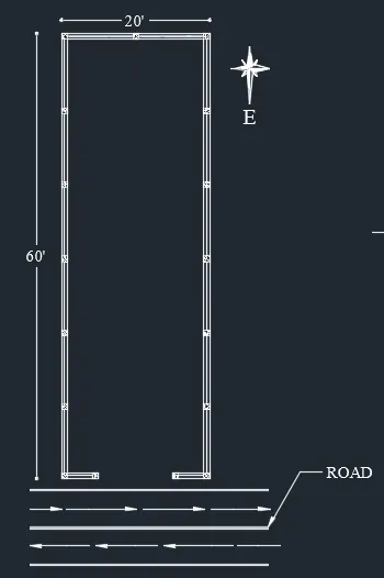
- Use rectanglur tool to draw a 60' x 20' of rectagle,
- Then select line tool to draw a Road,
- Then select Mtext to write the texts,
- and use annotation tool to mention the dimensions.
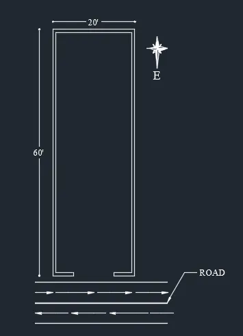
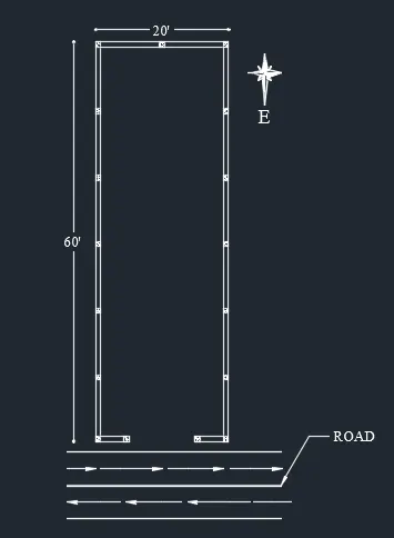
2. Compound wall Plan: -
- Select offset tool to offset plot line is 9" of inside the rectangle then trim the gate opening was 10 ft distance.
- Then Draw a rectagle of size 9"x9" then place at any one corner then hatch creation to use AR-CONC.
- Then Select the column and arrary it with path tool to the distance of 10 ft.
- Select line tool to draw a line column to column of each column to show the grill lines.
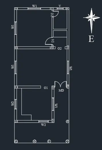
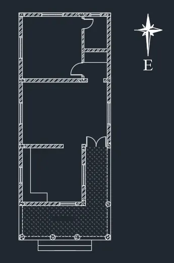
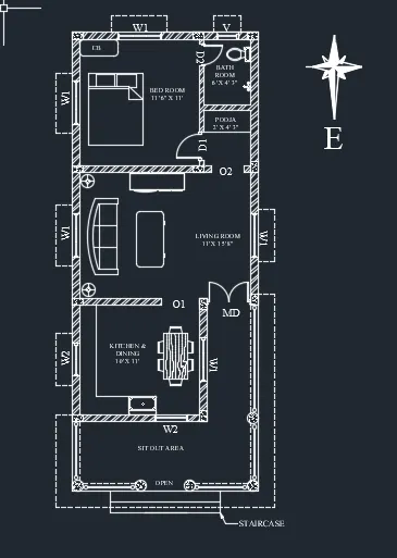
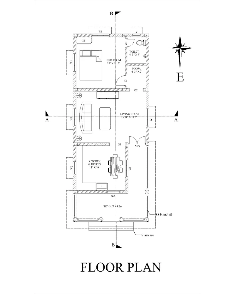
3. Floor plan: -
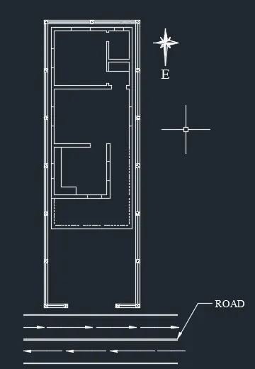
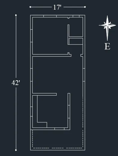
- Select REC tool to specify the first point at 1'-6" inside of x and y axis of upper left or right corner, Then draw a rectangle of size 17'x42',
- Then Select offset command to offset a lines on where the required distance like shown the figs.
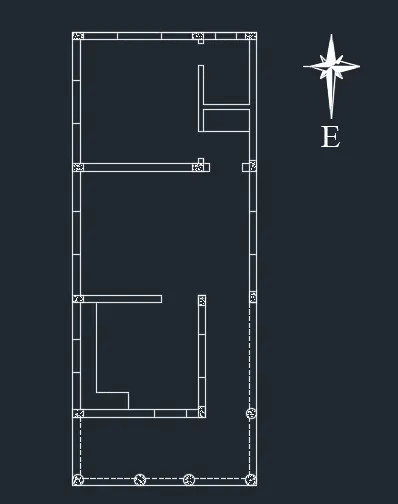
- Select REC tool to draw a column size 8"x12" then hatch it and copy to past like shown the fig.
- Select a Circle tool to make a circle radius of 6", Then Hatch it and copy to past like shown the fig.
- Then use line, circle, REC, offset and trim tool to create a block of windows, doors and ventilator of various sizes, then insert it with required places,
- Then use Hatch tool to hatch the wall and sit out areas,
- Type a command promte was DC (Design centre) to inset the furniture blocks dinning, sink, sofa, lamp light, desk, entertainment area, toilet and faucet.
- Use line tool to draw a staircase,
- Then change line layer type of dash line to draw a lintel level sunshide of sit out areas and windows & ventilator.
- Use Annotation tool to make Mtext and leaders on required places.
4. Sections: -
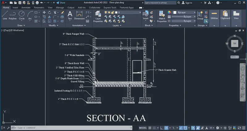
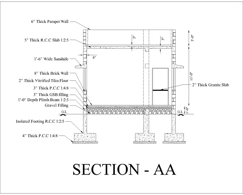
i). Section- AA:
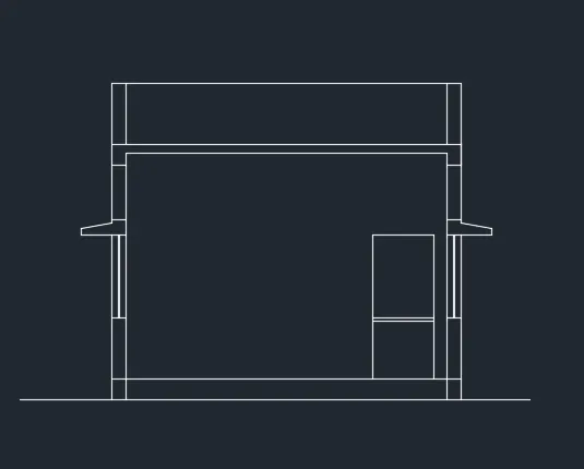
- Select line tool to Draw a line of ground level then select offset tool to offset it to FFL level then ofset to 7 ft height, then offset 5" thick of RCC slab, then offset to 3' height of parapet wall,
- Again select line tool to draw windows section and opening 2 to bedroom via pooja,
- Select line tool to draw the footings and PCC
- Select Hatch tool to hatch the different layers like PCC, Footing RCC, Gravel filling, GSB laying and tile layer, Granite slab, RCC slab, lintel and sunshides.
- Go to annotation menu bar select leader tool and specify the arrowhead for the different layers and define the layer types and the specifications and also use Text command to texting,
- Then use DIMLINEAR & DIMCONTINUE tool to specify the levels or heights,
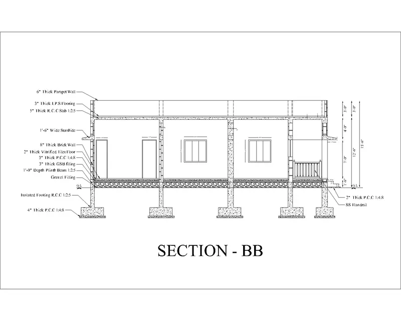
ii). Section - BB:
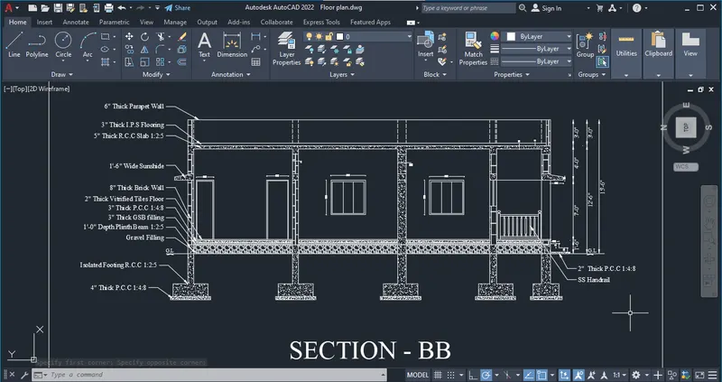
- Select a line tool to extend the lines for showing on section B to B lke shown the Floor plan,
- then draw a GL line on harizontally of extented line at anywhere,
- Then offset the lines for the same process of Section AA,
- Then trimming the Unwanted lines of were we required,
- Select hatch tool to hatching the same as Section AA,
- Go to annotation menu bar select leader tool and specify the arrowhead for the different layers and define the layer types and the specifications and also use Text command to texting,
- Then use DIMLINEAR & DIMCONTINUE tool to specify the levels or heights,
5. Elevations: -
i). Front Elevation:
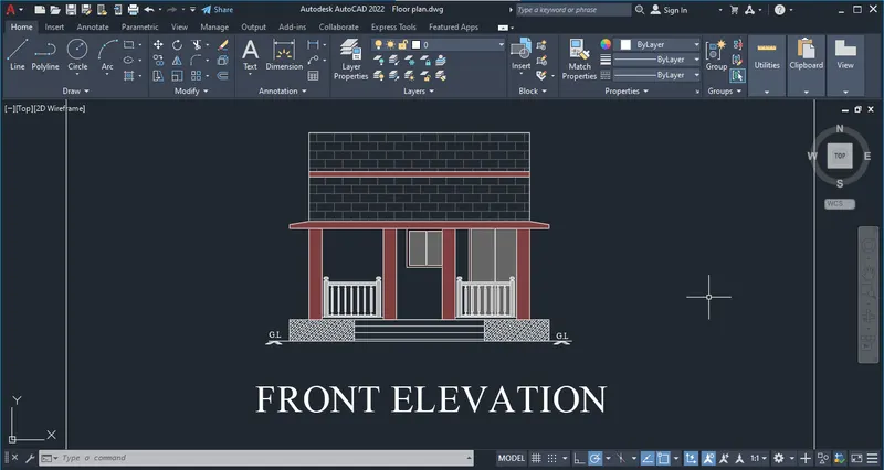
- Select line tool tool Extend the front facing lines of Floor plan,
- Then draw a GL line, Then offset the stair lines, lintel level, roof level and parapet wall height,
- Then, trim tool to triming the lines shown in fig,
- Select line tool to draw windows and doors,
- Then use line, REC, circle, ellipse, offset and array tool to make the ss handrail, same as copy to other side,
- hantch tool of solid to give column, slab, and sunshides of varient colour layer, and AR-B816 for above lintel level,
- Then Mtext to insert text.
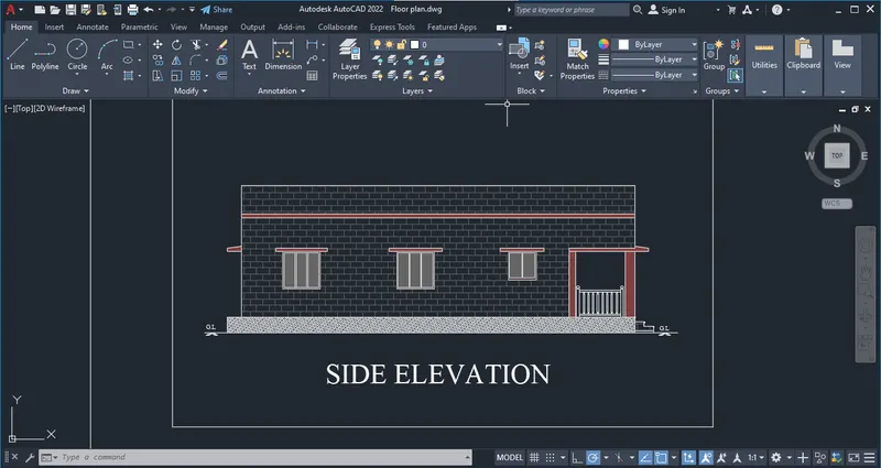
ii). Side Elevation:
- Select line tool the extent the lines for left side of the floor plan,
- Then draw a GL line, Then offset the stair lines, lintel level, roof level and parapet wall height,
- Then, trim tool to triming the lines shown in fig,
- Select line tool to draw a windows,
- Then use line, REC, circle, ellipse, offset and array tool to make the ss handrail,
- hantch tool of solid to give column, slab, and sunshides of varient colour layer, and AR-B816 for above lintel level,
- Then Mtext to insert the text
II). Structural Drawings:
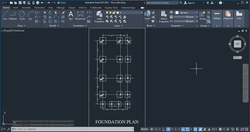
1. Foundation Plan: -
- Copy of floor plan then erase all objects except column,
- Then go to annotation bar select centerline tool to draw a cetreline of all intersecting columns,
- And extend the all lines,
- Then Select line or rec tool to draw a Footings Sizes on 4'x4', 4'x3'6", 4'x3' and 7'6"x3',
- Then place it when it's required,
- Select Dimlinear and dimcontinue command to show the distance between the centre lines,
- And select Mtext Tool to insert the texts
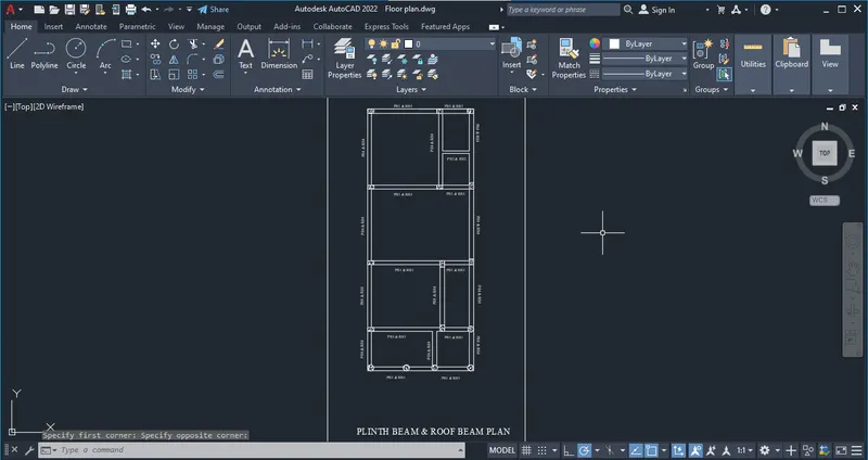
2. Beam Plan: -
- Copy of floor plan with erase all objects except wall and column,
- Then Extend command to extend all wall lines with intermediate lines
- Select Mtext tool to insert the texts of PB1 & PB2 and RB1 & RB2,
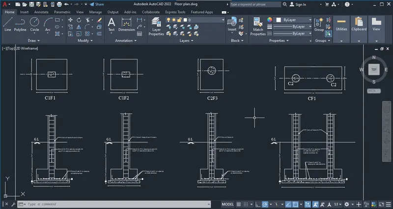
3. Footing & Column Sections:
- Copy of one no of C1F1, C1F2, C2F3 and C2CFC2,
- Then select line tool to extend the line to below
- The use line, offset, fillet, circle, trim, array to create the column sections and footing section of reinforcement arrangements,
- Hatch tool hatches the PCC and Bars,
- Select multileader tool to mention the specifications in detailed in number of bars and type of reonforcement and spacings,
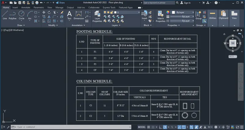
4. Footing & Column Schedule: -
- Create the footing schedule was go to annotation menu bar to selct Tables tool to insert the table on enter then columns value 7 and row was 6,
- Then scale to maximize the table
- Then enter the text what you want like shown in fig,
- The creation of Column Schedule was same as footing schedule in 7 no of column and 4 no of rows,
- Then type the texts, and column Section top view,
5. Beam Sections: -
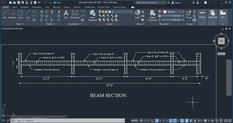
- Copy of floor plan to erase all objects except the left side of wall,
- Make the deth of 12" on any side,
- Then extend the column lines,
- offset tool to offset the line with 1" on top & bottom of beam, and sides of columns
- Use line command to draw 1 stirrup line then array it to 6" spacing of every stirrups on harizontally,
- Same as to make the column as well,
- Then the annotation of leader command to locate specifications of bar details,
- Then dimlinear and dimcontinue to Specify the distances
- Text command to type texts.
6. Beam Schedule: -
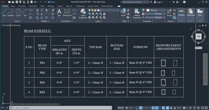
- Go to annotation menu bar to selct Tables tool to insert the table on enter then columns value of 8 and row value of 6,
- Then scale to maximize the table
- Then enter the text what you want like shown in fig,
- Draw a beam sections to paste here
- Mtext command to enter the texts like Beam Schedule.
Result: -
The creation of an Architectural Plan for the Provided Plot size and develop relevent basic structural drawngs are done and the plot results are followed,
Plot layout: -
Building Layout: -
Floor Plan:
Section - AA:
Section - BB:
Elevations:
Foundation Plan:
Beam Plan:
Columns & Footings Section & Scheduling:
Beam Section & Scheduling:
THE END