Week 3 Challenge
1.1 The primary load cases to be considered for design.
- Dead loads: These are the permanent loads that are always acting on the structure, such as the weight of the self-weight of the structure, any fixed equipment, and any permanent finishes.
- Live loads: These are the variable loads that can act on the structure, such as the weight of people, furniture, and movable equipment.
- Wind loads: These are the forces that are exerted on the structure by the wind.
- Seismic loads: These are the forces that are exerted on the structure by an earthquake.
- Snow loads: These are the forces that are exerted on the structure by the weight of snow.
- Ice loads: These are the forces that are exerted on the structure by the weight of ice.
- Other loads: This may include loads such as water pressure, soil pressure, and thermal loads.
1.2.
A one-way slab is a type of concrete slab that is supported on two parallel walls or beams and bends in one direction only. This is because the ratio of the longer span to the shorter span is greater than two. One-way slabs are typically used for floors and roofs in residential and commercial buildings.
One-way slabs are designed to withstand bending forces in only one direction. As a result, the main tension reinforcing bars run parallel (spaced uniformly) to the shorter span and are usually placed at the bottom of the slab. In the transverse direction (the longer direction), a minimum amount of reinforcement is provided to take care of the temperature and shrinkage effects in that direction. This steel reinforcement is called the distribution steel or secondary reinforcement.
1.3. The unit weight of structural steel is 78.5 kN/m⊃3;
The unit weight of soil varies depending on the type of soil and its moisture content. However, a typical value for the unit weight of soil is 18 kN/m⊃3;.
1.4.These are sections that are made of concrete. Concrete sections are typically used for beams, columns, slabs, and foundations. Some examples of concrete sections include:
- Rectangular beams
- T-beams
- L-beams
- Circular beams
- Square columns
- Rectangular columns
- Circular columns
- Slabs
- Footings
- Piles
1.5.Primary beams are the main beams in a structure that support the majority of the load. They are typically larger and stronger than secondary beams. Primary beams are often spaced wider apart than secondary beams, and they may be supported by columns or other primary beams.
Primary beams are essential for the structural integrity of a building. They must be able to withstand the weight of all the materials in the building, as well as any live loads, such as people, furniture, and equipment. Primary beams must also be able to withstand the forces of wind and earthquakes.
2.1. The following factors and parameters influence the design pressure intensity of a high-rise building:
- Basic wind speed: The basic wind speed is the average wind speed over a specific period of time, typically 3 seconds. It is determined by the location of the building and the terrain surrounding it.
- Height factor: The height factor accounts for the increase in wind speed with height.
- Topography factor: The topography factor accounts for the effects of hills, valleys, and other terrain features on the wind speed.
- Structure size: The structure size factor accounts for the fact that larger structures are more affected by wind than smaller structures.
- Wind directionality factor: The wind directionality factor accounts for the fact that the wind does not always blow from the same direction.
- Area averaging factor: The area averaging factor accounts for the fact that the wind pressure on a structure is not uniform over its entire surface.
- Importance factor: The importance factor accounts for the importance of the structure. More important structures, such as hospitals and schools, are designed to withstand higher wind loads.
2.2. The load transfer process of a reinforced concrete building is a complex process that involves the interaction of many different structural elements. However, the basic principle is that the loads are transferred from the roof and upper floors down to the foundation, where they are spread out and dissipated into the ground.
The following is a simplified overview of the load transfer process in a reinforced concrete building:
- Roof loads: The loads on the roof, such as snow, rain, and wind, are transferred to the roof beams and trusses.
- Roof beams and trusses: The roof beams and trusses transfer the loads to the exterior and interior columns.
- Exterior and interior columns: The exterior and interior columns transfer the loads to the foundation beams and footings.
- Foundation beams and footings: The foundation beams and footings spread the loads out into the ground.
3.1.
One-way slab:
- A one-way slab is a slab that is supported on two parallel walls or beams and bends in one direction only. This is because the ratio of the longer span to the shorter span is greater than two.
- One-way slabs are typically used for floors and roofs in residential and commercial buildings.
- One-way slabs are designed to withstand bending forces in only one direction. As a result, the main tension reinforcing bars run parallel (spaced uniformly) to the shorter span and are usually placed at the bottom of the slab. In the transverse direction (the longer direction), a minimum amount of reinforcement is provided to take care of the temperature and shrinkage effects in that direction. This steel reinforcement is called the distribution steel or secondary reinforcement.
- One-way slabs are relatively simple to design and construct, and they are a cost-effective way to span short distances. However, they are not as strong as two-way slabs, which are supported on four sides and bend in two directions.
Two-way slab:
- A two-way slab is a slab that is supported on four sides and bends in two directions. This is because the ratio of the longer span to the shorter span is less than two.
- Two-way slabs are typically used for floors and roofs in large buildings, such as office buildings, shopping malls, and warehouses.
- Two-way slabs are designed to withstand bending forces in both directions. As a result, the main tension reinforcing bars are placed in both directions, at the bottom of the slab.
- Two-way slabs are stronger and more rigid than one-way slabs, but they are also more complex to design and construct, and they are more expensive.
Here is a table that summarizes the key differences between one-way and two-way slabs:
| Characteristic | One-way slab | Two-way slab |
|---|---|---|
| Support conditions | Supported on two sides | Supported on four sides |
| Bending direction | Bends in one direction | Bends in two directions |
| Reinforcement | Main reinforcement in one direction | Main reinforcement in two directions |
| Strength and rigidity | Less strong and rigid | More strong and rigid |
| Design and construction | Simpler to design and construct | More complex to design and construct |
| Cost | Less expensive | More expensive |
3.2. Secondary beams are beams that are supported by primary beams. They are typically smaller and weaker than primary beams. Secondary beams are often spaced closer together than primary beams, and they may be used to support floors, ceilings, or roofs.
The secondary beam is supported by the two primary beams. The secondary beam is designed to withstand the weight of the floor and any live loads, such as people, furniture, and equipment.
Secondary beams are an important part of many structures. They help to distribute the load from the floors and roofs to the primary beams and columns. This helps to ensure that the structure is strong enough to withstand the expected loads.
3.3. The following are some examples of primary load cases:
- Dead load
- Live load
- Wind Load
- Seismic Load
- Snow Load
- Ice Load
3.3.a) The Indian Standards (IS) for each load case are as follows:
- Dead loads: IS 875 (Part 1) - 1987 - Code of practice for design loads (Other than earthquake) for buildings and structures - Part 1: Dead loads
- Live loads: IS 875 (Part 2) - 1987 - Code of practice for design loads (Other than earthquake) for buildings and structures - Part 2: Live loads
- Wind loads: IS 875 (Part 3) - 1987 - Code of practice for design loads (Other than earthquake) for buildings and structures - Part 3: Wind loads
- Seismic loads: IS 1893 (Part 1) - 2016 - Criteria for earthquake resistant design of structures - Part 1: General provisions and buildings
- Snow loads: IS 875 (Part 4) - 1987 - Code of practice for design loads (Other than earthquake) for buildings and structures - Part 4: Snow loads
- Ice loads: IS 875 (Part 5) - 1987 - Code of practice for design loads (Other than earthquake) for buildings and structures - Part 5: Special loads and load combinations.
3.3.b) The parameters of each load case will vary depending on the type of load case and the applicable design code. However, some common parameters include:
- Dead loads:
- Weight of the structural elements
- Weight of any fixed equipment or finishes
- Live loads:
- Occupancy type (e.g., residential, commercial, industrial)
- Intended use of the space (e.g., office, warehouse, retail)
- Any special loads that may be present (e.g., storage racks, heavy machinery)
- Wind loads:
- Basic wind speed
- Height factor
- Topography factor
- Structure size factor
- Wind directionality factor
- Area averaging factor
- Seismic loads:
- Zone factor
- Soil type
- Structure type
- Importance factor
- Snow loads:
- Ground snow load
- Exposure factor
- Thermal factor
- Ice loads:
- Ice load thickness
- Shape factor
- Wind speed
3.3.c) Here is a brief overview of each load case:
Dead loads are the permanent loads that are always acting on the structure, such as the weight of the structure itself, any fixed equipment, and any permanent finishes. Dead loads are typically the most predictable type of load, and they are relatively easy to calculate.
Live loads are the variable loads that can act on the structure, such as the weight of people, furniture, and movable equipment. Live loads are more difficult to predict than dead loads, and they can vary depending on the occupancy type and the intended use of the space.
Wind loads are the forces that are exerted on the structure by the wind. Wind loads can be significant, especially for tall and slender structures. The magnitude of wind loads depends on a number of factors, including the basic wind speed, the height of the structure, and the shape of the structure.
Seismic loads are the forces that are exerted on the structure by an earthquake. Seismic loads can be very large, and they can cause significant damage to structures that are not properly designed. The magnitude of seismic loads depends on a number of factors, including the location of the structure, the type of soil, and the type of structure.
Snow loads are the forces that are exerted on the structure by the weight of snow. Snow loads can be significant, especially in cold climates. The magnitude of snow loads depends on a number of factors, including the ground snow load, the exposure factor, and the thermal factor.
Ice loads are the forces that are exerted on the structure by the weight of ice. Ice loads can be significant, especially in cold climates. The magnitude of ice loads depends on a number of factors, including the ice load thickness, the shape factor, and the wind speed.
In addition to the above load cases, there are a number of other load cases that may need to be considered depending on the type of structure being designed. For example, a bridge may need to be analyzed for the loads imposed by traffic, and a crane may need to be analyzed for the loads imposed by lifting heavy objects.
4.To assign properties and support to a model using STAAD Pro, follow these steps:
Assigning Properties:
- Go to the Properties tab.
- Click the Define button.
- In the Define Properties dialog box, select the type of property that you want to assign.
- Enter the relevant properties for the selected property type.
- Click the Add button.
- Click the Close button.
- To assign the property to a member, select the member and then click the Assign button.
- In the Assign Properties dialog box, select the property that you want to assign and then click the Assign button.
- Click the Close button.
Assigning Support:
- Go to the Supports tab.
- Click the Define button.
- In the Define Supports dialog box, select the type of support that you want to assign.
- Enter the relevant properties for the selected support type.
- Click the Add button.
- Click the Close button.
- To assign the support to a node, select the node and then click the Assign button.
- In the Assign Supports dialog box, select the support that you want to assign and then click the Assign button.
- Click the Close button.
5.To create and assign secondary beams in STAAD Pro, follow these steps:
- Create the secondary beams using the Beam tool.
- Assign the appropriate material properties to the secondary beams using the Properties tab.
- Assign the appropriate support conditions to the secondary beams using the Supports tab.
- Connect the secondary beams to the primary beams using the Nodes tool.
Here is a more detailed explanation of each step:
1. Create the secondary beams using the Beam tool.**
To create a secondary beam, select the Beam tool from the toolbar and then click on the two nodes at the ends of the beam. STAAD Pro will create a beam between the two nodes.
2. Assign the appropriate material properties to the secondary beams using the Properties tab.**
To assign material properties to a secondary beam, select the beam and then go to the Properties tab. In the Properties tab, select the appropriate material type and then enter the relevant properties for the material.
3. Assign the appropriate support conditions to the secondary beams using the Supports tab.**
To assign support conditions to a secondary beam, select the beam and then go to the Supports tab. In the Supports tab, select the appropriate support conditions for the beam and then click the Assign button.
4. Connect the secondary beams to the primary beams using the Nodes tool.**
To connect a secondary beam to a primary beam, select the secondary beam and then go to the Nodes tool. In the Nodes tool, click on the node where the secondary beam connects to the primary beam. STAAD Pro will connect the two beams at the node.
Once you have completed these steps, the secondary beams will be created and assigned to your model. You can then proceed to analyze and design the structure.
PRACTICAL
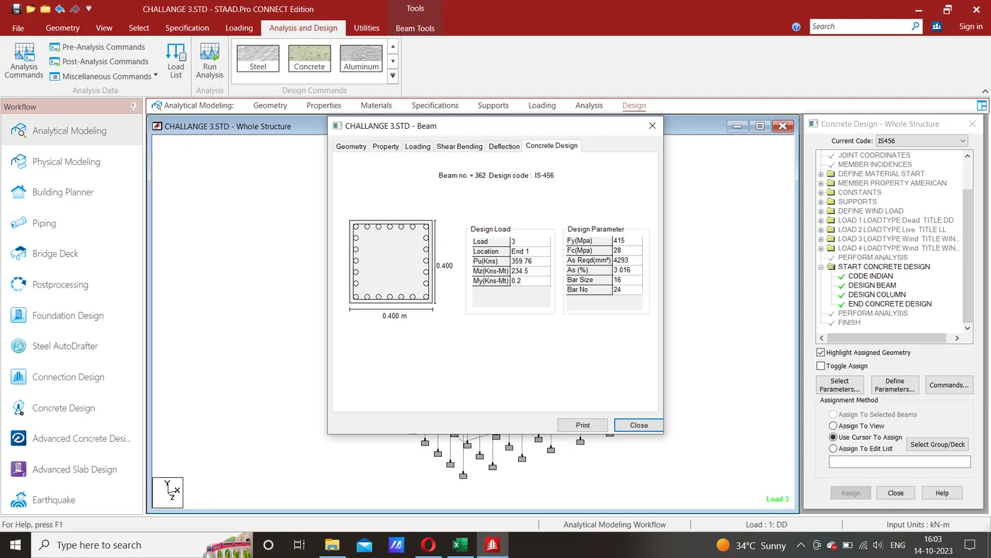
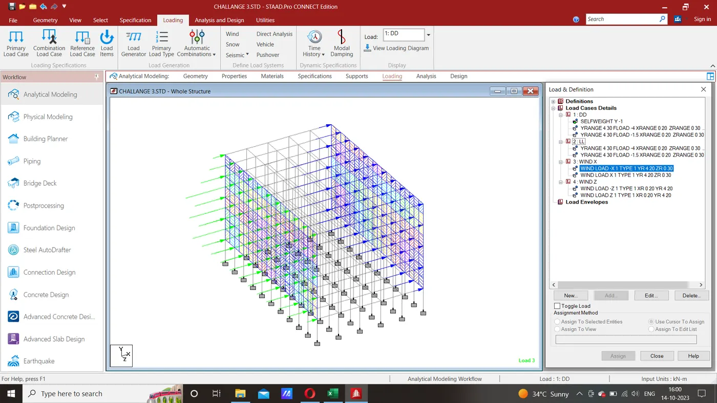
Given problem is analysed with the given dead, live and wind loads.
Screenshots, excel file and .std file is attached of the same given problem.