Challenge

Week 3 Challenge

a) The bridge design and construction, hydrology and geotechnical studies play a crucial role in determining the appropriate span length and type of bridge. These studies provide essential information about the water flow characteristics, soil properties, and geological conditions at the proposed bridge location. The Indian Road Congress (IRC) provides guidelines and standards for the design of bridges, including considerations related to hydrology and geotechnical aspects.

Hydrology and geotechnical studies are used in fixing span and selecting the type of bridge according to IRC standards, along with relevant clauses:

  1. Hydrology Studies: Hydrology studies involve analyzing the flow of water in the vicinity of the bridge site, including the determination of design discharge and flood levels. This information is crucial for designing the waterway opening and selecting the appropriate bridge type.

    Relevant IRC Clause: IRC 112 - "Code of Practice for Concrete Road Bridges" - Clause 203.1.3.2 (Design Discharge) and Clause 203.1.5.2 (Flood Levels)

    The hydrology study helps determine the design discharge (Q) based on the catchment area and rainfall characteristics. The flood levels are determined to ensure that the bridge can safely pass the anticipated floodwaters without causing damage.

  2. Geotechnical Studies: Geotechnical studies involve investigating the soil and geological conditions at the bridge site. This includes assessing soil strength, settlement, bearing capacity, and potential hazards such as landslides. The geotechnical information is used to determine the appropriate foundation type and span length for the bridge.

    Relevant IRC Clause: IRC 112 - Clause 305 (Subsurface Investigation)

    Geotechnical studies provide critical data for selecting the foundation type (e.g., shallow or deep foundations) and estimating the bearing capacity of the soil, which influences the span length and type of bridge that can be constructed safely.

  3. Preliminary and Detailed Studies: Preliminary studies involve initial assessments of hydrological and geotechnical conditions to make informed decisions about bridge location and type. Detailed studies provide more comprehensive data for the final bridge design.

    Relevant IRC Clause: IRC 112 - Clause 103 (Site Investigation)

    Preliminary studies guide the initial decisions on bridge type and location, while detailed studies provide the necessary data to refine the design and ensure its safety and durability.

  4. Zone of Influence: The zone of influence refers to the area surrounding the bridge site that could be affected by the bridge's construction and operation. This includes considerations for floodplain management, environmental impact, and potential changes in water flow patterns.

    Relevant IRC Clause: IRC 112 - Clause 201 (General)

    Assessing the zone of influence helps in understanding the potential impacts of the bridge on the surrounding environment, hydrology, and geotechnical conditions.

The scour depth at the pier and abutment locations of a bridge is a critical consideration in bridge design to ensure the stability of the structure. Scour depth is the depth to which the riverbed can erode due to water flow, which can undermine the foundations of the bridge. The design discharge and the silt factor are important parameters in estimating scour depth.

Given:

  • Silt Factor (F): 3
  • Design Discharge (Q): 1000 cumecs
  • Linear Waterway (L): 128 m

Scour depth (d) can be estimated using the following equation:

d=F×(Q/(g)1/2 x L)1/3

Where:

  • F is the silt factor
  • Q is the design discharge
  • g is the acceleration due to gravity (approximately 9.81 m/s²)
  • L is the linear waterway

adding in the given values:

d=3×(10009.81×128)1/3d=3×(9.81​×1281000​)1/3

Calculating the value within the parentheses:

10009.81×128≈2.3599.81​×1281000​≈2.359

Taking the cube root:

(10009.81×128)1/3≈1.277(9.81​×1281000​)1/3≈1.277

Finally, multiplying by the silt factor:

  • d ≈3×1.277≈3.831d≈3×1.277≈3.831

So, the estimated scour depth at the pier and abutment locations is approximately 3.831 meters. This is an approximation based on the given parameters and the simplified equation.

b) To prevent scour at a bridge with shallow foundations, various measures can be employed to protect the bridge piers and abutments from the erosive effects of water flow. These measures aim to dissipate energy, redirect flow, or stabilize the riverbed to minimize the potential for scour. Here are some commonly used scour prevention measures for bridges with shallow foundations:

  1. Riprap or Rock Armor: Placing a layer of large, durable rocks or stones around bridge piers and abutments can dissipate water energy and reduce erosive forces. The riprap acts as a buffer, absorbing the impact of flowing water and preventing scour.

  2. Gabions: As mentioned earlier, gabions are wire mesh containers filled with stones. They can be strategically placed around bridge foundations to redirect flow, slow down water velocity, and protect against scour.

  3. Toe Protection: Installing additional material at the base of the pier or abutment, such as concrete aprons or riprap, helps protect the foundation from erosion and minimizes the potential for scour.

  4. River Training Structures: Structures like groynes, spurs, or embankments can be constructed upstream of the bridge to influence flow patterns and sediment deposition, thereby reducing the erosive potential downstream.

  5. Grade Control Structures: These structures, such as weirs or stepped spillways, help control water elevation and velocity, preventing excessive erosion around the bridge.

  6. Pile Extensions or Collars: Extending the depth of the piers or adding protective collars around them enhances their resistance to scour.

  7. Armour Units or Mattresses: Concrete armour units or mattresses can be placed around bridge foundations to stabilize the riverbed and protect against scour.

  8. Vegetation Planting: Planting vegetation in the waterway can help slow down water velocity, trap sediment, and stabilize the riverbank and bed.

  9. Geotextile Fabric: Placing geotextile fabric along the riverbed in combination with other measures can promote sediment deposition and protect against scour.

  10. Regular Maintenance: Proper and routine maintenance of the bridge structure and scour protection measures is crucial to ensure their effectiveness over time.

The selection of scour prevention measures depends on factors such as site-specific conditions, hydraulic characteristics, local regulations, budget constraints, and the severity of the scour risk.
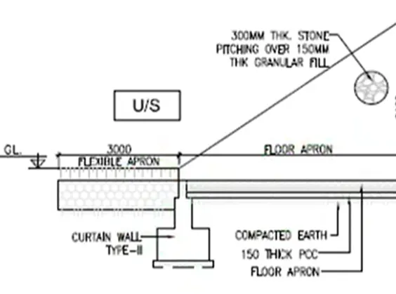
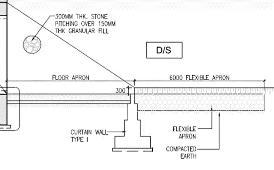
Measure to avoid the scouring as per IRC 13 are as follows:

Protection works – The rigid flooring should be provided under the bridge and it should extend for a distance at least 3m on the upstream and 5 m on the downstream side of the bridge. However, in case the splayed wing walls of the structure are likely to be longer, the flooring should extend up to the line connecting the end of the wing walls on either side of the bridge.

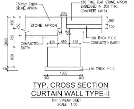
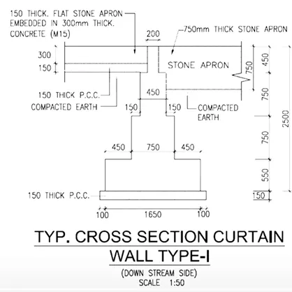
Flooring should consist of 150mm thick flat stone/brick on edge in cement mortar 1:3 laid over 300 mm thick cement concrete M15 grade laid over a layer of 150 mm thick cement concrete M10 grade. Joints at suitable spacing may be provided.

Curtain walls - The rigid flooring should be enclosed by curtain walls (tied to the wing walls) with a minimum depth below the floor level of 2 m on the upstream side and 2.5 m on the downstream side. The curtain wall should be in cement concrete M15 grade or brick/stone masonry in cement mortar 1:3. The rigid flooring should be continued over the top width of the curtain walls.

Flexible apron- Flexible apron 1 m thick comprising of loose stone boulders (weighing not less than 40 kg) should be provided beyond the curtain walls for a minimum distance of 3 m on the upstream side and 6 m on the downstream side. Where required size stones are not economically available, cement concrete blocks or stones in wire crates may be used in place of isolated stones.

c) Uplift can be defined as the upward pressure provide to the structure against the direction of gravity in such a way that has the potential to raise the structure from its initial position. It can be occurred due to an increase of the pore water pressure within the soil resulting summation of those pressure leading to uplifts in the structure.

IRC code, states that the upward pressure of water shall be taken as the full hydrostatic pressure applied over the entire area.

The structure must be designed properly to provide greater resistance against uplift forces in order to prevent risks due to water pressure. So, the uplift pressure must be taken into consideration during the design stage since rehabilitation and maintenance of the foundation cannot be carried out easily in the future.

Due to the uplift force structure tends to lose its stability and endangers to collapse. Due to the uplift force, the structure loses its anchorage with soil, which is maintained by the soil above the foundation, and tends differential positioning of foundation datum.

Prevention against uplift pressure

  • Dewatering of the site before construction plays an important role in it.
  • Increasing the self-weight of structure.
  • Provision of anchor bolts.
  • Increase the depth of footing in order to increase the weight of soil above the foundation
  • Provision of deep foundation in order to achieve hard strata.
  1. Force due to Uplift –

(i) Fu = γw x H (for 3 m height)

γw = Unit weight of water = 10 KN/m3

H = Height = in meters (m)

Fu = 10 x 3 = 30 kN/m2

(ii) Fu = γw x H (for 4 m height)

Fu = 10 x 4 = 40 kN/m2

(iii) Fu = γw x H (for 5 m height)

Fu = 10 x 5 = 50 kN/m2

Measure to prevent uplift are mentioned below as follows:

1. Toeing in the Foundation into the Surrounding Ground

When a substructure is built inside an open excavation or temporary cofferdam, the base slab or raft foundation can be extended outside the perimeter to increase resistance to uplift.

The weight of backfill material on the tied-in foundation increases the weight of the structure against uplift pressure. This method is not feasible where a diaphragm or secant pile wall is used as a permanent retaining structure.

2. Increase the Self-weight of the Structure

The self-weight of the building can be increased by increasing the size of the structural members. sometimes, the dead weight of the low-rise podium in a high-rise complex is increased by incorporating a rooftop garden with a thick soil fill.

3. Ground Anchors

Pre-stressed anchors can be used as a temporary measure to counteract uplift forces. The permanent application of ground anchors is limited by concerns about their long-term performance with respect to corrosion.

4. Piling Method

The piling method is the most effective method to resist Uplift pressure. Various types of piles are available to be used for countering uplift pressure based on soil condition and their necessity on site.

5. Gravity and Dead Load: Ensuring that the structure's own weight (gravity load) and any dead loads (permanent loads) are properly designed and distributed can help counteract uplift forces.

6. Adequate Foundations: Proper foundation design, including size, depth, and type (such as spread footings, piles, or caissons), can prevent uplift by ensuring that the structure's weight is securely transferred to the ground.

7. Anchoring Systems: For structures like buildings and towers, anchor systems such as anchor bolts, dowels, and tie rods can be used to connect the structure to its foundation and resist uplift forces.

8. Grouting and Pile Caps: In pile foundations, grouting the pile shafts and using reinforced pile caps can help distribute uplift forces and prevent separation between the piles and the structure.

9. Soil Improvement: Enhancing the properties of the soil through techniques like compaction, soil stabilization, or grouting can improve the soil's ability to resist uplift.

10. Counterweights: Adding counterweights to balance uplift forces can be effective, especially in situations where movable structures are involved, such as crane installations or bridge components.

11. Frictional Resistance: Utilizing friction between structural elements can resist uplift. Examples include friction piles or anchor plates with frictional surfaces.

12. Soil Nails or Tiebacks: In soil retention systems, soil nails or tiebacks can be used to anchor retaining walls and slopes, preventing soil movement and potential uplift.

13. Reinforcement: Incorporating reinforcement materials like steel bars or fibers in concrete or other materials can increase the overall strength and stability of a structure against uplift.

14. Wind Bracing: In structures like tall buildings, wind bracing systems can be employed to provide lateral stability and prevent uplift due to wind loads.

15. Seismic Design: Structures located in seismic zones should be designed to resist both lateral and uplift forces resulting from earthquakes.

16. Geogrids and Geotextiles: In geotechnical applications, geogrids and geotextiles can be used to stabilize soil, enhance load distribution, and prevent uplift.

17. Surcharging: Applying temporary surcharges to the soil can improve stability and enhance frictional resistance against uplift.

Each situation may require a combination of these measures based on the specific characteristics of the structure, foundation, soil conditions, and external loads.

Your portfolio, next

Ship work like this
in your own course.

Talk to a career counsellor

Free 20-minute call. We'll map the right course to where you want to work.

By submitting you agree to our Terms and Privacy Policy.