Week 3 Challenge
Q1.1- State the primary load cases to be considered for design.
A1.1- The dead load, Live load, Wind Load, seismic load, Temperature Load, Impact Load etc.
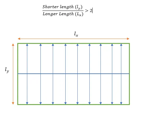
Q1.2- What is One – Way slab?
A1.2- One-way distribution is the ratio of longer span (lx) to Shorter span(ly) and lx/ly > 2.
Q1.3- What is the value of the unit weight of structural steel and soil?
A1.3- the unit weight of structural steel is 78.6 kN/m^3 and for soil is 18.0 kN/m^3.
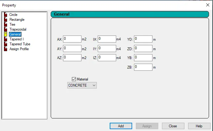
Q1.4- Name a few sections that can be defined using the Properties tab in STAAD Pro.
A1.4 There is various section in StAAD Pro.
Circular Section
Rectangular Section
T- Section
Trapezoidal Section
General
I- Section
Tube Section
Built up Section
Q1.5 Define Primary Beams.
A1.5 The primary beams are the beams that are directly connected with the column on both ends.The function of the primary beams is to transfer the load of the slab directly to the column that they are resting on.
Q.2.1 State the factors and parameters that influence the design pressure intensity of a high-rise building.
A.2.1 Various parameters for the design pressure intensity.
- Various and density of the wind.
- Height of the building from the ground.
- Geometry and aspect ratio of building.
- Topography of the surrounding ground surface.
- Angle projection of the wind.
- Dynamic load effect.
Q2.2. Mention the load transfer process of a Reinforced Concrete Building
A2.2 The sequence of the load transfer mechanism in the reinforced concrete building is Slab to beam, beam to column, column to the foundation, and foundation to earth.
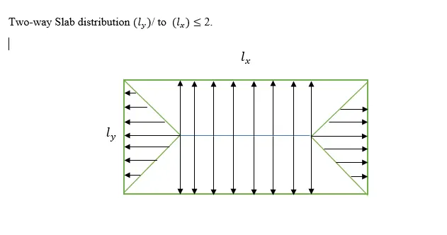
Q3.1 Differentiate One-Way and Two-way slabs. Elaborate on each slab type.
A3.1 One way is the ratio of shorter direction to longer direction.
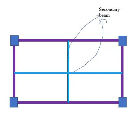
Q3.2 Explain the concept of secondary beams with a proper sketch.
A3.2 Name it self say the secondary beam means all the load is transferring on the wall or primary beam.
Q3.3 Mention the Primary load cases.
A3.3 The Primary Loads are
Dead Load as per IS 875 part 1
Live Load as per IS 875 part 2
Seismic Load as per IS 1893 part 1
Wind Load as per IS 875 part 3
Ice load
Temperature load
Accidental Load
snow load
fuild load
soil load
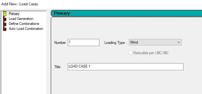
Q.4 Detail the steps involved in assigning Properties and cto a model using STAAD Pro sequentially.
A.4. Steps are followed to assign the properties of the model.
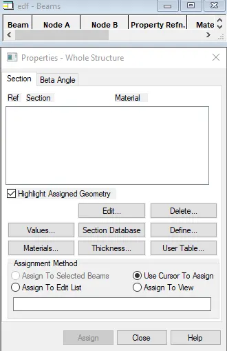
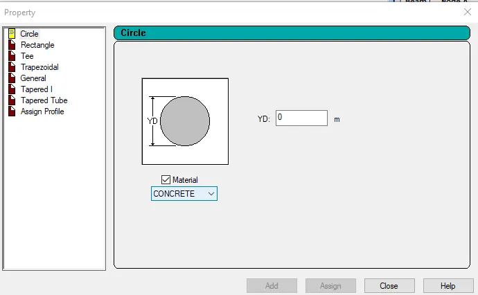
Open application> New file> Fill the detail of the beam model> geometry > circle properties> define > add> close.
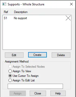
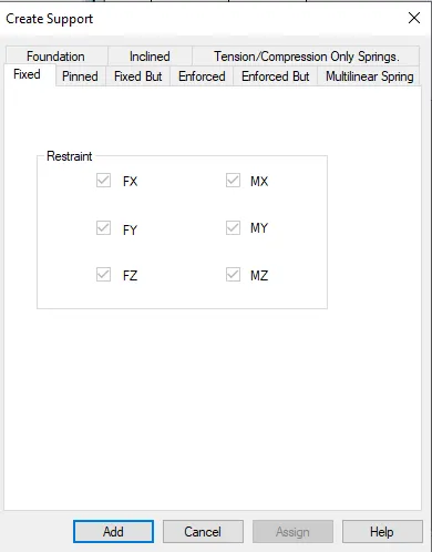
Goto support > create >Add> Assign
Q.5 Brief the steps to be followed to create and assign secondary beams in STAAD Pro
A.5 SECONDARY BEAMS are modeled first and property is assigned to BEAMS.
The steps that are involved in creating and assigning the secondary beams in STAAD Pro are discussed below:
- First, create a simple model by using the node in STAAD .pro
- Click on the create beam option and create a beam in the X and Z axis direction.
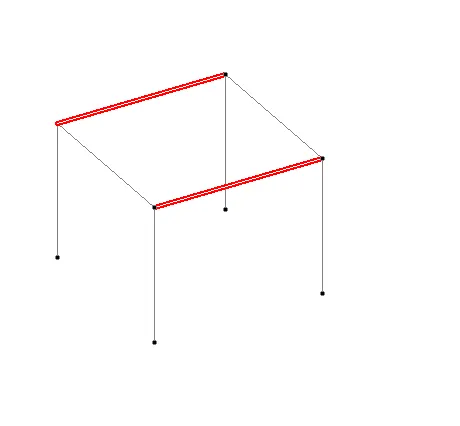
- Right Click on the primary beam in the section
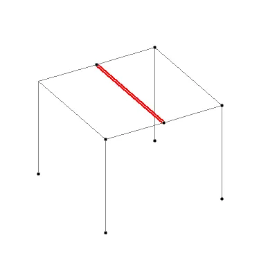
- Right-click and add Add node at the mid on the beam section a node will be added
- Click on the create beam to draw the beam along mid of the bay
Practical
5.1. Calculate the wind pressure for the given building
a. Building Dimension : 20m x 30m x 20m height RCC
b. Building usage: Hospital block in the city center
c. Location: Darjeeling
2. Calculate the Dead load and Live load for the above building with reference standards ( assume suitable sections
Procedure:
Gicev Data : Building dimensions:- 20m * 30m * 20m.
Buidling usage:- Hospital Block.
Location of the building:- Darjeeling.
STEP 1: Calculate Design Wind Speed:-
We know the formula to calculate the design wind speed, that is:
Vz = (Vb)x(K1)x (K2)x(K3)x (K4)
whereas, = Basic Wind Speed (m/se`
K1 = Risk Co-efficient
we can find the value of risk co-efficient, k1 from IS code 875:Part 3 2015, Table 1)
K2= Terrain Roughness and Height Factor
K3= Topography Factor.
We can find the value of the topography factor from IS code 875:Part 3 2015 clause no 6.3.3.
K4= Importance factor.
Given Data from the IS code:
Vb = 47 m/s
K1 = 1.07
K2 = 0.2
K3 = 1
K4 = 1
Vz = (Vb)x(K1)x (K2)x(K3)x (K4)
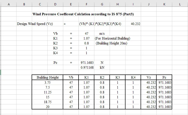
Vz = 47 x 1.07x 0.8 x 1x 1
Vz = 40.23 m/s
STEP 2: Wind pressure calculation
Pz = 0.6x (40.23)x (40.23)
Pz = 971.07 N
Pz = 0.971 kN
similarly, we can calculate the for different heights, the calculation for different heights has been done in the excel sheet so the excel sheet has been given below.
Q 5.2. Calculate the Dead load and Live load for the above building with reference to IS standards (Assume suitable sections).
A 5.2 Dead Load due to Slabs:
Thickness of slab size = (0.125m)
Unit of concrete = 25kN/m^3
Dead load of slab = unit weight of concrete x thickness of slab x per meter
Dead load of slab = 25 x 0.125 x 1 = 3.125 kN/m
Live load assume 2 KN/m for residential building
Total load = LL + DL = 2 + 121.5 +2126.5 +3.125 = 2253.125 kN
Self-weight of beam assumed for 4.5 m height for columns
For B (300mm x 450mm)
Dead load of beam size = (0.3 x 0.45 x 14 x 4.5) = 85.05 m^3
Unit of concrete = 25 kN/m^3
Dead load of beam = unit weight of concrete x size of the beam
Dead load of beam = 85.05 x 25 = 2126.25 kN
Superimposed Loads due to the Partition walls:
Assuming 150mm thickness of brickwork.
Height of brickwork = Floor height - depth of the beam
Height of the brickwork = 3.75 - 0.45 =3.30
Therefore, the dead due to partition wall = 3.3 x 0.15x 0.18 = 8.91kN/m
Live Load: We can calculate the live load of a given structure by using the IS 875:Part 2, which states different live loads values for different rooms, According to our building is the Hospital building, all the proposed live load values for the hospital building according to the IS 875:Part 3 has been listed below:
|
OCCUPANCY |
LIVE LOAD |
|
2.0 kN/m^2 |
|
3.0 k N/m^2 |
|
3.0 kN/m^2 |
|
2.0 k N/m^2 |
|
3.0 k N/m^2 |
|
2.5 k N/m^2 |
|
4.0 k N/m^2 |