Week 3 Challenge
- Aim: Usage of Hydrology and Geotechnical Studies while fixing of Span and type of Bridge as per IRC codes.
- Clauses for above one
- Calculation of Scour depth
- Measures to avoid Scouring at bridges
- Uplift meaning and it’s affects on foundation
- Calculations for the Uplift of U-Trough
Introduction:
Hydrology Studies and Scouring: Design discharge helps in deciding total length of bridge, depth of foundation and river training works required.
Geotechnical investigations are carried out to obtain necessary data related to engineering properties of soil for proposed structures’ foundations and the repair of distress earthworks for other types of structures caused by subsurface conditions.
How hydrology and geotechnical studies (preliminary and detail studies, zone of influence) are used in fixing span as per IRC standards and type of bridge. Mention the clauses applicable for the same.
The main objective is to study the basic design parameters of the project site along with engineering studies. The proposed tasks broadly involves mapping of the terrain features, site investigations such as topographical, traffic, geotechnical, hydrological etc. Selection of the best possible alternatives has been decide which has been taken up for detail working so as to provide a sound and appropriate engineering solution for the implementation of the project parameters. The objectives of the hydrological and hydraulic studies are set as follows.
SOME IMPORTANCE IRC CODES FOR BRIDGE HYDRAULICS
- IRC:SP:13-2004 Guidelines for design of Small bridges and culverts
- IRC:5-2015 Standard Specifications & Code of Practice for Road
- Bridges
- IRC-SP-54-2000 Project Preparation Manual for bridges
- IRC:SP:20-2002 Rural Roads Manual
- IRC-89-1997(New) guidelines design and construction of river training and control works for road bridges
HYDRAULIC DESIGN INVOLVE THE FOLLOWING STEPS
- Preliminary Investigation
- Data Collection
- Detailed Survey
- Site Visit(s)
- Hydrology Analysis, the Estimation of Flood Discharge
- Hydraulic Analysis, the Calculation of Flood Flow Patterns, Flood Levels and
Flow Velocities
- Bridge proposal, including assessment of options
- Frequency of submergence and duration of traffic obstruction
- Scour assessment
- Percentage (%) obstruction to Flow
|
PRELIMINARY INVESTIGATION |
||||
|
To review any previous investigations that have been carried out on this bridge, or on other nearby locations. |
|
|
|
|
|
eg. Type of Bridge |
||||
- High level bridge/submersible
- Superstructure/substructure/foundation
- Width
- Span arrangement and length
- Material classification
DATA COLLECTION
The data to be collected will include
- Stream flow data straight/meandering
- Observed high flood level
- General flood level/ordinary flood level
- Flow conditions (Quick discharge etc.)
Whenever this type of data is collected, it is important to review it carefully as they affect the design parameters.
- Cross sections ensure that the impact of afflux on flood level
- At least one defined cross section near by the proposed bridge site for hydraulic calculations.
- L-section of Nallah/River by taking levels 0.5 – 1 Km on U/S and D/S
- Bed material characteristics (sand/ silt/ boulders/weed growth)
- Nature of Nallah/River (straight, defined banks, flat river, pools, meandering)
- Characteristic of catchment area
- Shape (Fan / circular shape, Fern leaf-type or elongated)
- Agricultural land c. Forest area
- d. barren land etc
DETAILED SURVEY (IRC :SP:54-2000)
Survey is a critical component of any flood report for a bridge includesCross sections for reach both downstream and upstream of crossing
- 1. At least three cross sections on U/S and D/S spaced approximately 100-500 m apart
- 2. Cross section should be right angle to the flow and extend to higher than the highest expected flood level
- 3. The cross section reach sufficiently to allow the backwater dueto obstruction on downstream of the bridge. eg. Dam/Weir
- 4. Navigation Requirement
- 5. Whether the proposal is Rly affected (this many times dictates span arrangement)
- 6. Any irrigation project on U/S or D/S of the proposed bridge which would affect the proposal
Geotechnical investigations are carried out to obtain necessary data related to engineering properties of soil for proposed structures’ foundations and the repair of distress earthworks for other types of structures caused by subsurface conditions. The geotechnical investigation includes surface and subsurface exploration of a site. Subsurface exploration usually requires soil sampling and laboratory tests. In contrast, surface exploration can include geologic mapping, geophysical methods, and photogrammetry.
- Foundation soil and rock condition are primary information required for the economic design and construction of any structure.
- Required for Soundness, Safety and longevity of Structures
Geotechnical Investigation Objectives:
- The primary objective of the geotechnical investigation is to find out the nature of the soil and rock deposit.
- As per the foundation requirement, the depth and thickness of various soil types and rock strata can be obtained after geotechnical investigation.
- It helps to identify the location of the Ground Water Table(GWT).
- After geotechnical investigation, in-situ soil properties can be obtained by performing different Subsurface exploration and field tests (SPT, DCPT, SCPT, Vane Shear Tests, PMT etc.)
- The collection of soil and rock samples for determining engineering properties in the laboratory is under geotechnical investigation.
- Based on the available data after geotechnical investigation, the foundation type and depth can be decided.
- Geotechnical engineering assessment of foundations regarding their load-bearing capacity and settlement aspects shall be possible.
Geotechnical Investigation Stages:
Reconnaissance Stage:
- Soil and groundwater conditions
- Topography, drainage pattern, vegetation
- Condition of existing structures
- Suitability of site for the proposed project
- Types of soil and rock formations from geology
- Presence of natural resources
- Stream pattern, if any
- Seismic activity in the area
Planning of Geotechnical Investigation:
- Planning of geotechnical investigations includes the following stages.
- Location of geotechnical investigations.
- Numbers of geotechnical investigations (i.e.) Boreholes
- Depth of investigation.
Guidelines for Location, No’s and Depth of Borehole:
- IS: 1892-1979 – Code of practice for subsurface investigation for foundations
- IRC: 78-2014 – Standard specifications and code of practice for road bridges, section-Vii: Foundations and substructures (revised edition) – Appendix-2 under clause no-704.3
- Specification for road and bridge works, fifth revision, 2013 of MORTH by IRC -section 2400 (surface and subsurface investigation), section 2100 (open foundation), section 1100 (pile foundation) and section 1200 (well foundation)
General Locations of Investigation for Structure:
- Substructure: Pier and abutment locations for the following Structures (if any):
- Major bridges
- Minor bridges
- Grade separators/flyovers
- Vehicular underpasses (VUP)
- Overpass
- ROB (i.e. bridge over railway track)
- RUB (i.e. bridge under railway track)
- Pedestrian and cattle underpasses (PUP/CUP)
- Culverts (pipe or slab or box)
- Foot over bridges (FOB)
- Approach embankment locations for all the following structures (if any):
- Major and minor bridges
- Grade separators/flyovers/vehicular underpasses (VUP)
- ROB (i.e. bridge over railway track)
- RUB (i.e. bridge under railway track) / overpass
- Pedestrian and Cattle underpasses (PUP & CUP)
- Any running embankment locations having a height of 6.00 m and above
- Any building like administrative building and toll booths (if any)
- Pond and waterlogged area/ swampy locations (if any)
- Hill and valley slope, including landslide locations (if any)
For Shallow/Pile/Well Foundation in Soil or Rock:
- As per IS: 1892 (Reaffirmed 1997): At an interval of 50m centre to centre (Ref: Clause No. 2.3.2.1) shall be maintained.
- As per IRC: 78 – 2014 (Structure foundations in soil): Investigations shall cover the entire length of the bridge and also extend on either side for a distance about twice the depth below the bed of the last main foundation (Ref: Clause No. 3.2 of Appendix 2 of IRC:78-2014).
- As per IRC: 78 – 2014 (Structure foundations in rock): One drill hole per pier and abutment (Ref: Clause No. 3.2 of Appendix 2 of IRC:78-2014) should be made.
- As per MORTH technical specification, fifth revision, 2013:
- It should be at each pier and abutment location of the bridge (Ref: Clause No. 2402.1 of Section 2400).
- In the case of viaducts on either side of the bridge, bores shall be taken at each foundation of the viaduct spans(Ref: Clause No. 2402.1 of Section 2400).
- Suppose foundation strata variation appreciably affects the construction (especially in the case of bridge foundations resting on rock). In that case, it will be necessary to take additional bores in the transverse direction and establish the underlying strata’s complete profile (Ref: Clause No. 2402.2 of Section 2400).
Minimum depth of Geotechnical Investigation(Beyond Depth of Foundation):
For Shallow Foundation in Soil and rock:
- As per IS: 1892 (Reaffirmed 1997), Structure foundations in soil: Minimum depth of geotechnical investigation beyond the depth of the foundation should be one and half times the width of the foundation (Ref: Table 1 under clause no. 2.3.2.1).
- As per IS: 1892 (Reaffirmed 1997), structure foundations in rock:
- For massive and sound rock, the minimum depth of geotechnical investigation should be half of the effective width of the foundation.
- For moderately jointed and foliated rock, the depth of the geotechnical investigation will be the effective width of the foundation.
- For heavily jointed and weathered rock, the depth of the geotechnical investigation will be two times the effective width of the foundation.
- Minimum 3.00m geotechnical investigation depth should be considered inside rock mass (Ref: For buildings, clause no. 4.9.3.2 of IS:13063).
- As per IRC: 78 – 2014 (Structure foundations):
- The minimum depth of geotechnical investigation beyond the depth of the foundation should be one and half times the proposed width of the foundation.
- If any unsuitable/questionable foundation material is found beyond the depth of investigation stated above, then exploration shall be extended to a sufficient depth into a firm or stable soil or well into the sound rock (Ref: Clause No. 3.2, 6.2.2, 6.3.2 and 7.2.2 of Appendix-2 of IRC:78-2014)
- As per MORTH technical Specification, Fifth Revision, 2013:
- The geotechnical investigation depth for the foundation will be one and half times the proposed width of the foundation.
- Suppose any suitable foundation material of doubtful bearing capacity is found beyond the depth of investigation stated above. In that case, exploration of the depth of investigation shall be extended to 4 times the width of the foundation or till firm and stable soil or rock is achieved(Ref: Clause No. 2403.1 of Section 2400).
- If the rock is met, the drilling depth into rock having a ROD of more than 75% may be limited to 3 meters. (Ref: Clause No. 2403.1 of Section 2400)
For Pile/Well Foundation in Soil and rock:
- As per IS: 1892 (Reaffirmed 1997):The minimum depth of geotechnical investigation beyond the depth of the foundation should be one and half times the width of the foundation from the bearing level, i.e. toe of pile or bottom of well (Ref: Table 1 under clause no. 2.3.2.1).
- As per MORTH technical specification, fifth revision, 2013(for soil):Geotechnical investigation should be 1.5 times the estimated length of the pile in soil or 15m below the proposed founding Level (Ref: clause no. 1102.1 of section 1100 for “Pile Foundation” and clause no. 1202.3 of section 1200 for “Well Foundation”).
- As per MORTH technical specification, fifth revision, 2013(for rock) :
- Geotechnical investigation depth would be 15 times the diameter of the pile in weak/jointed rock but a minimum of 15m in such rock.
- Geotechnical investigation depth would be four times the diameter of the pile in hard rock but a minimum of 3m in such rock (Ref: Clause No. 1102.1 of Section 1100 for “Pile Foundation” and Clause No. 1202.3 of section 1200 for “Well Foundation”).
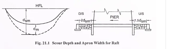
1b. what measures can be taken to avoid scour at bridge for shallow foundation. Also draw the section of measures on the downstream and the upstream side.
As per IRC SP 13 Article 20 To avoid scouring following measures can be followed,
- Provide protection works -The rigid flooring should be provided under the bridge and it should extend for a distance of at least 3 m on upstream side and 5 m on down stream side of the bridge. However, in case the splayed wing walls of the structure are likely to be longer, the flooring should extend upto the line connecting the end of wing walls on either side of the bridge. The top of flooring should be kept 300 mm below the lowest bed level. Flooring should consist of 1 50 mm thick flat stone/bricks on edge in cement mortar 1 :3 laid over 300 mm thick cement concrete Ml 5 grade laid over a layer of 1 50 mm thick cement concrete M10 grade. Joints at suitable spacings (say 20 m) may be provided.
- Providing flexible and rigid aprons - Flexible apron 1 m thick comprising of loose stone bouiders (weighing not less than 40 kg) should be provided beyond the curtain walls for a minimum distance of 3 m on upstream side and 6 m on downstream side. Where required size stones are not economically available, cement concrete blocks or stones in wire crates may be used in place of isolated stones. In this context, relevant provision in IRC:89-1997 is also referred.20. 1 .2.5. Wherever scour is restricted by provision of flooring/flexible apron, the work offlooring/apron etc., should be simultaneously completed alongwith the work on foundations so that the foundation work completed is not endangered.
- Provide Cut off walls / curtain walls - The rigid flooring should be enclosed by curtain walls (tied to the wing walls) with a minimum depth below floor level of 2 m on upstream side and 2.5 m on downstream side. The curtain wall should be in cement concrete Ml 5 grade or brick/stone masonry in cement mortar 1:3. The rigid flooring should be continued over the top width of curtain walls. In this context,
relevant provision in "Guidelines for design and construction ofriver training and control works for road bridges", IRC: 89-1997 is also referred. - Providing adequate depth of foundation
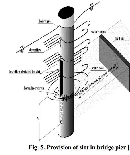
Reduction of scouring is possible by different approaches, using different countermeasures. Ripraps and geo bags reduce the scouring up to 40-50%. Collars reduces the scouring at great extent if it is placed at or below river bedlevel. Rectangular collar reduces the scouring to 79% Collar having dimension 1.5 to 2 times the pier dimension reduces the scouring in the range 55% to 96% Slot is most efficient if the angle between slot and the current is in the range 20°. If the slotwidth is one fourth of the pier diameter the scour reduction is 20% and if the width is one half of the pier diameter, the scour reduction is 30%.If the slot is placed at river bedlevel,it reduces the scouring to 60-88%. Scouring reduction of 100% is possible by using both collar and slot incombination.
1.c What is uplift and how it can affect the foundation. (loss of contact)
Uplift pressure, which is also known as hydrostatic uplift, is an upward pressure applied to a structure that has the potential to raise it relative to its surroundings. It is the condition of greater pore water pressure than the overburden pressure of the structure.
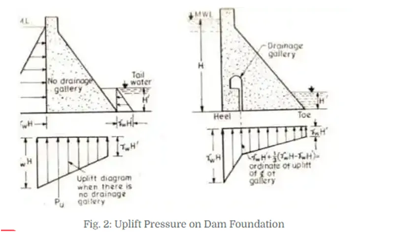
Consequences of Uplift Pressure
- It reduces the effective weight of the structure.
- Endanger stability of the structure
Q.Calculate the uplift in U trough of below section with height 3,4,5 meters. with water level on top of ramp wall leve
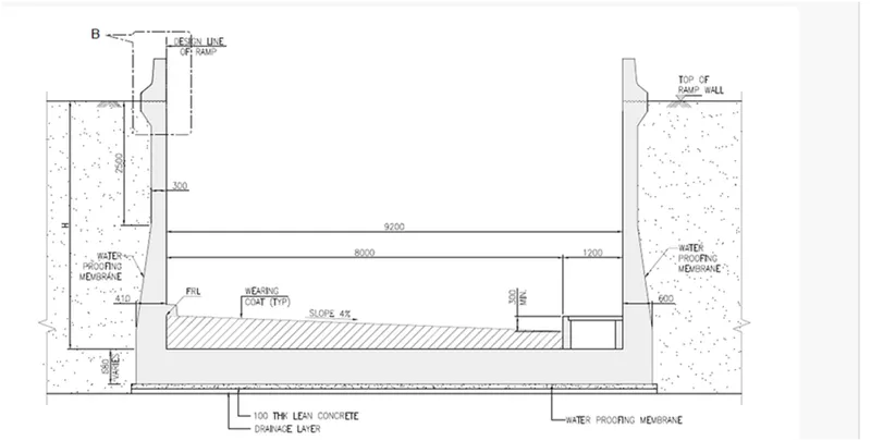
Self Weight of U-trough for 3m height:
=(9.2*0.68)+((0.6+4)/2*3)/1m lenth *25 Kn/m3 =193.9 kn per meter length
Up-lift pressure of U-trough for 3m height:
=(3+.68)*(9.2+1)/1m length *10 kn/m3 = 375.36 kn per meter length
Self Weight of U-trough for 4m height:
=(9.2*0.68)+((0.6+4)/2*4)/1m lenth *25 Kn/m3 = 206.4kn per meter length
Up-lift pressure of U-trough for 3m height:
=(4+.68)*(9.2+1)/1m length *10 kn/m3 = 477.36kn per meter length
Self Weight of U-trough for 5m height:
=(9.2*0.68)+((0.6+4)/2*5)/1m lenth *25 Kn/m3 = 218.9 kn per meter length
Up-lift pressure of U-trough for 3m height:
=(5+.68)*(9.2+1)/1m length *10 kn/m3 = 579.36 kn per meter length
Q. What are different measures that can be taken to avoid uplift.
Strategies for Prevention of Uplift Pressure
Dewatering procedure may help to control the water away from construction site, but it cannot keep the dewatering the whole life span of the construction as it is not an economical move. There are number of methods by which the influence of uplift pressure is avoided.
1. Toeing in the Foundation into the Surrounding Ground
When a substructure is built inside an open excavation or temporary cofferdam, the base slab or raft foundation can be extended outside perimeter to increase resistance to uplift.
The weight of backfill material on the tied-in foundation increase the weight of the structure against uplift pressure. This method is not feasible where a diaphragm or secant pile wall is used as a permanent retaining structure.
2. Increase Self-weight of the Structure
The self-weight of the building can be increased by increasing the size of structural members. sometime, the dead weight of the low-rise podium in a high-rise complex is increased by incorporating a rooftop garden with a thick soil fill.
3. Ground Anchors
Pre-stressed anchors can be used as a temporary measure to counteract uplift forces. Permanent application of ground anchors is limited by concerns about their long-term performance with respect to corrosion.
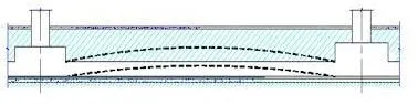
Fig. 3: Deflected Shape Due to Uplift Pressure in the Absence of Anchors
4. Piling Method
The piling method is the most effective method to resist Uplift pressure. Various types of piles are available to be used for countering uplift pressure based on soil condition and their necessity on site.
For instance, end bearing pile, friction pile, un-reamed pile, sheet pile, tension pile, and compaction pile. Table 1 presents different types of piles used to contain uplift pressure based on soil conditions.
Table 1 Types of Piles Chosen Based on Soil Conditions to Withstand Uplift Pressure
|
Types of Pile |
Suitable Types of Soil |
|
End bearing pile |
Used when bedrock or rocklike material is present at a site within a reasonable depth. Piles are extended to the rock surface. The ultimate bearing capacity of the pile based on the underlying material. |
|
Friction pile |
It is used in cohesionless soil in which end bearing pile would be very long and uneconomical. The load on pile is resisted mainly by skin/friction resistance along the side of the pile. Capacity of the pile is a function of the shaft area in contact with the soil. Friction piles are often used to increase the density and thus the shear strength of soil. |
|
Unreamed pile |
It is used in black cotton soils, filled up ground and other types of soils having poor bearing capacity. |
|
Sheet pile |
Sheet piles, which made of thin plates of concrete; timber; or steel, driven into the ground for separating members or stopping seepage of water. it is not constructed for carrying any vertical load. |
|
Tension pile |
Tension piles uplift piles anchor down the structures subjected to uplift pressure. |
|
Compaction pile |
It is driven in loose granular soil. |