Week 3 Challenge
1.1 State the primary load cases to be considered for design.
Primary load cases considered in the design are as-
- Dead Load
- Live Load
- Wind Load
- Snow Load
- Special load and combination
- Seismic Earthquake Load
1.2 What is One – Way slab?
The slab is supported on beams in only one direction is called as one way slab. In this type of slab carry load two opposite side along one direction. If the ratio longer span to shorter span is equal to or greater than 2 is considered as one way slab. This type of slab tends to bend in one direction only i.e., in the direction along its shorter span. Due to the huge difference in length, the load is not transferred to the shorter beam. Main reinforcement is provided in shorter span and distributed reinforcement in longer span. All the cantilever slab are one-way slabs like veranda and balcony.
Example- If the length of the slab is 6m and width of the slab is 2m then 6/2=3 its greater than 2 so, the slab is one way and position of the main bar with crank laid in short direction and distribution bar straight in long direction.
1.3 What is the value of unit weight of structural steel and soil?
Unit weight of structural steel and soil are as-
- Unit-weight of Structural Steel: 7850 Kg/m³
- Unit-weight of Soil: 18 KN/m³
1.4 Name few sections that can be defined using Properties tab in STAAD Pro.
The list of Few sections that can be defined using Properties tab in STAAD Pro are as-
- Circular sections.
- Rectangular sections.
- I-Sections.
- T-Sections.
- Tapered-I sections.
- Trapezoidal sections.
1.5 Define Primary Beams.
The primary beams are directly connected with the column or shear wall on both the ends i.e., fixed in both ends. Primary beam works to transfer the slab load in the column. It is also called main beam.
2.1 State the factors and parameters that influence the design pressure intensity of a high-rise building.
K1= Risk Coefficient
as per shown in Table1 of IS:875-1987(part-3)
K1 is depending on the basic wind speed and different types of structure based on design life period.
K2= Terrain roughness, Height and Structure Size Factor
as per shown in Table2 of IS:875-1987(part-3)
Terrain category differentiates w.r.t. the effect of obstructions and nature of wind directions. Following are the categories:
Category 1- Exposed open terrain with few or no obstructions and in which the average height of any object surrounding the structure is less than 1.5 m.
Category 2- Open terrain with well scattered obstructions having heights generally between I.5 to 10m.
Category 3- Terrain with closely spaced obstructions having the size of building/structures up to 10 m in height with or without a few isolated tall structures.
Category 4 - Terrain with numerous large high closely spaced obstructions.
K3 = Topography Factor
This factor depends on topography feature hills, valleys, cliffs, escarpments, or ridges which can significantly affect wind speed in their vicinity The effect of topography will be significant at a site when the upwind slope (Ɵ) is less than about 3°, and below that, the value of k3 may be taken to be equal to 1. The value of k3 is confined in the range of 1 to 1.36 for slopes greater than 3°
K4= Importance Factor
The effect of cyclonic storms is largely felt in a belt of approximately 60km width at the coast. In order to ensure better safety of structure in this region. The value of k4 depends upon the structure of post cyclonic importance for emergency services (such as cyclonic shelters, hospital, school, communication towers, etc) 1.30 and for Industrial structure 1.15
2.2 Mention the load transfer process of a Reinforced Concrete Building.
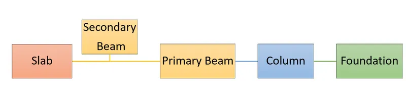
In the reinforced concrete structure building the load transferred from top to bottom. The load transfer procedure flowchart is as-
3.1. Differentiate One-Way and Two-way slabs. Elaborate each slab type.
|
One-way slab |
Two-way slab |
|
Slab are supported by beams on the two opposite side |
Slab are supported by beams on all the four sides |
|
Main reinforcement is provided on shorter span due to bending |
Main reinforcement is provided on both side as bending occurs on both sides. |
|
Load are carried along one direction |
Load are carried along both the direction |
|
If L/b ratio is greater than or equal to 2,then the slab is considered as the One-way slab |
If L/b ratio is less than or equal to 2,then the slab is considered as the Two-way slab |
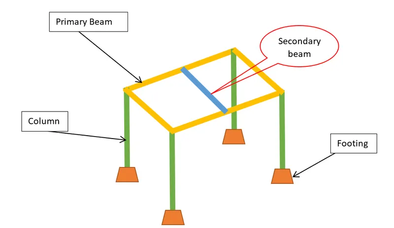
3.2 Explain the concept of secondary beams with proper sketch.
Secondary beams are those which run between beams. They rest on primary beams. Secondary beam transfers the load to the primary beam. Secondary beam are provided for supporting and reducing the deflection on beam and slab.
3.3 Mention the Primary load cases.
a. State the Indian Standards for each load case
- Dead Load (IS 875:Part I)
- Live Load (IS 875:Part II)
- Superimposed Dead Load (IS 875:Part I)
- Seismic Earthquake Load (IS 1893: 2016)
b. Detail the parameters of each load case:
Dead Load/ Superimposed: Dead loads are structural loads of a constant magnitude over time. The dead load is defined as the permanent load in a structure. Superimposed load covers floor finishes and service load.
Live Load: Live loads may vary over time. This is a temporary load. Typical live loads might include the weight of the audience in an auditorium, the books in a library, traffic loads and so on. Live loads on floors and the roofs consist of all loads which are temporarily placed on the structure.
Earthquake Load: Earthquake loads or seismic loads are also an important load case that needs to be considered while designing and analysing of the high-rise structure of the building.
c. Brief each load case:
- Cement : 1440 Kg/m³
- Steel : 7850 Kg/m³
- Sand : 1600 Kg/m³
- Concrete : 2400 Kg/m³
- Soil : 1800 Kg/m³
Live Load:
- For residential building we use 3kN/m² Live Load.
- All rooms and kitchen- 2 kN/m²
- Bathrooms and Toilets- 2 kN/m²
- Balcony- 3 kN/m²
- Staircase/Corridors- 3 kN/m²
Earthquake Load:
And according to the codal provision, the dynamic seismic analysis can be carried out via any of the two methods and these two methods are spectrum analysis and the time history analysis.
4. Detail the steps involved in assigning Properties and Support to a model using STAAD Pro sequentially.
- Create Modal
- Define Property of Structure
- Goto Properties tab, click on Define
- Select require shape of structure and provide dimension
- Select material of structure
- Assigning Support
- Goto Support tab, click on Create
- Add supports as requirement
- Assign to the Structure
5. Brief the steps to be followed to create and assign secondary beams in STAAD Pro.
- We have to defined the secondary beam between the primary beam
- By using insert node, we can draw the beam perpendicular to the secondary beam
- We have to release the both ends moment on the secondary beam
- Click on secondary beam, go to specification tab
- Select the beam from specification dialog box
- In the release tab, release the FX & MZ from start and end location
- In the secondary beam small circle will visible its mean releases the moment at end
- Assign to the secondary
Practical
1. Calculate the wind pressure for the given building
a. Building Dimension : 20m x 30m x 20m height RCC
b. Building usage : Hospital block in city centre
c. Location : Darjeeling
PROCEDURE:
STEP 1) Calculate Design Wind Speed: (IS:875-1987 Part-3)
- Basic Wind Speed Vb = 47m/s (Darjeeling)
- Risk Coefficient k1 = 1.07 (Hospital Building)
- Terrain roughness k2 = 0.80 Category 4 (City Center very closed building)
- Topography Factor k3 = 1 (consider less than 3-degree undulated surface)
- Design Wind Speed Vz
Vz = Vb k1 k2 k3
Vz = 47 x 1.07 x 0.80 x 1
Vz = 40.23 m/s
- Design Wind Pressure Pz
Pz = 0.6Vz2
Pz = 0.6x40.23x40.23
Pz = 0.97 kN
2. Calculate the Dead load and Live load for the above building with reference to IS standards (assume suitable sections).
Assume the Dimensions of Structural Member-
Column size : 0.6m x 0.6m
Beam size : 0.45m x 0.6m
Slab thickness : 0.150m
Floor height : 3.3m
Dead Load/ Superimposed Dead Load on typical Floor
Interior Partition :1 KN/m²
Floor Finish :2.20 KN/m²
MEP Service :0.50 KN/m²
Insulation And Water Proofing :0.2 KN/m²
Parapet Wall :0.20 KN/m²
Miscellaneous :1 KN/m²
Total Dead Load On Typical Floor 5 KN/m²
Calculation of the Live Load-
As per IS: 875 (Part 2) - 1987 the live load of the Hospital buildings
Ward rooms :2.0 KN/m²
Office and OPD Room :2.5 KN/m²
Laboratory :3.0 KN/m²
Lift machine room :7.5 KN/m²
Toilets and Bathrooms :2.0 KN/m²
Staircase :4.0 KN/m²
Corridor and Passages :4.0 KN/m²