Week 3 Challenge
1.1 The primary load cases that are to be considered for design are listed below:
- Dead Load (IS 875: Part I).
- Live Load (IS 875: Part II).
- Wind Load (IS 875: Part III).
- Snow Load (IS 875: Part IV).
- Seismic Load (IS 1893: 2016).
1.2 ONE-WAY SLAB :
- One-way slab is a plane surface of uniformly loaded which deforms into a cylindrical shape and hence the bending moment develops only in one direction. These type of slab is called one-way slab.
- One-way slab is a slab in which the ratio of the longer span to its shorter span is more than or equal to 2.
- One-way slab load distribution takes place along its shorter span.Hence bending also happens at the shorter span of the slab.
1.3 The value of unit weight of structural steel and soil are given below:
- Unit-weight of Structural Steel: 7850 Kg/cu.m.
- Unit-weight of soil : 18kn/m^3
1.4 Few sections that can be defined using Properties tab in STAAD Pro are listed below:
- Circular sections.
- Rectangular sections.
- I-Sections.
- T-Sections.
- Tapered-I sections.
- Trapezoidal sections.
- Custom Geometric Sections.
1.5 Primary Beams :
- The primary beams are the beams that are directly connected with the column on both the ends.
- The function of the primary beams are to transfer the load of the slab directly to the column that they are resting on.
RESULT :
- 1.1- Stated the primary load cases to be considered for design.
- 1.2- Defined One – Way slab.
- 1.3- Mentioned the value of unit weight of structural steel and soil?
- 1.4- Named few sections that can be defined using Properties tab in STAAD Pro.
- 1.5- Defined Primary Beams.
2.1 The factors that influence the design presure intensity of a high rise building are
`Pz =0.6 Vz^2`
Where
- Pz = Design wind pressure
- Vz = Design Speed
The factors and parameters that influence the design pressure intensity of a high-rise building are:
`Vz = Vb x K1 x K2 x K3`
Where
- Vb = Wind Speed
- K1 = Probability Factor
- K2 = Terrain, Height and Structure size factor
- K3 = Tropography Factor
2.2 The load transfer procedure of a reinforced concrete building has been illustrated below in the form of the flowchart,
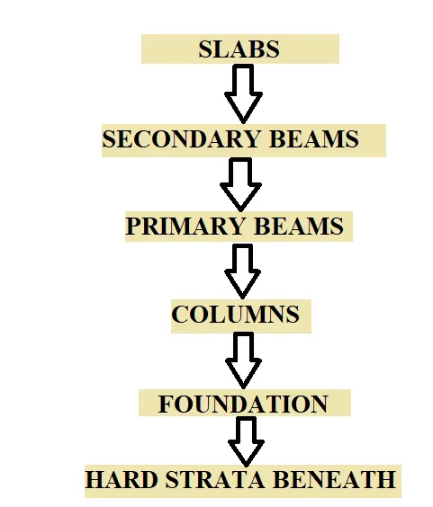
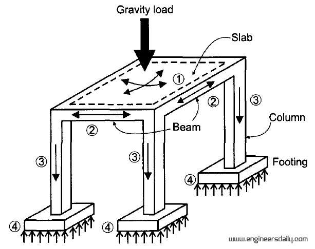
RESULT :
- 2.1- Stated the factors and parameters that influence the design pressure intensity of a high-rise building.
- 2.2- Mentioned the load transfer process of a Reinforced Concrete Building.
3.1 Differentiate One-Way and Two way slabs. Elaborate each slab type.
| SL NO | One-Way Slab | Two-way Slab |
| 1 | The one-way slab can be defined as the type of slab in which the ratio of the longer span to the shorter span is greater than two. | The two-way slab can be defined as the type of slab in which the ratio of the longer span to the shorter span is less than two. |
| 2 | The bending moment occurs only in one direction. | The bending moment occurs in two directions. |
| 3 | L/B ratio is greater than 2. | L/B ratio is less than 2. |
| 4 | In a one-way slab, the crank is provided in two directions | In a two-way slab, the crank is provided in four directions. |
| 5 | In a one-way slab, the main reinforcement is provided in a short span and distribution reinforcement is provided in a long span | In a two-way slab, the main reinforcement is provided in both directions |
| 6 | The one-way slab is supported by a beam on two opposite sides only. | The two-way slab is supported by the beam on all four sides. |
| 7 | direction perpendicular to the supporting beam. | In a two-way slab, the load is carried in both directions. |
| 8 | The one-way slab is economical up to a span of 3.6 meters. | The two-way slab is economical for panel sizes up to 6m x 6m. |
| 9 | In a one-way slab quantity of steel required is less. | In a two-way slab quantity of steel is more as compared to the one-way slab. |
| 10 | It is mostly used for culverts, bridges, etc | It is mostly used for residential buildings, water tanks, etc. |
3.2 SECONDARY BEAM :
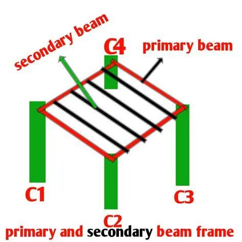
The secondary beams are primarily connected to the primary beams mainly simply supported beams.
- The secondary beams are provided for the better distribution of slab loads along with the primary beams which rests on thed slabs.
- So mainly the secondary beams are the beams that are not directly connected to the columns. The secondary beams rest on the other beams that are directly rest on the column and those beams are known as the primary beams.
- So the secondary beams carries a certain amount of total load and help them to distribute the loads in the respective manner.
- In secondary beams,it is important to release the end moments at the supports,because of this all the secondary beams are provided with the pinned connection.
3.3 Primary load cases
a. State the Indian Standards for each load case:
- Dead Load (IS 875:Part 1).
- Live Load (IS 875:Part 2).
- Wind Load (IS 875:Part 3).
- Snow Load (IS 875:Part 4).
- Earthquake Load (IS1893:2016).
b. Detail the parameters of each load case:
- Member Loads.
- Concentration Loads.
- Floor Loads.
- Plate Loads.
c. Brief each load case:
Dead Load:
- The dead load is defined as the continuous load in a structure i.e the load of machine etc and this load caused by the weight of the members that are pemanently attached to the particular structure.
- The dead load of the structure comprised of the load of the column, load of the beam , loads of the floor slab, roofing,walls, the load of the windows or may be the load of the electrical fixture. All the loads which is permanent on the structure is called as the dead load of the structure.
Some of the Dead Load(Unit Weight) of the following materials:
- Cement : 1440 Kg/cu.m.
- Steel : 7850 Kg/cu.m.
- Sand : 1600 Kg/cu.m.
- Concrete : 2400 Kg/cu.m.
- RCC : 2500 Kg/cu.m.
- Soil : 1800 Kg/cu.m.
Dead Load factor is 1.
Live Load:
- Live loads are the loads that are fully or partially vary from time to time on the structure.
- Live loads are not constant loads throughout of the life span of a structure.
- Live loads may vary time to time according to its usage or the occupancy.
- Live load may vary depend on the type of the structure such as the residential building,commercial building,industrial building etc.
- For residential building we use 3KN/sq.m Live Load.
- Live loads on floors and the roofs consist of all loads which are temporarily placed on the structure. Some of the live loads (Unit Weight) are:
- All rooms and kitchen : 2 KN/sq.m.
- Bathrooms and Toilets : 2 KN/sq.m.
- Balcony : 3 KN/cu.m.
- Staircase/Corridors : 3 KN/cu.m.
Wind Load:
- Wind Load is a force on a structure that is arising from the impact of the wind. Wind load is an important load case for the structure. We considered this type of load where the structure are situated or located in the hilly areas of the mountain areas where we can expect high speed of the winds that can affect the structure. In those areas we need to consider the wind loads.
- Mainly we calculated the wind loads for the roofs of the structure.
Earthquake Load:
- Earthquake loads or seismic loads are also an important load case that needs to be considered while designing and analysing of the high-rise structure of the building.
- Mainly we considered this type of loads where there are high chances of earthquakes or we can say we have to consider this load in the earthquake prone areas,where there is a high risk of earthquake.
- And according to the codal provision,the dynamic seismic analysis can be carried out via any of the two methods and these two methods are spectrum analysis and the time history analysis.
3.4 Assigning Properties :
The steps that are involved in assigning the properties and support to a model using the STAAD Pro software have been discussed below:
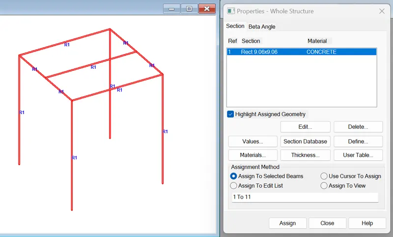
- The first step in order to assigning the properties to a model in a model using STAAD Pro software,go to the Properties tab and then there will be a dialoige box and in that dialouge box there is an option called Define menu just click on that option.
- After clicking the define option there will be another dialouge box,in that dialouge box there will be a list of existing sectional properties,from that list choose the desired sectional property like Circular section,Rectangular section,Trapezoidal section etc.
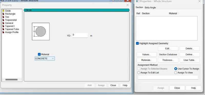
- After choosing the section properties specify the dimensions in that dialouge box.
- And now there will be another option called Add just click on that option and then click OK.
- And now assign the property to the model or structure,and to assign the property select the section that we have just created from the created section,and click on the opion Assign to the selected view and then click on the assign option and then assign the property and done.
Assigning Support :
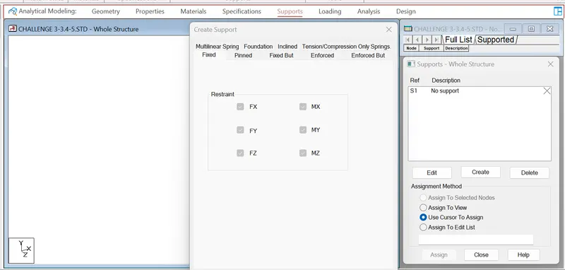
- In order to assign the Support to the model using the STAAD Pro software,go to the Section tab and then there will be another dialouge box and in that dialouge box there will be an option called Create New just click on that option.
- After clicking on that option there will be another dialouge box and in that dialouge box there will be another options like Fixed,Pinned,Fixed But etc.
- Click on the desired end conditions,then there will be an option called Add just click on that option.
- And now assign the Support to the model or structure,and to assign the support select the support that we have just created from the created section,and click on the opion Assign to the selected view and then click on the assign option and then assign the property and done.
3.5 The steps that are involved in creating and assigning the secondary beams in STAAD Pro are discussed below:
- First create a simple model by using node in staad Pro
- Click on Create beam option and create a beam in the direction of x and z axis
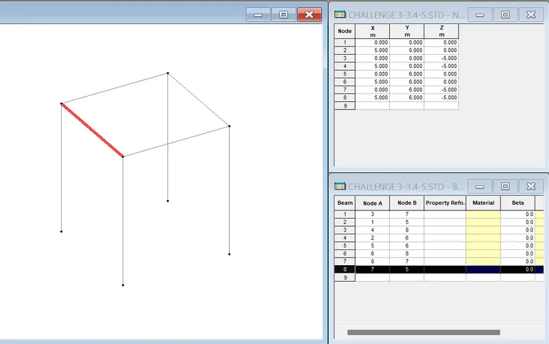
- Click on the primary beam in the section
- Right click and add new node in the beam section a node will be added
- Click on the create beam
- Add New beam between Nodes.
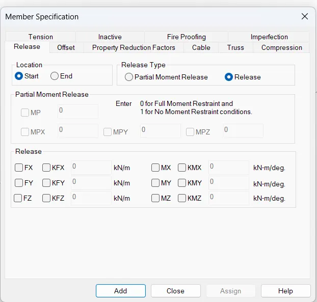
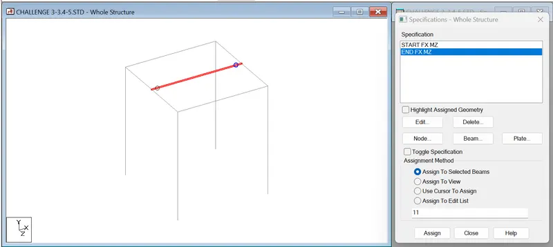
- Go to the Specification
- Select Beam, Member Specification dialogue box opens
- Click on Release
- Click on Start and Tick on Fx and Mz and click Add.
- Now Click on End and Tick Fx and Mz and click Add
- Now Assign to the selected Beam
RESULT :
- 3.1-Differentiated One-Way and Two way slabs.
- 3.2-Explained the concept of secondary beams with proper sketch.
- 3.3-Mentioned and elaborated each load case.
- 3.4-Explained the steps involved in assigning Properties and Support to a model using STAAD Pro sequentially.
- 3.5-Explained the steps to be followed to create and assign secondary beams in STAAD Pro.
PRACTICAL :
Given :
Building dimensions:- 20mx30mx20m.
Buidling usage:- Hospital Block.
Location of the building:- Darjeeling.
Calculate Design Wind Speed :
We know the formula to calculate the design wind speed,that is:
- Vb= Basic wind speed (m/s)
- k1= Risk co-efficeint
We can find the value of risk co-efficent k1, from IS875:Part 3 2014 table 1
- K2=terrain Roughness and hight factor
- K3=toptgraphy Factor
We can find the value of topography factor, from IS875:Part 3 2015 clause no 6.3.3
- k4=impartance factor
Given Data form the IS code:
- Vb=50ms
- k1=1
- k2=0.8
- k3=1
- k4=1
Calculation :
`Vz=Vb⋅k1⋅k2⋅k3⋅k4`
`Vz=50*1*0.8*1*1`
`Vz=40ms`
Calculation of Wind pressure:
- `Pz=0.6⋅Vz^2`
- `Pz=0.6⋅(40)2`
- `Pz=960N`
- `Pz=0.960kN`
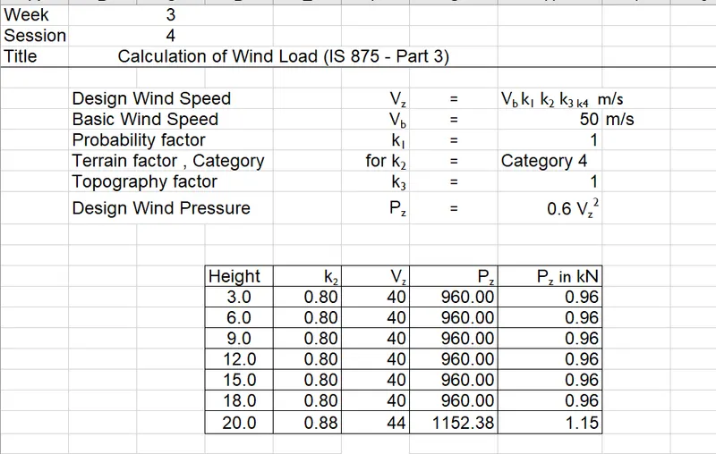
Similarly,we can calculate the for different heights,the calculation for different height has been done in the excel sheet so the excel sheet has been given below:
2. Calculate the Dead load and Live load for the above building with reference to IS standards
- Unit Weight of Concrete = 25 KN/m^2
- Unit Weight of PCC = 22 KN/mm^2
- Unit Weight of Brick Wall = 18 KN/m^2
Perimeter of building = 20+20+30+30=100m
SELF WEIGHT OF BUILDING:
= (Weight of one Slab x 7) + Weight of Wall
= (25 x 0.150 x 30x20X7) + (18 x 3 x 100 x 0.23X5) + ( 18 x 2 x 100 x 0.23X1)
= 22788 kN
LOADS ON FLOOR SLAB:
- Interior partitions = 1 kN/m^2
- Floor Finish(100mm) = 2.2 kN/m^2
- Miscellaneous = 0.5 kN/m^2
- Total SDL = 4.0 kN/m2
- RC Parapet wall at Roof level = 5 kN/m
= 5x100(perimeter of building = 20+20+30+30=100m)
= 500 kN
Total SDL = 4x20x30
= 2400 kN
Total Dead load =22788 + 2400 + 500
= 25688 kN
LIVE LOAD :
Assume live load = 3kN/m^2
Live Load = 20 x 30 x 3 = 1800 kN
Total Live Load = 1800 x no of floors
= 1800 x 6
= 10800 kN
RESULT :
- P1. Calculated the wind pressure for the given building
- P2. Calculated the Dead load and Live load for the given building with reference to IS standards.
- Total Dead load = 25688 kN
- Total Live Load = 10800 KN