Topological cleanup, surface, and volume mesh generation on the turbocharger assembly using ANSA
Aim:
1. To check geometrical errors and perform topology cleanup on the given turbocharger geometry to create appropriate volumes.
2. Assign appropriate Property IDs (PIDs) to different components of the model and deploy surface mesh on it with the given target lengths.
3. Deploy volumetric mesh on the required volumes (CFD mesh).
Problem statement:
To check for geometrical errors and perform topology cleanup to make appropriate volumes. Create and assign PIDs and perform surface mesh with the given target lengths as per PIDs. The target lengths for the PIDs are as follows:
- Blade stage-1 = 1 mm
- Blade stage-2 = 1 mm
- Impeller = 2 mm
- Shaft rotor = 1 mm
- Turbo casing = 5 mm
- Compressor casing = 5 mm
- Inlet casing cover = 5 mm
Finally, deploy the volumetric mesh for the required volumes (CFD mesh).
Solution:
1. Import the given turbocharger model into ANSA
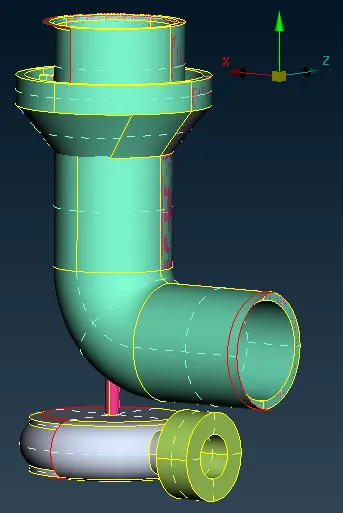
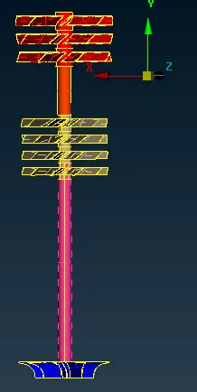
2. Topology cleanup is done on the model. First, the overlapping surfaces are deleted, next, the missing surfaces are redrawn, and appropriate Property IDs (PIDs) are provided to different parts of the geometry. The parts- blade stage1 and 2, impeller, and the shaft are in contact with each other. They are separated from each other by faces. These faces are deleted so that ANSA considers this assembly a single volume and hence saving time while deploying the volume mesh.
3. Since the deployment of the volume mesh requires a closed geometry, the inlets, outlets, and other open surfaces in the given geometry are closed using the fill hole command. This leads to the formation of a triple con at that location. This triple con is not an error since it is clear that there are no overlapping faces, but three faces from different directions are in contact with one edge.
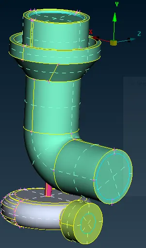
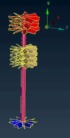
4. Once the topology cleanup is done, the surface mesh is deployed. The mesh target lengths for PIDs are as follows.
- Blade stage-1 = 1 mm
- Blade stage-2 = 1 mm
- Impeller = 2 mm
- Shaft rotor = 1 mm
- Turbo casing = 5 mm
- Compressor casing = 5 mm
- Inlet casing cover = 5 mm
The mesh will not be deployed on the regions which are in contact with each other and having different mesh target lengths. To resolve this issue, the cons which are in contact with 2 different PIDs are not given perimeter value, and the default value is taken.
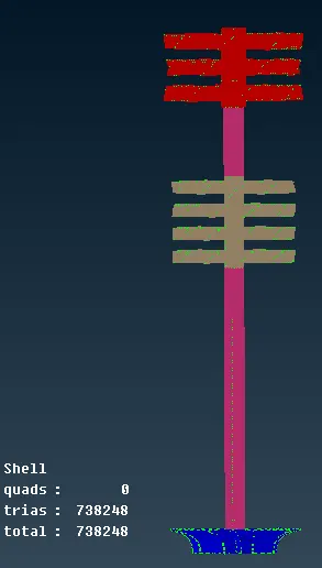
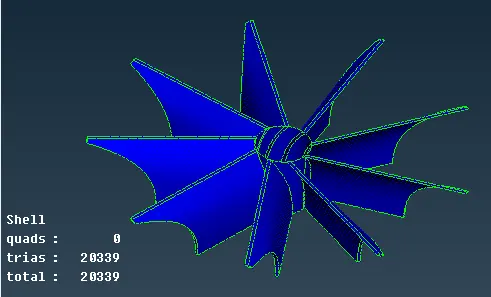
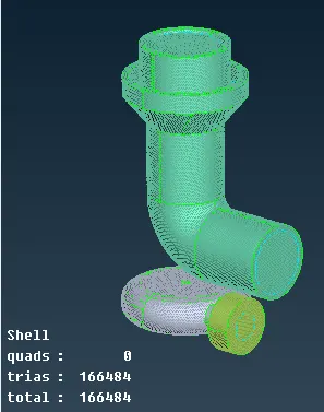
5. Once the surface mesh is deployed on the rotor shaft, compressor casing, and turbo casing, overlapping of the surfaces is observed. This can be resolved by first, deleting the overlapped surface and then use the intersect option to create a con the intersection region, and then re-mesh that surface.
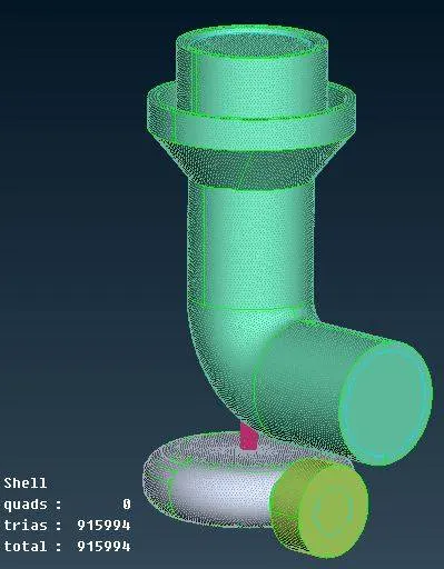
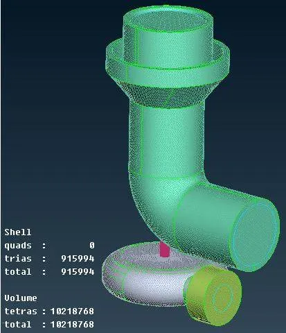
6. Now that we have deployed the surface mesh, the volumetric mesh can be deployed. First, go to the (volumes> define) option in the volume mesh option, so that ANSA detects the respective closed surfaces present in the model which needs to be meshed. Since we are not interested in performing the structural analysis on the model and only interested in performing the CFD analysis, the solid volume detected by ANSA is deleted, and only the fluid volume is retained. We will be remaining with only 4 volumes (fluid volumes), this is meshed by using the tetra CFD option.
Conclusions:
Hence, the topology cleanup and mesh generation (surface and volume) are done on the given turbocharger assembly using ANSA as per the given specifications. Triad and tetra mesh elements were used to generate the surface and volumetric mesh respectively. A total of 915994 triads (surface mesh) and 10218768 tetras (volumetric mesh) elements were generated.