Week 3:- BiW Fixture Design Methodologies Challenges
1. WHAT IS DESIGN METHODOLOGY?
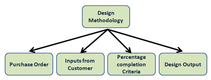
Design methodology is nothing but the steps followed during the concept designing stage of fixture design. Below the steps followed during design methodology.
- Purchase order
- Input from customer
- Percentage completion criteria
- Design output
Purchase order
Purchase order is basically confirmation from customer side that we are ready to start work. A purchase order (PO) Is a commercial document and first official offer issued by a buyer to a seller indicating types, quantities, and agreed prices for products or services
Input from customer
Inputs from customer are major input that we get from customer. We study those input to what king of information get out of it. Customer gives us requirements or specifications of fixture before starting actual design. So we have to design fixture by considering all the points of customer.
Percentage completion criteria
To complete design in time we have to create schedule or time plan called percentage completion. In this we mention all activities related to design and time required to completed that task like concept design , finalized design and 2d of all units in fixture.
Design output
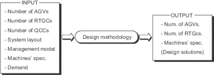
Design output consists lots of data like 3D and 2D documents , VMC IGS files , STEP files and BOM etc .., we Have to give these data to our customer as design output.
2. What are the inputs required from customers to start design a fixture?
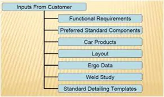
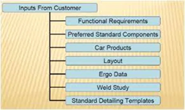
- Functional requirements
The purpose or the function of the fixture will be given as inputs from the customers like what are the process the fixture is go to i.e. welding , riveting , gluing , or whether it is a checking fixture , etc.,.
- Preferred standards
As we know different companies follow different standards , we will be following the standards , we will be following the standards by the customers. By following standards the time of designing and manufacturing of parts will be saved , which will be automatically minimizing the time of the projects.
- Standard like ABB , NAAMS, DESTACO ,ZYTRAN , TUNKERS ARE used IN manufacturing .
- Standards parts like risers , L-blocks ,retainers , pins , NC blocks ,shims , etc.,.
- Car products
The inputs we get car products from the customers are GD&T ,part list , CAD files of car part, clamp plan , product assembly process sheet.
- GD&T
- Its provides information of locating pins , rest ,clamps , damp ,& slide unit information of each stations.
- Parts list
- It gives the list of parts which are going to assembled in the fixture. The list contains the information of part number , part name , revision of fixture , part thickness, etc.,.
- Layout
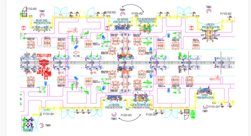
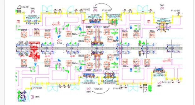
Layout shows the entire assembly plan to understand the process. Layout provides the information of flow of parts , station pitch , robot stations , accessories like tool changers & tip dressers , sub assembly links , plat from height , loading sequence/height
- Ergo study
As name as preferred standards different companies follow different standards of ergo data. We have to follow the customer standards of ergo data.
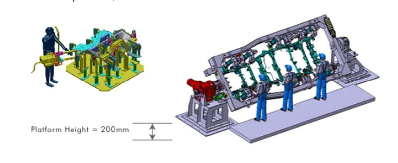
The inputs of ergo data will given by the customer mostly in case of manually operated fixtures / manual fixtures.
The ergo data is mainly to make the operator comfortable which may lead to improve the efficiency in cycle time & production.
- Weld study
Weld study is the important inputs given by the customer.
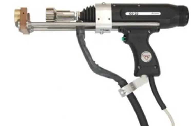
It gives details about the study of particulars gun that we use for welding.
And also the dates like no of weld in the component will be given.
- Standard detailing templates
This inputs include the detailing templates of 2d CAD drawing as per the customer standards. So we have to follow the templates as per the customer standards.
3.What is the inputs we get from car products ?
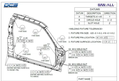
- GD&T
- Its provides information of locating pins , rest ,clamps , damp ,& slide unit information of each stations.
- Parts will often fit together if their dimensions do not fall with in a certain range of values.
- Datum in GD&T
- A datum is theoretical exact plane , axis or point location that GD& T or dimensional tolerances are referenced to you can think of them as an anchor for entire part
- Datum in GD&T
- Parts list
- It gives the list of parts which are going to assembled in the fixture. The list contains the information of part number , part name , revision of fixture , part thickness, etc.,.
- 3D CAD files
- The 3D model of car part will be given from customer. From that 3D model we will be developing our fixture design process.
- The 3D CAD file will be in the format of step file (.stp) ,or IGES (.igs) ,or sometimes it may be in part file (prt)
- Clamp plan
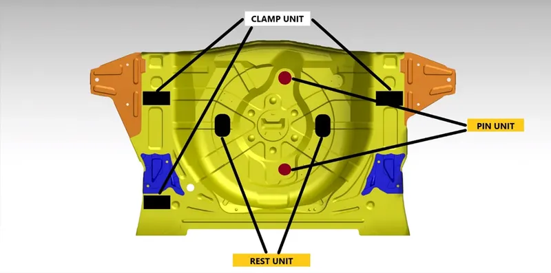
- Clam plan provides the information of location of pins , rest units , clamp units dump etc.,.
- This is the important thing from customer .
- The clamp plan / position should not be changed without the knowledge of customers.
- It gives the details of the exact position of the clamping units
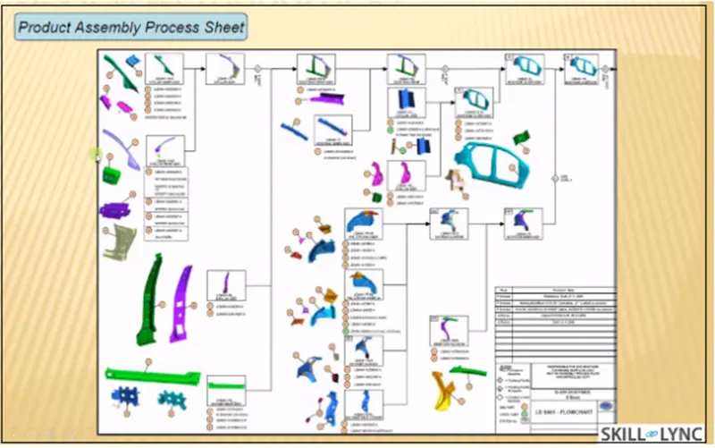
- Product assembly process sheet
- It gives the information of stage wise assembly process like how the parts move from one assembly to another assembly after the completion of joining process.
- It shows the sequence of operations / process to be done in a part or a panel
- Also what are the parts to be joined with the panel will shown in sequence.
4.What is clamp plan?
- Clamps are nothing but a mechanism or component used to hold or clamp job in fixture securely. Clamps are manual type, hydraulic type or pneumatic type depending on customer requirement. Clamp plan mentions or gives the location of clamps in which component is going to clamp . we can’t change clamp location without customers approval, first of all we have to take permission from customers side to change clamp location. Clamp plan also provide information regarding locations of pins , rest , clamps and dumps .
5.What is the purpose of layout?
- Layout is nothing but management of space which helps to understand process of flow of work of entire assembly line.
- Layout is used to achieve more efficiency or co-ordination of 4M’s ( mens , materials ,machines and methods) .plant layout is simply floor plan for arranging machinery and equipment’s present in plant and these things are arranged according to its usage , easy for everyone to use particular equipment’s or machinery , should not disturb flow of material . actually , layout is very helpful to save time and money in plant
6.What is ergo data?
- Every company have standard ergo data and they provide it to fixture designer to designing fixture considering that points Ex height of fixture is decided according to ease while working on fixture
- So we have to design a fixture by considering safety , easy and fool proof design.
- Ergo data is used reduce human errors , increase productivity , human comfort and safety.
- Lets take examples to understand what is ergo data. Height of base unit is decided according to workers posture, height and his comfort . the data related to hight is one of the ergo data and there are several data like this example which are decided by considering human comfort , safety
- .
7.What do you understand by weld study?
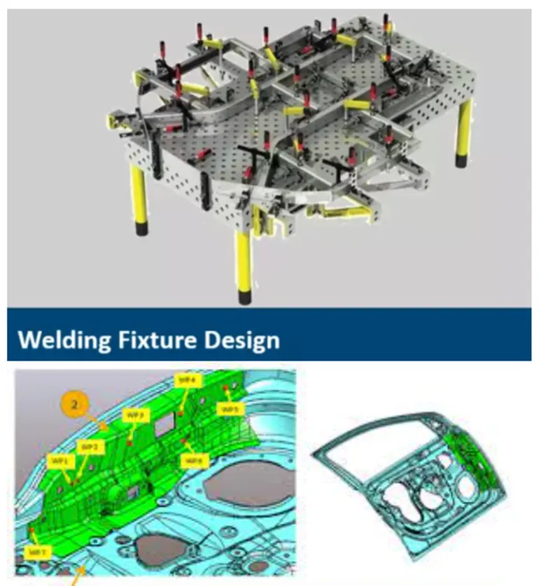
- Weld study is nothing but a study of welding gun that we are going to use in welding fixture and where we are going to weld. It consists study of welding gun details , weld matrix , weld points ,geo weld points and re-spot weld tools ,etc.,.
- Weld gun details: in this we are going to study which type of gun is suitable for particular fixture and selected gun where to use and how to use.
- Weld matrix and weld points: weld points are the points where welding is to be done.
- Geo weld points and re-spot points : weld points are divided using colour code , one of them is red colours points and remaining points has bee green colour. In these , red colour points indicate geo weld points indicate geo weld points which are going to weld in geo tool and green colour points indicate re-spot weld points which are going to weld in re- spot tool.
8.What are the criteria in percentage completion in designing stage ? explain it in detail?
- To complete design in time we have to create schedule or time plan called percentage completion criteria. In this we mention all activities related to design and time required to complete that task like concept design , final finished design and 2D of all units in fixture etc.
- 0-25%( input & concept design ) : In this stage of percentage completion criteria , we have to built concept design of fixture in this stage
- 25 -40% ( concept approval & simulation ) : in this stage , concept design is approval by customer and gives some correction points if any . later we have to give working simulation of fixture for better understanding of how fixture works.
- 40-85% ( design freezing & detailing ): if all requirements and specifications of customers are satisfied then de sign is freezed and detailing works start.
- 85-100% ( check & final dispatch ) : in this stage , quality checking is done using CMM and then dispatched to customers .
9.Breif about output in design:
- Design output consist of lots of data like 3D & 2D documents VMC ,IGES files , STEP files , gas -cut or laser cut files in dwg format and BOM , etc .. we have to give these data to our customer as design output. The basic output are 3D models and 2D drawing fixture .
- Unitised tool: this tool consist of two type of sheets , they are as
Key sheet : key sheet mentioned or shows the location of every units in fixture.
Layout sheet : layout sheet is detail drawing of particular unit in fixture.
Non – unitised sheet : this type of tools don’t require key sheet . Ex stands and tool changer . tools that can stand alone and details in layout sheet.
10.What do you understand by structuring design tree? How does it reduce errors during design process?
- Structuring a design tree is very necessary while designing fixture because it help to identify all manufactured part in hole fixture
- Every customer company have there own standard .
- This will help us during design study . manufacturing to avoid errors
- If we ignore structuring a design tree it will create confusion to avoid errors
11.What are units ? mention its types.
- Unit is nothing but a assembly having specific function like clamping , locating ,and resting . in fixture there are number of units according 3-2-1 principle of location fixture is designed having two major purpose of clamp and locate the component for which fixture is designed .
- Types of units
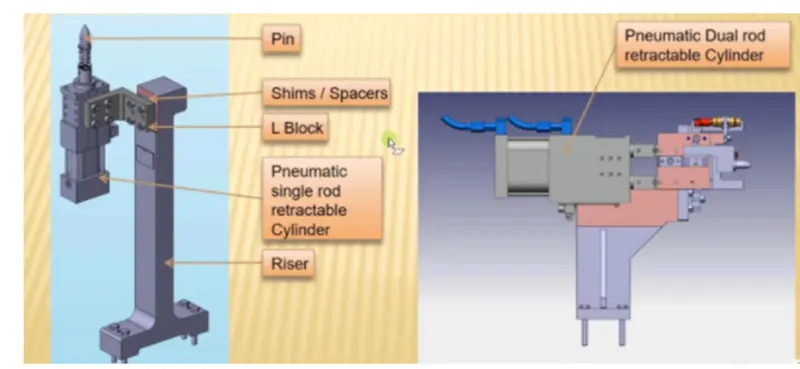
- Fixed pin unit : it is non movable locating unit which arrest movement of component in fixture
- Retract pin unit : it having retracting unit which is used to move pin ensure proper loading and unloading of component
- Rough locator unit: this unit helps operator for correct loading of component
- Rest unit : as name suggest , rest unit is used to rest the component
- Base unit : all the units in fixture are placed on this base unit.
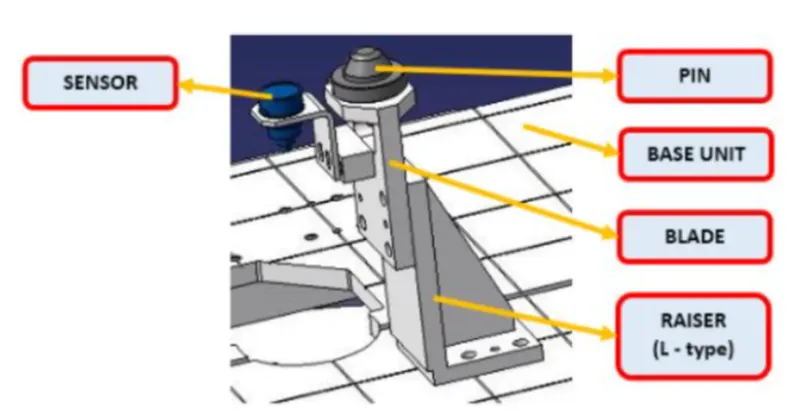
- Describe fixed pin unit and their purpose ?
- This unit is non movable locating unit which arrest movement of component in fixture.
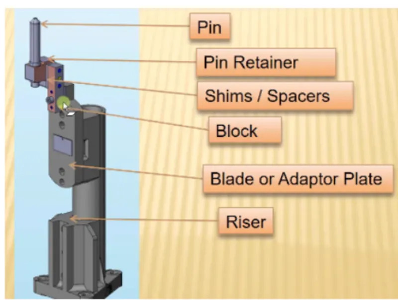
- This picture consist of pin , pin retainer , blade , two way shims , or spacer which control X,Y direction adjustment , block , and risers .
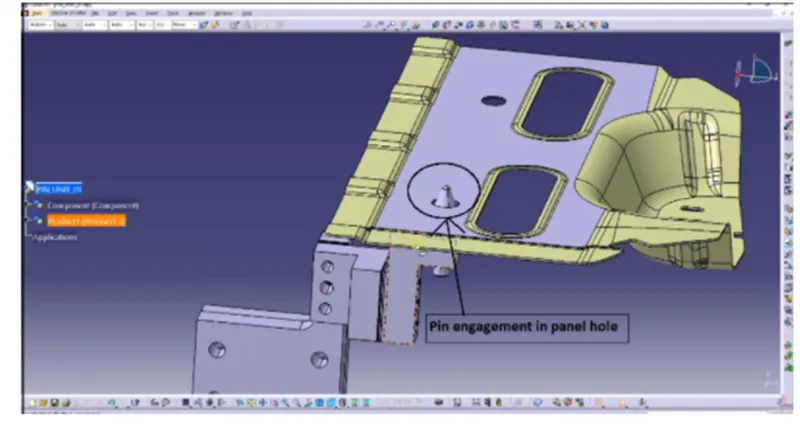
- Purpose of pin unit :
- Main purpose of fixed pin unit is to locate component
- This unit is used to arrest 6 degrees of freedom of component .
- Two pins are used to locate the component . first pin restricts 4 translational motion and other one restricts 2 rotational motion
 13. what are the different parts of fixed pin unit?
- Pin : pin are main part in this type unit because it is used to locate component . 2 pins are used to restricts 8 degrees of freedom .
- Pin retainer : pin retainer are used support or carry pin in it.
- Shims or spacer : these are used to compensate tolerance stack up. In pin unit we need to control two direction that are X & Y using shims and spacer . shims are generally thin sized plates used in group called shim pack and spacer are used as single plate and can be machined accordingly.
- Blade : blades are bolted in risers
- Risers : risers are used to increase height of unit and these are standard parts so need not detailed it or designed it.
- what are the purpose of making a rest unit& describe its parts ?
- Rest unit is one of the simplest unit in fixture used with myler. As rest unit is simple to manufacture and require low cost, hence rest unit is combine with clamp unit and location unit.
- Rest unit parts are following:
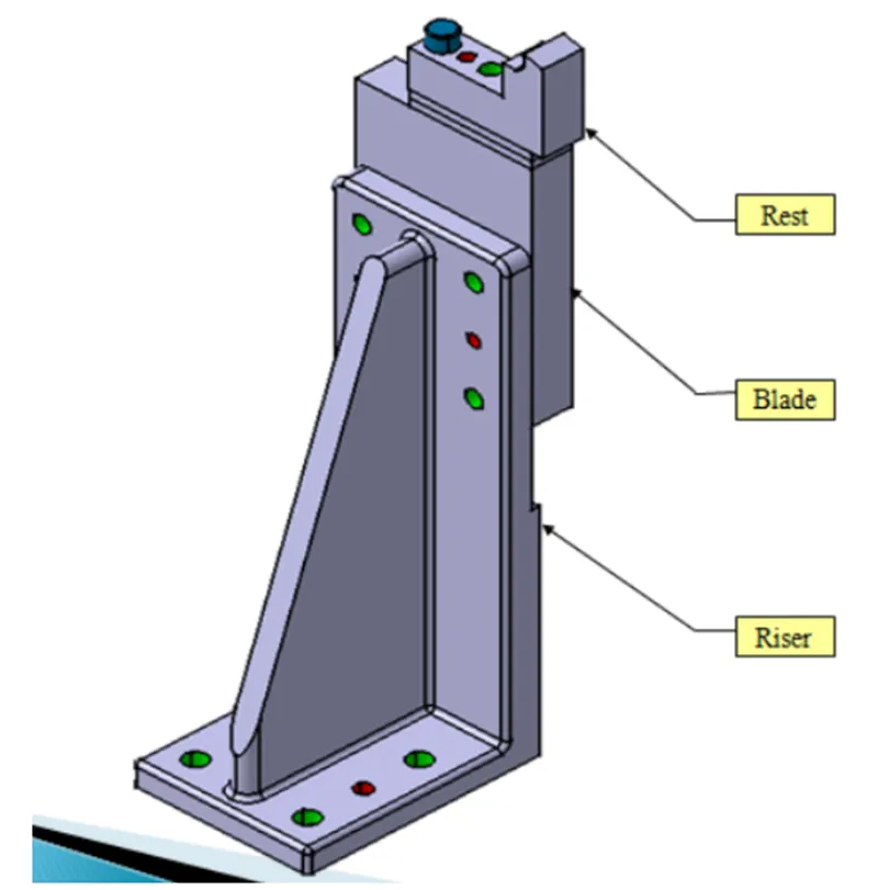
- Riser : riser is used to increase height of unit and these are standard parts so need not detailed it or designed it.
- Blade : blades are bolted on riser.
- Shims or spacer : these are used to compensate tolerance stack up. In pin unit we need to control two direction that are X & Y using shims and spacer . shims are generally thin sized plates used in group called shim pack and spacer are used as single plate and can be machined accordingly.
- Mylars : Mylars are the parts in the rest unit which are in contact with car panel or component used to give support or rest to the component.
- what are the basic fundamentals to design a sensor unit?
- Sensor is a device which detect or measure a physical property. The unit which is built to sense the component or car panel using electrical sensors called unit sensor.
- The output signal of sensor is then send to PLC ( programmable logic controller ) for further process.
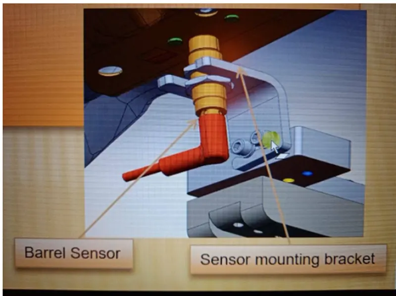
- There are different types of sensors such as proximity sensors laser sensors.
- Fundamentals :
- Each components which are welded in fixture should be sensed. So , we manufactured or assemble component free from errors. Consider an example of car panel having multiple components to assemble using welding. These multiple components are going to sensed to assure correct component is placed at correction position.
16.What is rough locators unit and what are the basic fundamentals to consider while designing it?
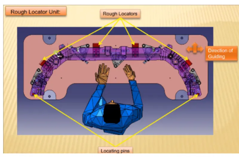
- Rough locators are the parts used to locate component correctly in fixture , basically it guide the operator while loading component in fixture. Figure shows an example of rough locator and different locators we can used. It may be standard part or we can designed it according to our component .
- Fundamentals:
- They are used to guide the component to load correctly in fixture and placed at the edges of component.
- The angle in locator should be according to component.
- Rough locator helps component to placed in pins used in fixture to locate component.
- Entry angle should be 30 to 45 degree and rough locator should start guiding component before 10 to 15mm to start the pin engagement.
- For easy adjustment rough locator mounted on base with two slots in it.
- The direction of slots are in direction of car panel or component.
- what is a base unit and describe its parts?
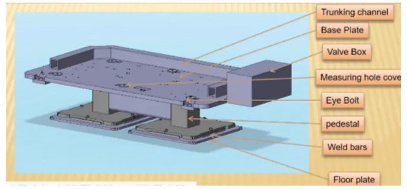
- As name suggest , Base unit is used to provide base for other units such as location unit , rest unit or sliding unit in fixture. These are all mount on this base unit.
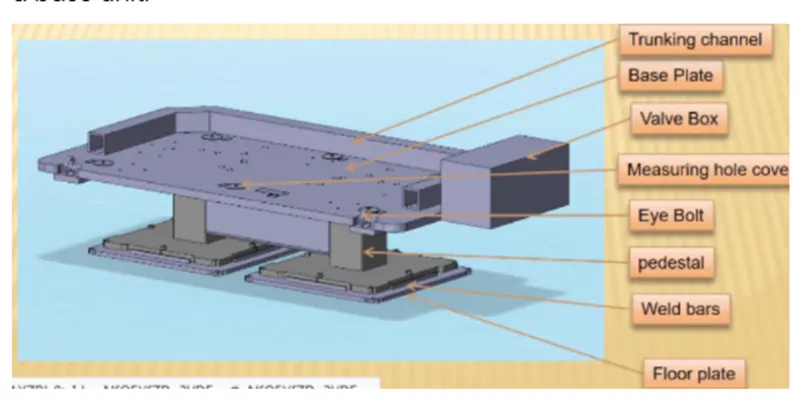
- Part involved in base unit are as below :
- Floor plate: plate which is used to join fixture and floor called floor plate.
- Weld bars and pedestal: these are support or base on which fixture is mounted
- Eye bolt : it is used to move fixture or placed fixture on its place using cables or ropes. This threaded eyebolts is sustain 45 degrees of angular forces
- Measuring hole cover : measuring holes are also known as tooling hole from which other holes on base are drilled. So , measuring holes are basically references holes. These measuring holes are covered using measuring hole cover.
- Base plate: the plate on which all units are mounted called base plate. Base plate is machined on booth to achieve parallism. Thickness of base plate is too thick to sustain load of all units.
- Valve box & trunking channel: pneumatic fixture consist of solenoid valve and these valves are placed inside valve box. Trunking channel protects all pressure in let tube which are attached to pneumatic devices such as cylinders , clamps.
- what is a Dump unit and what are its function?
- Dump unit is used due to lack of space on fixture to built an unit, so , this is a complex unit consist of dump cylinder used for clamping or unclamping of car panel or component.
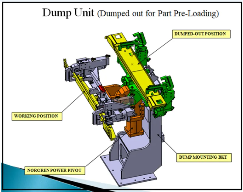
- Function:
- Due to space constrain dump unit used in fixture. It has dump cylinder having open ad close position for better understanding of design. It also has clamp cylinder used for clamping purpose.
- Hence this is too complex unit to built.
- what is slide unit and mention where unit and mention where slide unit are commonly used?
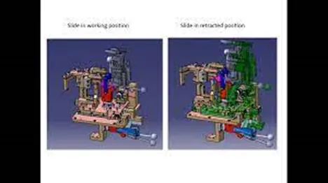
- Slide units are positioning units used to position fixture, units , weld gun , and robots. This unit consist of sliding rail on which entire unit is slide in direction of rails for further operation. Sliding unit consist of open and close position. These sliding unit is commonly used in automotive industry for different similar components. Following is an example of slide unit provided for welding purpose .