Week 2:- BiW Fixture Basics Challenge
BIW BASICS
1 .WHAT IS THE PROCESS OF PROJECT EXCUTION ACTIVITY?
PROCESS OF PROJECT EXECUTION ACTIVITY :
ACTIVITIES:
- This process execution activities is a general activities which is involved in BIW fixture & tooling .
- It’s a starting process for all project management
- It is start with Requirement for Quotation is we received from customer .
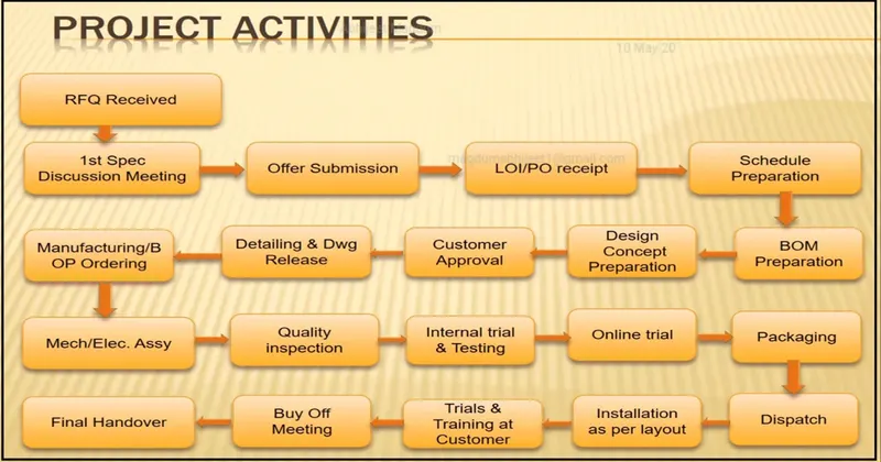
- RFQ – Request for quotation
In this where customer gives the requirement in specifications in detail for the given projects in the form of data or documents
Also customer specifies its technical offer, commercial offers, etc., how the project will be executed & the timeline of the project also will be mentioned
- FIRST SPEC. DISCUSSION METTING:
After RFQ received, technical offer, commercial offer, timeline of the project etc., will be discussed and prepared from our side.
In this time required for data study, 3D design concept, simulation validation, quality check, 2D drawing release , manufacturing , assembly , installation & commissioning will be discussed and prepared in the technical offer .
Based on technical offer, commercial offer will be finalized.
- OFFER SUBMISSION
After the finalization in the meeting the offers will be submitted to customer end .
Customer will arrange to get offer from other suppliers too.
Based on the technical , cost , quality , standard and name in the industries the customer will be finalized the offer
- LOI/PO RECIEPT
After the offer has been finalized customer will be releasing the PO (purchase order )
Once PO is released we have to start the work
After PO from the customer we have to prepare the schedule
- SCHEDULE PREPERATION
Once the PO released from customer we will be working on preparation of schedule which should be matched our planned commitment in the technical offer / customer required time .
Scheduled preparation is nothing but dividing the different activities like kick off meeting , design study , DAP, simulate , quality check , 2D detailing , manufacturing , bought out of electrical & mechanical components , assembly of fixture , paint , trial run out , installation and commissioning at customer and etc
These activities will be discussed in scheduled preparation
- BOM PREPARATION
BOM – Bill of Materials like cylinders , motors , etc., which is required for the project are prepared .
- DESIGNED CONCEPT PREPARETION
Before the design concept , we have to study the data oof customer requirement throughly which is carried out in Design data study activities
During design data study , we will be processed with rough sketches to get a flow while designing concepts
The concepts preparation would include the process like load act on panels , clamping process , which spot should be welded first , travel of the gun .
The weld gun should not collapse while traveling , so by considering this have to make a concept preparation .
To avoid the collapse of weld gun or robots during the travelling . spot plan will be done it initial stage
Spot plan should be take in consider during concept design preparation .
Spot plan clears us that how much robots are to be used and sequence of the spot will be decided along with which robot will be cover certain spot places
- CUSTOMER APPROVEL
It is also known as Design Approval Process (DAP)
After the design concept the customer will be review the design concepts
If the design need to be made simple or some other concept design will discussed and after meeting the requirement of customer . they will give approval to the design to go on with further activities
- DETAILING 7 DRAWING
Once the customer approved the process , the detailing of the fixture parts which is to be manufactured has been done with giving appropriate dimensions and GD&T symbols
All the dimensions which is necessity for manufacturing should be included with GD&T in the drawings to the manufacturing team
- BOP ORDERING
The mechanical & electrical parts like sensors , cylinders , etc ,. Which needs for fixture are ordered as per design specifications
- MECHANICAL / ELECTRICAL ASSEMBLY
After the materials ordered received to our end . the quality will check the working conditions and techniques specs . which meet our requirement
After the quality check the mechanical and the electrical parts are assembled as per design .
- QUALITY INSPECTION
After the assembly again the quality check is done
In this all dimensions , positional accuracy , coordinates are checked using CMM
- INTERNAL TRIAL
After QC check internal trails are made to check the operation
- ONLINE TRAIL
The trail will done in automatic mode through control panel .
The process sequence of operation is checked as by the designed way
- PACKAGING
To avoid damage occur in fixtures while transportation which may also leads to affect the aesthetic look & proper function of fixture packaging has been done
- DESPATCH
After the fixture has been packed for delivery as per standards
It has been despatched to the customer
- INSTALLATION AS PER LAYOUT
As we discussed in design concept preparation , the design of the layout are been prepared at very initial level which gives the information of placements of robots and fixtures
- TRAILS AND TRAINING AT CUSTOMER
Production trails will be taken at customer end
During technical offer we will be confirmed that n-numbers of assemblies will be produced within (8hrs / 12hrs ) shifts
The sequence of working process by the fixture will be explained in detail
- BUYOFF MEETING
After trails and training at customers end , buyoff meeting will be held .
In this meeting customers will give reviews about the fixture .sometime customer may need better to do some addition works also .
These are all discussed in this meeting and finalized the conclusion
- FINAL HANDOVER
In this session the fixture and the document support of the fixture will be handover to the customer
Every automobile industries will follow some standard to maintain document as per ISO , IATF
ISO – organization for international standard
IATF - International automotive task force
- what are the types of joining process?
- JOINING PROCESS:
- Joining comprises is a large no of process used to assemble individual parts into a larger , more complex component or assembly
- Individual parts of a component meet at a joint
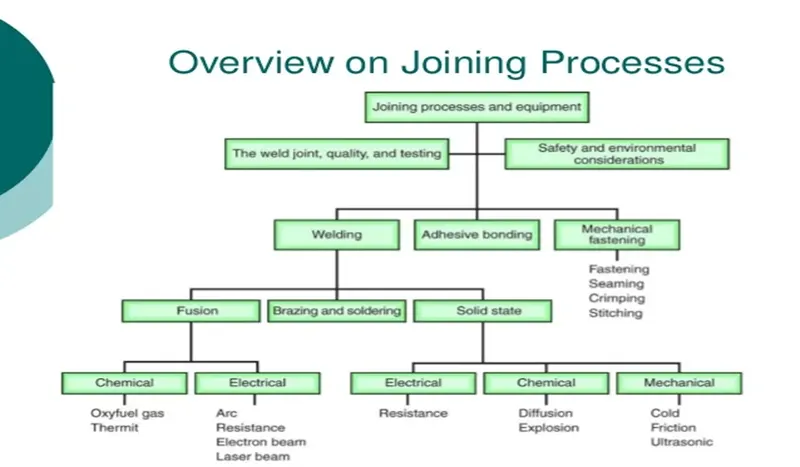
- TYPES OF JOINING PROCESS
- The durability & performance of any structure is largely depends on the quality & the design of the component joints
- Whole structure cannot be made in once
- So there are three fundamentals options for joining materials or components
- Metallurgical joining
- Mechanical joining
- Chemical joining
- METALLURGICAL JOINING
It is classified into three ,
- Welding
- Brazing
- Soldering
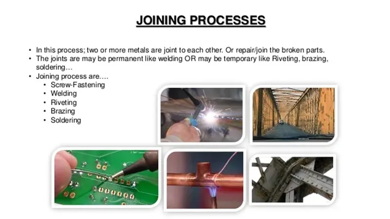
- WELDING
The process of the joining similar metals by the applications of heat is called welding .
Welding can be obtained with or with out application of pressure and with or without addition of filter metal , which is known as electrode
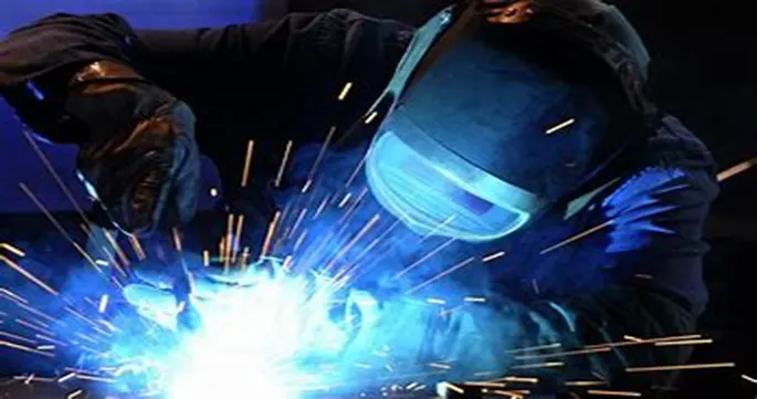
CLASSIFICATION OF WELDING PROCESS
- Fusion welding
- Electric resistance welding
- Solid – state welding
- Fusion welding
In Fusion welding , the metal at the joint is heated to a molten state and then it is allowed to solidify
Pressure is not applied during the welding process and hence it is also called non- pressure welding
Filler materials may be required during this type of welding
- Classification of fusion welding :
- Thermit welding
- Arc welding
- Gas welding
- 2) Arc welding
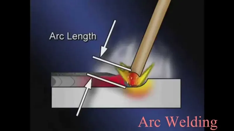
The process involves either consumable or non consumable electrode
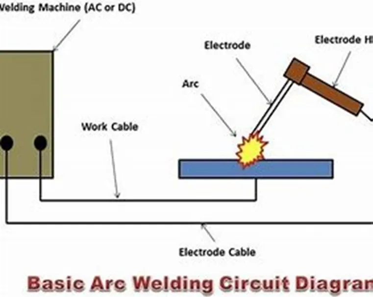
An ARC is produced between tip of the electrode and workpiece to be welded , by use of an A.C or D.C power supply .
The electrode & work piece are brought nearer with similar a small air gap of 3mm approximately .then the current is passed through the work piece and the electrode to produce an electrode arc.
- Types of ARC welding :
- Manual metal arc welding
- MIG welding
- TIG welding
- Sub merged ARC welding
- Plasma welding
- Manual metal arc welding (MMP)
Manual metal arc welding also known as shielded metal arc welding or informally known as stick welding
Stick welding is a process where the arc is struck between the metal rod & workpiece . both the rod & the work piece surface melt to create a weld
- MIG welding :
MIG welding – Metal Inert gas welding
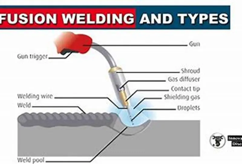
MIG welding is an arc welding technique in which a consumable electrodes used to weld two are more workpiece
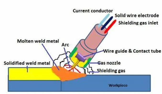
- Used components
- Consumables electrode
- Inert gas supply
- Welding head
- C or D.C power supply
- TIG welding :
TIG welding – tungsten inert gas welding
TIG welding also known as gas tungsten arc welding , is an arc welding method that uses a non consumable tungsten electrode to weld two or more workpiece .
It is very much similar to metal inert gas welding
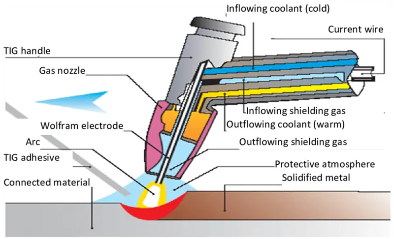
- Used components
- Power supply
- Non – consumable tungsten electrode
- Inert gas supply
- Filler rod
- Welding head
- Electric resistance welding :
Resistance welding is a welding technique widely used in manufacturing industry for joining metal sheets and components
This type of welding is very much used in our BIW assemblies most common
The weld is made by conducting a strong current through metal combination to heat up and finally melt the melts at localized points predetermined by design of the electrodes or the work piece to be welded
- Types of resistance welding
- Resistance spot welding
- Resistance seam welding
- Resistance projection welding
- Resistance spot welding
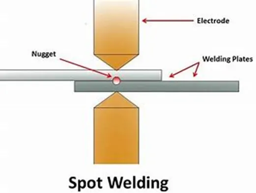
This process is used to joining sheet materials & uses shaped copper-chromium or zirconium alloy electrodes to apply pressure and convey the electrical current through the work piece
Heat is developed mainly at interface between two sheets , eventually causing the material being welded to melt , forming a molten pool , the weld nugget
- Advantages :
Short weld time and also high weld speed
Typically BIW contains 5000 welds
- Resistance seam welding
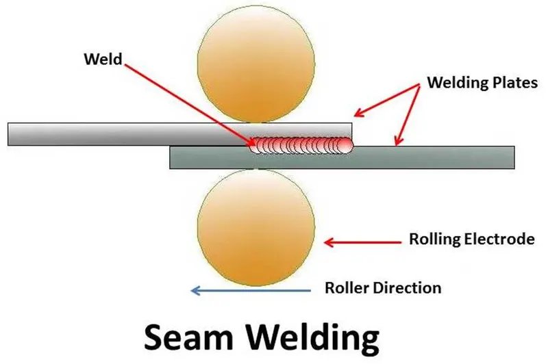
Seam welding is a resistance welding process for joining metal sheets in continuously , often leak tight , seam joints by directly applying opposing forces with electrodes consisting of rotary wheels
- Applications
Mostly use in manufacturing of containers , radiators and heat exchangers
- Projection welding
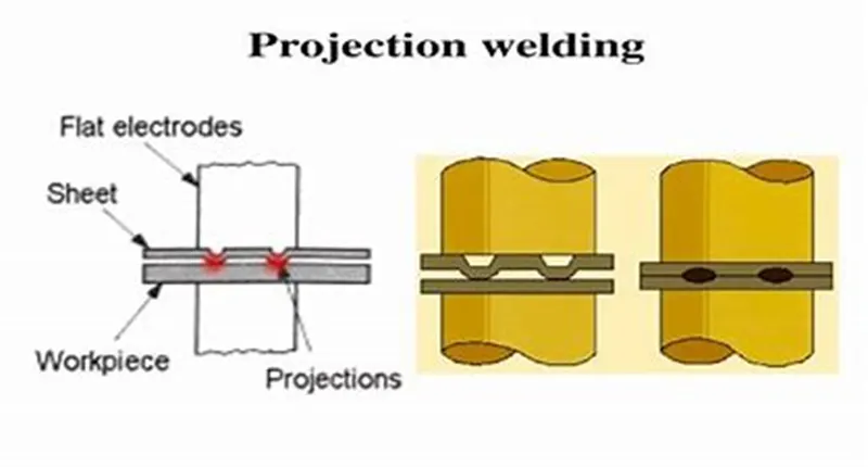
Projection welding is a resistance welding process for joining metal components or sheets with embossment by directly applying forces with electrodes specially design to fit the shapes of the workpieces
- Applications
Used for mechanical fixing of auto body structure (eg). Weld nuts
- BRAZING
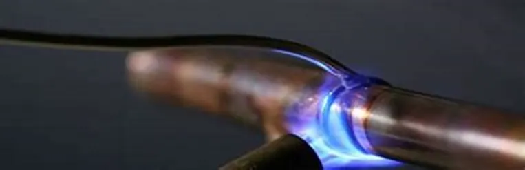
Brazing is a metal – joining process in which two or more metal items are joined together by melting and flowing a filler metal into the joint , the filler metal have a lower melting point than the adjoining metal
- There are different methods in brazing
- Torch brazing
In this method, the acetylene , natural gas & butane or propane are combined with air or oxygen is used to supply the required heat to melt the filler rod and defuse the base metal
- Furnace brazing
In this process , the heat is supplied by gas heating coils. The furnace can be either box type or continuous type
It is used for mass production and fluxes used in the form of paste .
- Resistance brazing
In this process, the filler metal is placed in the joint , rapid heating minimizes oxidation and the heat affected zone is small
- Soldering :
Soldering is a process in which two or more items are joined together by melting and putting a filler metal into the joint , the filler metal having a lower melting point than the adjoining metal
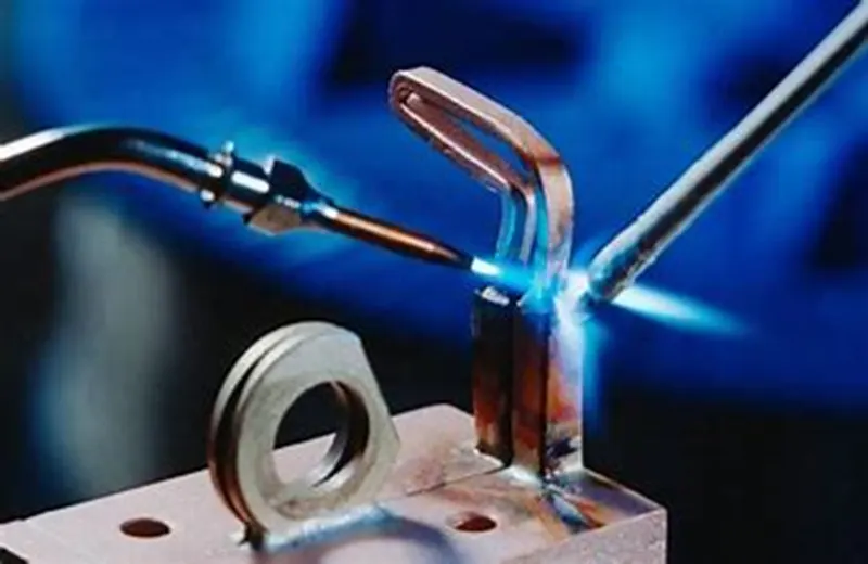
There are different methods in soldering methods
- Hard soldering
In hard soldering , the filler metal is silver . it is also known as silver soldering . this method is more expensive than plain brazing because the filler metal is more expensive
- Soft soldering
This the most commonly used method , in this method soldering iron is a copper rod with a thin tip which is for flattering the soldering material .the soldering iron can be heated by keeping in furnace or by means of an electrical resistance .
The filler material used in soft soldering is called as soft solder.
- Infrared soldering :
In this method , the ultrasonic waves are used to join the metals
- Resistance & induction soldering :
In this method , the electric energy is used to join the metals
- Wave soldering
It is a different method in which the parts to be soldered is not dipped into the solder tank but wave is generated into the tank
- Dip soldering :
In this method , a large amount of solder is melted in a closed tank .then the parts to be soldered are cleaned & properly dipped in flux bath as per the requirement .
- MECHANICAL JOINING
Mechanical joining includes bolting , caulking , riveting , shrink fitting , hemming , seaming and folding , all of which join workpieces by using mechanical energy .
It is classified into 4 methods
- Riveting
- Hemming & seaming
- Bolting
- Shrink fitting
- RIVETING
It is a high speed mechanical joining process for point joining sheet material , typically steels &aluminium alloys .
It is a single step technique generally using a semi tubular rivet to clinch the sheets in a mechanical joint .
As the name suggests pre-drilled holes are not required , allowing the joint to be made rapidly in one operation .
- HEMMING & SEAMING
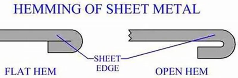
Hemming & Seaming are two similar metal working process in which a sheet metal edge is rolled over onto itself .
Hemming is a process in which the edge is rolled flush to itself , while a seam joins the edges of tow materials
- BOLTING
Bolted joints are one of the most common elements in construction and machine design . they consist of fasteners the capture and join other parts , and are secured with the mating of screw threads . there are two main types of bolted joint designs , tension joints and shear joints . in the tension joint , the bolt and clamped components of the joint are designed to transfer an applied tension load through the joint and bolt stiffness .
- SHRINK FITTING
Shrink fitting is a technique in which an interference fit is achieved by a relative size change after assembly . this is usually achieved by heating or cooling one component before assembly and allowing it to return to the ambient temperature after assembly , employing the phenomenon of thermal expansion to make a joint . for example , the thermal expansion of a piece of a metallic drainpipe allows a builder to fit the cooler piece to it .
As the adjoined pieces reach the same temperature , the joint becomes strained and stronger .
- CHEMICAL JOINING :
Chemical joining includes adhesive bonding’s.
ADHESIVE BONDING
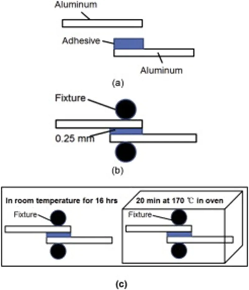
- Adhesive bonding is used to fasten two surfaces together usually producing a smooth bond.
- This joining technique involves glues , epoxies or various plastic agents that bond by evaporation of a solvent or by curing a bonding agent with heat , pressure or time
- The procedure enables bonding temperature from 1000C down to room temperature .the most important process parameters for achieving a high bonding strength are:
- Adhesive material
- Coating thickness
- Bonding temperature
- Processing time
- Chamber pressure
- Tool pressure
- Adhesive bonding has the advantages of relatively low bonding temperatures as well as the absence of electric voltage and current .
- The possibility of corrosion due to out – gassed products , thermal instability and penetration of moisture limits the reliability of the bonding process .
- Another disadvantage is the missing possibility of hermetically sealed encapsulation due to higher permeability of gas and water molecules while using organic adhesives .
3.What is resistance welding & its application in the automotive sector?
ELECTRIC RESISTANCE WELDING :
Electric resistance welding :
Resistance welding is a welding technique widely used in manufacturing industry for joining metal sheets and components .
This type of welding is very much used in our BIW assemblies most common
The weld is made by conducting a strong current through metal combination to heat up and finally melt the melts at localized points predetermined by design of the electrodes or the work piece to be welded .A force is always applied before , during and after the application of the current to confine the contact area at the weld interfaces and in some applications to forge the workpieces . resistance welding is used in mass production for welding sheet metals , wire & tubes . it Is also used in welding bars , boxes, cans , rod pipes , & frame metals of medium & high resistance such as steel , stainless steel , Monel metal & Silicone bronze which are easy to weld .
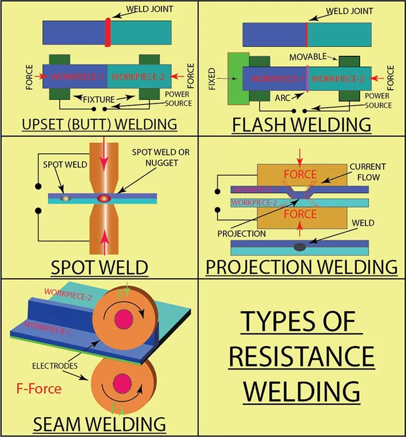
Types of resistance welding
- Resistance spot welding
- Resistance seam welding
- Resistance projection welding
- Resistance spot welding
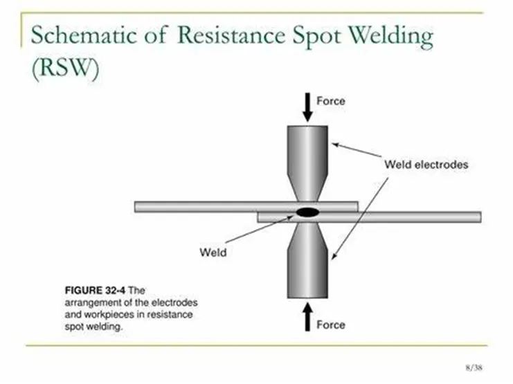
- This process is used to joining sheet materials & uses shaped copper-chromium or zirconium alloy electrodes to apply pressure and convey the electrical current through the work piece .Heat is developed mainly at interface between two sheets , eventually causing the material being welded to melt , forming a molten pool , the weld nugget .
- The molten pool is contained by the pressure applied by the electrode tip & the surrounding solid metal .
PRINCIPLE OF SPOT WELDING
- The resistance spot welding process uses two copper alloy electrode to concentrated weld current and forced between work to be welded .
- Produce coalescence in one spot for heat generated from resistance to the electrical current through workpiece held together under pressure by the electrode . it process usually the thickness range of sheet metal is 0.5 to 3.0 mm, the small spot is quickly heated until the melting point , in this reason a nugget of welded metal after power supply is removed .
Advantages :
- Short weld time and also high weld speed
- Typically BIW contains 5000 welds
- Highly adaptable to automation & robotics
- Strength & durability of automobile largely depends on the quality of RSW
Disadvantages :
- The electrodes have to be able to reach both sides of the pieces of metal that are being joined together.
- . A particular spot welding machine will be able to hold only a certain thickness of metal , usually 5-50 inches , and through although the position of the electrodes can be only a limited amount of movement in most electrode holders .
- Working and a loss of fatigue strength can occur around the point where metal has been spot welded . the appearance of the join is often ugly , and there can be cracks .
Applications
The most common application of the spot welding is in automobile manufacturing industry . where it is used almost universally to weld the sheet metal to form a car
Spot welding is also used in the orthodontist’s clinic , where small scale spot welding equipment is used when resizing metal “ molar bands “ used in orthodontics.
Resistance seam welding
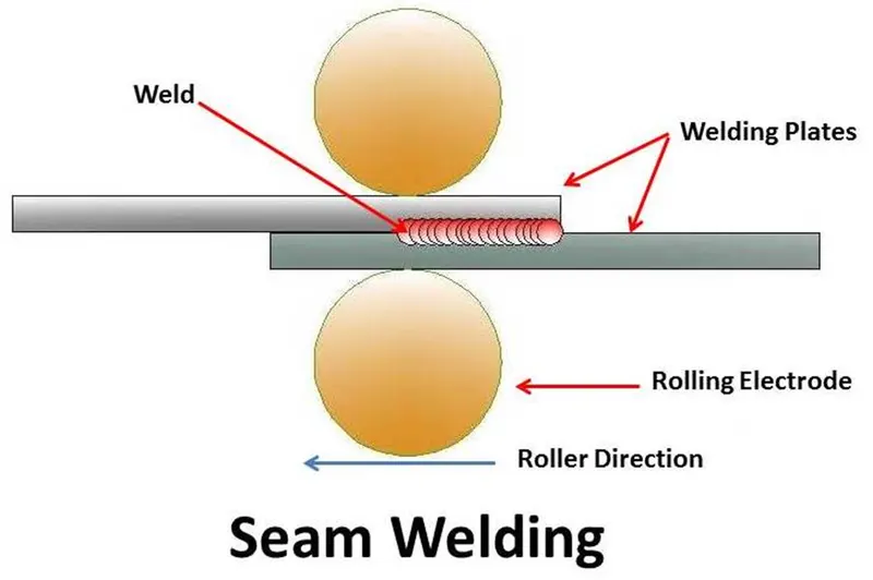
- Seam welding is a resistance welding process for joining metal sheets in continuously , often leak tight , seam joints by directly applying opposing forces with electrodes consisting of rotary wheels .
- The current & the heat generation are localized by the peripheral shapes of electrodes wheels.
Principle of seam welding
- Two electrodes made from copper & in the circular form is used. An impulse current is applied through one of the discs & pressure through the other on the materials that are being joined
- When the materials passes between electrodes they rotate. In this way , the electrode remains In contact with the material for a long time & forms a weld joint progressively unlike spot welding which forms an entire joint at once .
- Seam welding core principles are similar to that of the resistance spot welding . time , electricity & pressure are used to welds metals together . it is a type of electric resistance welding
 .
.
Advantages of resistance seam welding
- The welding is a quicker than the spot welding .
- It is a continuous welding technique suitable for gas and liquid tight containers
- Energy is utilized efficiently in this technique.
- This technique is ideal for making gas or liquid tight vessels .
- It doesn’t need the use of filler material.
Disadvantages of seam welding
- Higher current is required as compared to spot welding .
- For harder alloys , high strength welding forces are required .
- The electrode may need to be cleaned after one revolution
- The mechanized cleaning system is necessary for removal of contaminations
- It requires a greater amount of current
Applications
- Mostly use in manufacturing of containers , radiators and heat exchangers
- It is used in the assembly of fuel tanks in the automotive industry
- Especially used in case of seam welded tubes and pipes
- It is also used in the fabrication of heat exchangers
- This welding is used to make leakproof tanks , drums ,radiators , house hold utensils , automobile bodies etc .
Resistance Projection welding
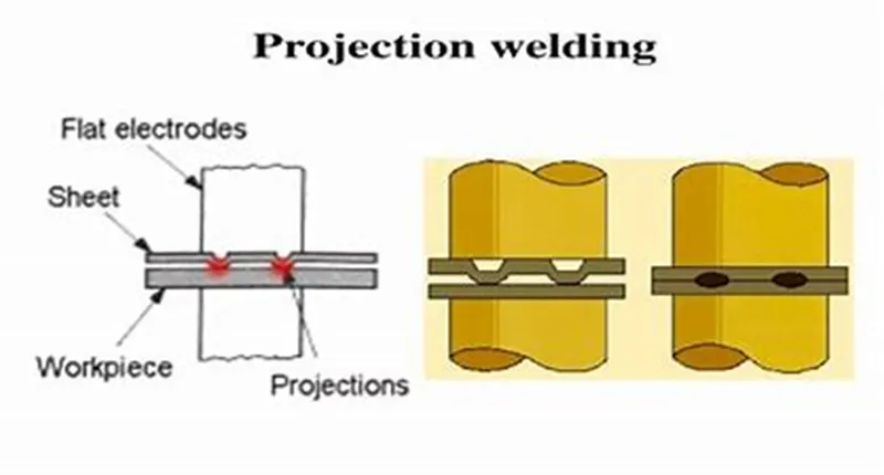
In the projection welding , as per the name , different projections are formed for effective welding . projection welding is one of the type of resistance welding and its working principle is quite the same as resistance welding . the only difference here is that projection or embossed joints are used for the welding purpose .
Projection welding is a resistance welding process for joining metal components or sheets with embossment by directly applying forces with electrodes specially design to fit the shapes of the workpieces .
The current & the heat generation are localized by the shape if the workpiece either with their natural shapes or with specially designed projection . and large deformation or collapse will occur in the projection part of the workpieces implying high .
Applications
Used for mechanical fixing of auto body structure (eg). Weld nuts
4)what is fusion welding& type of fusion welding with their applications in the automotive sector?
Definition
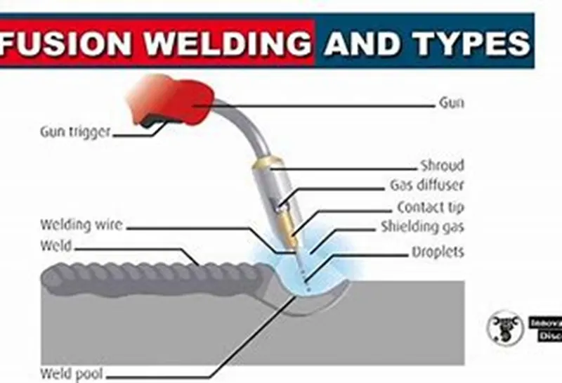
- The fusion welding process involved localized melting and solidification and is normally used when joining similar materials belonging to the same family .
- In fusion welding , the weld can be made by simply melting the edges of the two workpieces and allowing them to fuse together on cooling . this type of weld is referred to as an autogenous weldThe other method is to add extra material during the welding
- process through the melting of a filler wire or electrode during the welding process . in both cases , the welded area will have a microstructure and properties that are different from the parent metal
- The three predominant zones in a fusion , a heat – affected zone (HAZ), And the base metal.
- To maintain tolerance , distortion due to localized heating and cooling must be prevented or controlled by the use of jigs and fixture .
- Fusion welding is classified into three.
- Gas welding
- Arc welding
- Thermit welding
GAS WELDING
A type of chemical – based fusion welding , oxyfuel welding involves the use of a flame to heat and join surfaces , with oxygen as the fuel source , fire , of course , need oxygen , which is the basics on which oxyfuel welding works . the oxygen fuels the fire to create a hot flame in excess of 4,500 degrees Fahrenheit . oxyfuel welding typically uses a combination of oxygen and flammable gas to create a hot flame to join objects.
Oxy-acetylene uses a high-heat , high temperature flame that is produced by burning a fuel gas mixed with pure oxygen . the base material is melted with the filler rod using a flame from the combination of oxy-fuel gas through the tip of the welding torch.
The fuel gas and oxygen gas are stored in pressurized steel cylinders. Regulators in the cylinder reduce gas pressure .
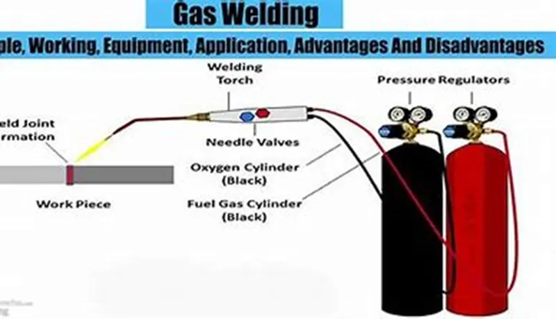
Gas flows through flexible hoses, with the welder controlling the flow via the torch . the filler rod is then melted with the base material . however , melting two pieces of material is also possible without the need for the filler rod .
It is used in automotive industries to weld parts of the frame and chassis.
ARC WELDING
the most popular type of fusion welding is arc welding . ARC welding lives up to is namesake by relying on an electric arc to join two or more objects .with electric arcs measuring up to 6000 degrees Fahrenheit , this fusion welding process is highly capable of melting even the toughest metals. Furthermore , arc welding can be performed underwater , making it an ideal solution for offshore welding projects .
MIG WELDING
MIG welding is a welding process in which an electric arc forms between a consumable wire electrode and the workpiece. This process uses inert gases or gas mixtures as the shielding gas. Argon and helium are typically used for the MIG welding of non-ferrous metals such as aluminium.
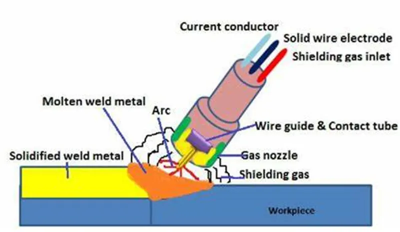
MIG welding allows for the fast production of high-quality welds and due to a lock of flux being used . there is no chance of slag being trapped in the weld metal. MIG welding is used in the fabrication of sheet metal and also can be used for deep groove welding .
SHIELD METAL ARC WELDING
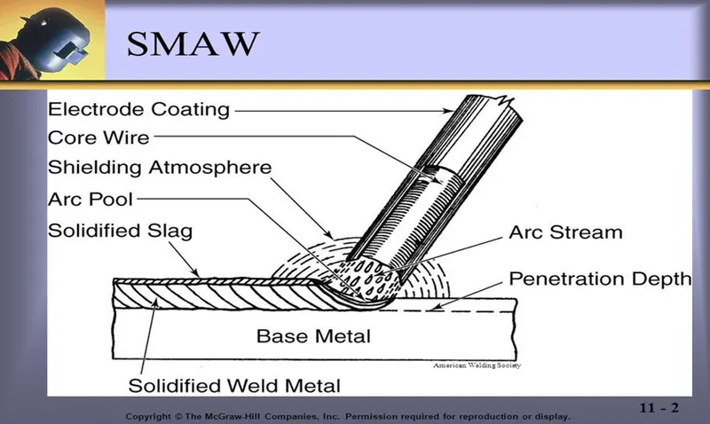
Shield metal arc welding , otherwise known as manual metal arc welding or flux shielded arc welding , is a process that uses a flux – coated electrode to form the weld . as electricity passes through the electrode , the flux forms a gas , which shields the electric arc in the space between the electrode and the metal being welded , preventing contamination from atmospheric gases in the weld . this process is fairly simple and doesn’t require much in the way of specialized equipment.
TIG WELDING
In the TIG welding process , the arc is formed between a pointed tungsten electrode and the workpiece in an inert atmosphere of argan and helium. The small intense arc provided by the pointed electrode is ideal for high quality and precision welding. Because the electrode is not consumed during welding , the TIG welder does not have to balance the heat input from the arc as the metal is deposited from the melting electrode. When filler metal is required , it must be added separately to the weld pool.
TIG welding is applied in all industrial sectors but is especially suitable for high-quality welding .
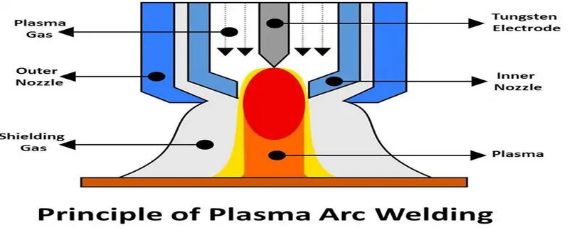
PLASMA ARC WELDING
This process uses an electric arc created between an electrode and the torch nozzle. The electric arc ionizes the gas in the chamber creating plasma. It is them forces through a fine boring copper nozzle that directs the arc to the workpiece , allowing the plasma arc to be separated from the shielding gas.
5.What is the 3-2-2 principle?
- The 3-2-1 method is work -holding principle where these pins are located on the 1st principle plane ,i.e. either xy, yz, zx. And two pins are located on the 2nd plane which is perpendicular to the 1st plane , and at last one pin on the plane which is mutually perpendicular to the 1st and 2nd The ultimate goal is to constrain the movement of the workpiece along three axes.
- Minimum from the above figure , we can see three locator blocks positioned at the primary locating surface. These three locators restrict the axial upward and downward movement along with it the two radial movements both clockwise and anticlockwise are also restricted . so, a total of four radial movements is restricted to the two mutually perpendicular axes.
- Round locating pins .these pin added in the location of the hole restricts the axial movements of two perpendicular axes. Thus , restricting four degrees of freedom.
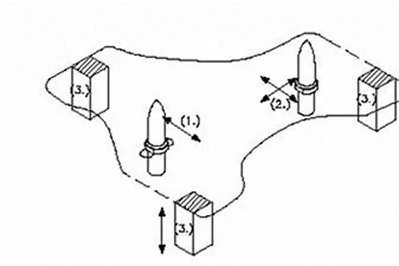
- Round locating pin is added to the slot in order to restrict the remaining radial movement in both clockwise and anticlockwise. This , therefore restricted the remaining two degrees of freedom.
- Thus the 3-2-1 principle is used to restrict the 12 degrees of freedom of a part.
6.Define body coordinate system?
- The body coordinate system is widely used in the automotive industries for drawing body parts , products , and process design.
- A coordinate system is a reference system consisting of a set of points, lines and surfaces used to define the position of points in space in either two or three dimensions .
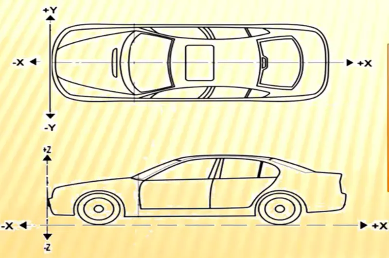
- To represent the position of BIW car parts, welding fixture and its unit assemblies with its individual parts in 2D drawings , their respective positions are shown with reference to (x=0,y=0,z=0)positions. In short, it shows in 2D XY , YZ or ZX coordinate position of BIW welding fixture parts or assemblies with reference to origin x=0,y=0,z=0.
- Let us consider a situation if an individual fixture designer starts designing a part or panel on their default axes system them it will be difficult to assembly or position the part with respect to each other. So in order to avoid this all the designer starts designing with respect to car axes system
- We consider a Cartesian graph
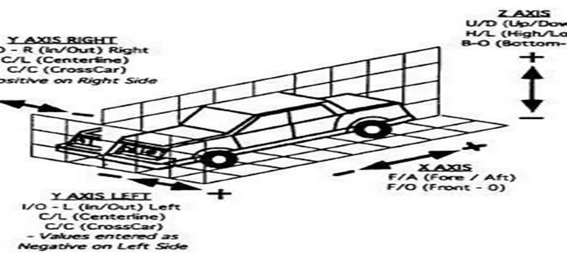
X - longitudinal direction [Front ‘o’ line – FOL]
Y – Transverse direction [ centre ‘o’ line – COL ]
Z – Vertical direction [ bottom ‘o’ line – BOL ]
- The origin of the body coordinate system OX is defined at the front centre of the car and it indicates the length of the car. The origin of the OZ [bottom O line ] is defined at the bottom of the car in the plane where the tire of the vehicle touches the ground and it indicates the height of the car. Finally , the origin of the OY coordinate lies in the centre of the car. Finally , the origin of the OY coordinate lies in the centre of the car it indicates the width.
7.Elaborate Body Plane System & its essential.
- Body planes are reference planes in an automotive car. These planes are used to define the GD&T of all car parts in an automotive domain.
- Body planes are three mutually perpendicular imaginary planes. These are generally considered to be present at the driver position or sometimes at the front end of the car
- The measurement from the body planes to the body parts called body line dimensions.
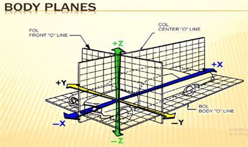
The need of the body planes are as below
- It defines the exact position of each part of the car with respect to a fixed origin.
- It ensures flawless design for assembly .
- It assists in the location of different parts in the vehicle .
- It creates a standard system.
- It is very helpful in quality checks.